


 Loading...
O P E R A T I N G M A N U A L
SQS-242™
Deposition Control Software
IPN 074-551-P1A

O P E R A T I N G M A N U A L
SQS-242
Deposition Control Software
IPN 074-551-P1A
www.inficon.com reachus@inficon.com
©2011 INFICON
Trademarks
The trademarks of the products mentioned in this manual are held by the companies that produce them.
LabVIEW™ is a trademark of National Instruments.
Z-Match® and SQS-242™ are trademarks of INFICON GmbH.
Access®, ActiveX®, Windows® and Microsoft® are registered trademarks of Microsoft Corporation.
All other brand and product names are trademarks or registered trademarks of their respective companies.
Disclaimer
The information contained in this manual is believed to be accurate and reliable. However, INFICON assumes no responsibility for its use and shall not be liable for any special, incidental, or consequential damages related to the use of this product.
Due to our continuing program of product improvements, specifications are subject to change without notice.
Copyright
©2011 All rights reserved.
Reproduction or adaptation of any part of this document without permission is unlawful.

Warranty
WARRANTY AND LIABILITY - LIMITATION: Seller warrants the products manufactured by it, or by an affiliated company and sold by it, and described on the reverse hereof, to be, for the period of warranty coverage specified below, free from defects of materials or workmanship under normal proper use and service. The period of warranty coverage is specified for the respective products in the respective Seller instruction manuals for those products but shall not be less than one (1) year from the date of shipment thereof by Seller. Seller's liability under this warranty is limited to such of the above products or parts thereof as are returned, transportation prepaid, to Seller's plant, not later than thirty (30) days after the expiration of the period of warranty coverage in respect thereof and are found by Seller's examination to have failed to function properly because of defective workmanship or materials and not because of improper installation or misuse and is limited to, at Seller's election, either (a) repairing and returning the product or part thereof, or (b) furnishing a replacement product or part thereof, transportation prepaid by Seller in either case. In the event Buyer discovers or learns that a product does not conform to warranty, Buyer shall immediately notify Seller in writing of such non-conformity, specifying in reasonable detail the nature of such non-conformity. If Seller is not provided with such written notification, Seller shall not be liable for any further damages which could have been avoided if Seller had been provided with immediate written notification.
THIS WARRANTY IS MADE AND ACCEPTED IN LIEU OF ALL OTHER WARRANTIES, EXPRESS OR IMPLIED, WHETHER OF MERCHANTABILITY OR OF FITNESS FOR A PARTICULAR PURPOSE OR OTHERWISE, AS BUYER'S EXCLUSIVE REMEDY FOR ANY DEFECTS IN THE PRODUCTS TO BE SOLD HEREUNDER. All other obligations and liabilities of Seller, whether in contract or tort (including negligence) or otherwise, are expressly EXCLUDED. In no event shall Seller be liable for any costs, expenses or damages, whether direct or indirect, special, incidental, consequential, or other, on any claim of any defective product, in excess of the price paid by Buyer for the product plus return transportation charges prepaid.
No warranty is made by Seller of any Seller product which has been installed, used or operated contrary to Seller's written instruction manual or which has been subjected to misuse, negligence or accident or has been repaired or altered by anyone other than Seller or which has been used in a manner or for a purpose for which the Seller product was not designed nor against any defects due to plans or instructions supplied to Seller by or for Buyer.
This manual is intended for private use by INFICON® Inc. and its customers. Contact INFICON before reproducing its contents.
NOTE: These instructions do not provide for every contingency that may arise in connection with the installation, operation or maintenance of this equipment. Should you require further assistance, please contact INFICON.
www.inficon.com reachus@inficon.com

IPN 074-551-P1A
SQS-242 Operating Manual
Table Of Contents
Trademarks
Disclaimer
Copyright
Chapter 1
Introduction
1.1 Introduction. . . . . . . . . . . . . . . . . . . . . . . . . . . . . . . . . . . . . . . . . . . . . . . . . . 1-1
1.2 SQM-242 Deposition Control Card. . . . . . . . . . . . . . . . . . . . . . . . . . . . . . . . 1-2
1.3 Digital I/O . . . . . . . . . . . . . . . . . . . . . . . . . . . . . . . . . . . . . . . . . . . . . . . . . . . 1-3
Chapter 2
Quick Start
2.1 Introduction. . . . . . . . . . . . . . . . . . . . . . . . . . . . . . . . . . . . . . . . . . . . . . . . . . 2-1 2.2 Single-Layer Process Setup . . . . . . . . . . . . . . . . . . . . . . . . . . . . . . . . . . . . . 2-2 2.2.1 Create a New Process . . . . . . . . . . . . . . . . . . . . . . . . . . . . . . . . . . . . . . . . . 2-2 2.2.2 Edit Layer Parameters . . . . . . . . . . . . . . . . . . . . . . . . . . . . . . . . . . . . . . . . . 2-3 2.2.3 Edit Rate Ramps . . . . . . . . . . . . . . . . . . . . . . . . . . . . . . . . . . . . . . . . . . . . . 2-4 2.2.4 Edit Deposition . . . . . . . . . . . . . . . . . . . . . . . . . . . . . . . . . . . . . . . . . . . . . . 2-5 2.2.5 Edit Pre/Post Conditioning . . . . . . . . . . . . . . . . . . . . . . . . . . . . . . . . . . . . . . 2-5 2.2.6 Edit Source/Sensor. . . . . . . . . . . . . . . . . . . . . . . . . . . . . . . . . . . . . . . . . . . . 2-6 2.2.7 Edit Errors. . . . . . . . . . . . . . . . . . . . . . . . . . . . . . . . . . . . . . . . . . . . . . . . . . . 2-6 2.2.8 Save Edits . . . . . . . . . . . . . . . . . . . . . . . . . . . . . . . . . . . . . . . . . . . . . . . . . . 2-7 2.3 Single Layer Process Simulation . . . . . . . . . . . . . . . . . . . . . . . . . . . . . . . . . 2-7 2.3.1 Setup Displays . . . . . . . . . . . . . . . . . . . . . . . . . . . . . . . . . . . . . . . . . . . . . . . 2-8 2.3.2 Start Process . . . . . . . . . . . . . . . . . . . . . . . . . . . . . . . . . . . . . . . . . . . . . . . . 2-8 2.3.3 Preconditioning Phases . . . . . . . . . . . . . . . . . . . . . . . . . . . . . . . . . . . . . . . . 2-9 2.3.4 Deposition Phase with one Rate Ramp . . . . . . . . . . . . . . . . . . . . . . . . . . . . 2-9 2.4 SoftKey Functions . . . . . . . . . . . . . . . . . . . . . . . . . . . . . . . . . . . . . . . . . . . 2-10 2.5 Multi-Layer CoDeposition Process . . . . . . . . . . . . . . . . . . . . . . . . . . . . . . . 2-11 2.6 Conclusion . . . . . . . . . . . . . . . . . . . . . . . . . . . . . . . . . . . . . . . . . . . . . . . . . 2-15
Chapter 3
SQS-242 Software
3.1 Introduction. . . . . . . . . . . . . . . . . . . . . . . . . . . . . . . . . . . . . . . . . . . . . . . . . . 3-1
3.2 Installation and Registration . . . . . . . . . . . . . . . . . . . . . . . . . . . . . . . . . . . . . 3-3
3.3 Operation . . . . . . . . . . . . . . . . . . . . . . . . . . . . . . . . . . . . . . . . . . . . . . . . . . . 3-3
1 - 1

SQS-242 Operating Manual
3.4 Menu . . . . . . . . . . . . . . . . . . . . . . . . . . . . . . . . . . . . . . . . . . . . . . . . . . . . . . 3-4
3.4.1 File: Process. . . . . . . . . . . . . . . . . . . . . . . . . . . . . . . . . . . . . . . . . . . . . . . . . 3-4
3.4.2 File: Open and Save Database . . . . . . . . . . . . . . . . . . . . . . . . . . . . . . . . . . 3-5
3.4.3 File: Data Logging . . . . . . . . . . . . . . . . . . . . . . . . . . . . . . . . . . . . . . . . . . . . 3-5
3.4.4 File: Print . . . . . . . . . . . . . . . . . . . . . . . . . . . . . . . . . . . . . . . . . . . . . . . . . . . 3-7
3.4.5 File: User Login . . . . . . . . . . . . . . . . . . . . . . . . . . . . . . . . . . . . . . . . . . . . . . 3-7
3.4.6 File: Exit . . . . . . . . . . . . . . . . . . . . . . . . . . . . . . . . . . . . . . . . . . . . . . . . . . . . 3-7
3.5 Edit Menu . . . . . . . . . . . . . . . . . . . . . . . . . . . . . . . . . . . . . . . . . . . . . . . . . . . 3-8
3.5.1 Edit: Process . . . . . . . . . . . . . . . . . . . . . . . . . . . . . . . . . . . . . . . . . . . . . . . . 3-8
3.5.1.1 Layer Tab . . . . . . . . . . . . . . . . . . . . . . . . . . . . . . . . . . . . . . . . . . . . . . . . . . 3-10
3.5.1.2 Rate Ramps Tab . . . . . . . . . . . . . . . . . . . . . . . . . . . . . . . . . . . . . . . . . . . . 3-12
3.5.1.3 Deposit Tab . . . . . . . . . . . . . . . . . . . . . . . . . . . . . . . . . . . . . . . . . . . . . . . . 3-13
3.5.1.4 Condition Tab . . . . . . . . . . . . . . . . . . . . . . . . . . . . . . . . . . . . . . . . . . . . . . . 3-14
3.5.1.5 Source/Sensor Tab . . . . . . . . . . . . . . . . . . . . . . . . . . . . . . . . . . . . . . . . . . 3-15
3.5.1.6 Errors Tab . . . . . . . . . . . . . . . . . . . . . . . . . . . . . . . . . . . . . . . . . . . . . . . . . 3-16
3.5.1.7 Analog Inputs . . . . . . . . . . . . . . . . . . . . . . . . . . . . . . . . . . . . . . . . . . . . . . . 3-17
3.5.2 Edit: Films. . . . . . . . . . . . . . . . . . . . . . . . . . . . . . . . . . . . . . . . . . . . . . . . . . 3-18
3.5.3 Edit: Materials. . . . . . . . . . . . . . . . . . . . . . . . . . . . . . . . . . . . . . . . . . . . . . . 3-19
3.5.4 Edit: System . . . . . . . . . . . . . . . . . . . . . . . . . . . . . . . . . . . . . . . . . . . . . . . . 3-20
3.5.4.1 Outputs Tab . . . . . . . . . . . . . . . . . . . . . . . . . . . . . . . . . . . . . . . . . . . . . . . . 3-21
3.5.4.2 Sensors Tab . . . . . . . . . . . . . . . . . . . . . . . . . . . . . . . . . . . . . . . . . . . . . . . . 3-22
3.5.4.3 Analog Tab . . . . . . . . . . . . . . . . . . . . . . . . . . . . . . . . . . . . . . . . . . . . . . . . . 3-23
3.5.4.4 Indexers Tab . . . . . . . . . . . . . . . . . . . . . . . . . . . . . . . . . . . . . . . . . . . . . . . 3-24
3.5.4.5 I/O Tab . . . . . . . . . . . . . . . . . . . . . . . . . . . . . . . . . . . . . . . . . . . . . . . . . . . . 3-24
3.5.4.6 Card Tab . . . . . . . . . . . . . . . . . . . . . . . . . . . . . . . . . . . . . . . . . . . . . . . . . . 3-28
3.5.4.7 Comm Tab . . . . . . . . . . . . . . . . . . . . . . . . . . . . . . . . . . . . . . . . . . . . . . . . . 3-29
3.5.5 Edit: Security . . . . . . . . . . . . . . . . . . . . . . . . . . . . . . . . . . . . . . . . . . . . . . . 3-30
3.5.5.1 Users Tab. . . . . . . . . . . . . . . . . . . . . . . . . . . . . . . . . . . . . . . . . . . . . . . . . . 3-30
3.5.5.2 Access Tab. . . . . . . . . . . . . . . . . . . . . . . . . . . . . . . . . . . . . . . . . . . . . . . . . 3-31
3.6 View Menu . . . . . . . . . . . . . . . . . . . . . . . . . . . . . . . . . . . . . . . . . . . . . . . . . 3-32
3.7 Software Specifications . . . . . . . . . . . . . . . . . . . . . . . . . . . . . . . . . . . . . . . 3-33
3.8 INI File Parameters . . . . . . . . . . . . . . . . . . . . . . . . . . . . . . . . . . . . . . . . . . 3-37
Chapter 4
Digital I/O
4.1 Introduction. . . . . . . . . . . . . . . . . . . . . . . . . . . . . . . . . . . . . . . . . . . . . . . . . . 4-1
4.2 PLC Installation . . . . . . . . . . . . . . . . . . . . . . . . . . . . . . . . . . . . . . . . . . . . . . 4-1
4.3 PLC Setup and Test . . . . . . . . . . . . . . . . . . . . . . . . . . . . . . . . . . . . . . . . . . . 4-4
4.4 5.3 PLC Programming . . . . . . . . . . . . . . . . . . . . . . . . . . . . . . . . . . . . . . . . . 4-4
1 - 2
IPN 074-551-P1A

IPN 074-551-P1A
SQS-242 Operating Manual
Chapter 5
Communications
5.1 Introduction. . . . . . . . . . . . . . . . . . . . . . . . . . . . . . . . . . . . . . . . . . . . . . . . . . 5-1 5.2 Serial Interface . . . . . . . . . . . . . . . . . . . . . . . . . . . . . . . . . . . . . . . . . . . . . . . 5-1 5.3 Ethernet Interface . . . . . . . . . . . . . . . . . . . . . . . . . . . . . . . . . . . . . . . . . . . . . 5-1 5.4 ActiveX (COM) Interface. . . . . . . . . . . . . . . . . . . . . . . . . . . . . . . . . . . . . . . . 5-1 5.5 SQS-242 Comm Program . . . . . . . . . . . . . . . . . . . . . . . . . . . . . . . . . . . . . . 5-2
5.5.1 Setup for RS-232 or Ethernet . . . . . . . . . . . . . . . . . . . . . . . . . . . . . . . . . . . . 5-2 5.5.2 Setup for Active X Control . . . . . . . . . . . . . . . . . . . . . . . . . . . . . . . . . . . . . . 5-2 5.5.3 Communicating with the SQS-242 Program. . . . . . . . . . . . . . . . . . . . . . . . . 5-2 5.6 Protocol . . . . . . . . . . . . . . . . . . . . . . . . . . . . . . . . . . . . . . . . . . . . . . . . . . . . 5-2 5.6.1 Query Command Format . . . . . . . . . . . . . . . . . . . . . . . . . . . . . . . . . . . . . . . 5-3 5.6.1.1 Example: Software Version Query . . . . . . . . . . . . . . . . . . . . . . . . . . . . . . . . 5-3 5.6.1.2 Example: Response to Software Version Query . . . . . . . . . . . . . . . . . . . . . 5-3 5.6.2 Update Command Format . . . . . . . . . . . . . . . . . . . . . . . . . . . . . . . . . . . . . . 5-3 5.6.2.1 Example: Set Process Update . . . . . . . . . . . . . . . . . . . . . . . . . . . . . . . . . . . 5-3 5.6.2.2 Example Response: Set Process Update Succeeded . . . . . . . . . . . . . . . . . 5-3 5.6.2.3 Example Response: Set Process Update Failed . . . . . . . . . . . . . . . . . . . . . 5-4 5.7 Checksum Calculation . . . . . . . . . . . . . . . . . . . . . . . . . . . . . . . . . . . . . . . . . 5-4 5.8 Command Summary. . . . . . . . . . . . . . . . . . . . . . . . . . . . . . . . . . . . . . . . . . . 5-5 5.8.1 Query Process . . . . . . . . . . . . . . . . . . . . . . . . . . . . . . . . . . . . . . . . . . . . . . . 5-5 5.8.2 Update Process . . . . . . . . . . . . . . . . . . . . . . . . . . . . . . . . . . . . . . . . . . . . . . 5-5 5.8.3 Query/Update Layer . . . . . . . . . . . . . . . . . . . . . . . . . . . . . . . . . . . . . . . . . . . 5-6 5.8.4 Query/Update Film . . . . . . . . . . . . . . . . . . . . . . . . . . . . . . . . . . . . . . . . . . . . 5-7 5.8.5 Query Utility . . . . . . . . . . . . . . . . . . . . . . . . . . . . . . . . . . . . . . . . . . . . . . . . . 5-7 5.8.6 Update Utility . . . . . . . . . . . . . . . . . . . . . . . . . . . . . . . . . . . . . . . . . . . . . . . . 5-8 5.8.7 Query Measurement. . . . . . . . . . . . . . . . . . . . . . . . . . . . . . . . . . . . . . . . . . . 5-8 5.8.8 Query Register . . . . . . . . . . . . . . . . . . . . . . . . . . . . . . . . . . . . . . . . . . . . . . . 5-8 5.8.9 Update Register . . . . . . . . . . . . . . . . . . . . . . . . . . . . . . . . . . . . . . . . . . . . . . 5-8
Chapter 6
Loop Tuning
1 - 3

SQS-242 Operating Manual
This page is intentionally blank.
IPN 074-551-P1A
1 - 4
SQS-242 Operating Manual
Chapter 1
Introduction
1.1 Introduction
The SQS-242 Deposition Control Software, see Figure 1-1, works with the INFICON SQM-242 card to provide a powerful, PC based thin film deposition controller that can:
Measure up to eight quartz crystal sensors simultaneously.
Control up to six deposition source supplies simultaneously (CoDeposition).
Provide PreConditioning, multiple rate ramps, and feed/idle phases.
Graph deposition rate, rate deviation, or power output.
Store process, film and material parameters in Microsoft Access® database
Provide flexible and reliable digital I/O using an inexpensive PLC (PLC not provided by INFICON).
Figure 1-1 SQS-242 Software
IPN 074-551-P1A
1 - 1

SQS-242 Operating Manual
The six Soft Keys provide easy access to the common operating functions. A single tabbed dialog box provides all of the settings required for a thin film process. Material parameters, sensor/source setup, pre/post conditioning, and error conditions are all visible on a single dialog box. Process settings, numeric data, and graphical displays are displayed during all phases of deposition.
The SQS-242 software stores process parameters in a Microsoft Access compatible database. The SQS-242 software can be controlled from another computer using the RS-232 or Ethernet command protocol.
1.2 SQM-242 Deposition Control Card
The SQM-242 is a PCI expansion card for use in computers running the Microsoft® Windows operating system. See Figure 1-2. Each card measures up to four quartz sensors via BNC inputs, and supplies the control signal for two evaporation sources via a ¼” stereo phone plug. Up to six SQM-242 cards can be installed in a computer. A single SAM-242 piggyback card with four analog inputs and two control outputs can also be installed.
Figure 1-2 SQM-242 Card
IPN 074-551-P1A
Consult the separate SQM-242 card Operating Manual for detailed information on installing and using the SQM-242 and the SAM-242 cards.
1 - 2

SQS-242 Operating Manual
1.3 Digital I/O
Digital I/O for the SQS-242 software can be provided through an inexpensive, external, programmable logic controller (PLC), see Figure 1-3. This allows the PLC, and the associated I/O wiring, to be placed in a convenient location in a wiring cabinet. A single, serial communications cable runs to the computer. The PLC provides electrical isolation, fail-safe operation, and extensive I/O processing capabilities through its ladder logic programming.
Figure 1-3 Programmable Logic Controller (PLC)
IPN 074-551-P1A
1 - 3

SQS-242 Operating Manual
This page is intentionally blank.
IPN 074-551-P1A
1 - 4

IPN 074-551-P1A
SQS-242 Operating Manual
Chapter 2
Quick Start
2.1 Introduction
This chapter will provide a general overview on how to setup the SQS-242 deposition control program.
1Power On the Computer.
2Start the SQS-242 software from: Start Menu >> Programs >> INFICON >> SQS-242 Codep.
3User Login Dialog Box
The SQS-242 displays a progress bar during program startup, then a User Login dialog box. Select a User Name from the drop down box, enter the Password, then click OK. See section 3.5.5 on page 3-30 for more information on users, passwords, access levels, and registration.
NOTE: The SQS-242 software has one pre-assigned user by default. The user name is Super, with no Password.
4Process Database
The SQS-242 normally starts with the last active process displayed. If that process is not found, a Database Open dialog is displayed.
5Main Display
As you operate the SQS-242, the six SoftKey labels along the left of the dialog box will change to display appropriate functions.
Along the top of the display is a menu of less commonly used functions. This menu is available only when the SQS-242 is stopped (i.e., not running a deposition process).
6Simulate Mode
Simulate mode allows you to familiarize yourself with SQS-242 operation and test process recipes. Simulate Mode will be used for the remainder of this chapter.
If the first SoftKey is labeled START SIMULATE then the Simulate mode is active. Otherwise, click the Edit menu selection along the top of the display, then click System. On the Card tab, click the Simulate button. Select the Close SoftKey to activate Simulate mode.
2 - 1

SQS-242 Operating Manual
2.2 Single-Layer Process Setup
We will build a simple single-layer process as an introduction.
2.2.1 Create a New Process
1Click Edit >> Process.
2The Process Edit dialog box will display the setup data for the active process. Click New.. See Figure 2-1.
Figure 2-1 Process Edit dialog box
3Type a new process name using your keyboard, or the on-screen keyboard. Click Enter to save the new process name. See Figure 2-2.
Figure 2-2 Keyboard
IPN 074-551-P1A
2 - 2

IPN 074-551-P1A
SQS-242 Operating Manual
2.2.2 Edit Layer Parameters
4 Click Layer to display the layer parameters. See Figure 2-3.
Figure 2-3 Layer tab
5A Film is basically a material, plus the settings that will control its deposition. Select Film >> Gold Sample.
6We will be simulating a quartz sensor input that is controlling the deposition rate of Output 1. Select Output >> Output 1.
7Select Input >> Sensor(s).
8Click SetPt, then adjust the rate setpoint to 10 Å/s.
9Adjust Final Thickness to 1.000 kÅ.
NOTE: Time and Thickness Endpoints won’t be used for this example.
10System Setup determines the physical inputs and outputs that are used and displayed on the dialog box. For now use the Default system setup.
11Manual Start causes this layer to wait for user input before beginning. An optional user prompt is possible.
12We won’t use any indexers for this example, so select None.
2 - 3
SQS-242 Operating Manual
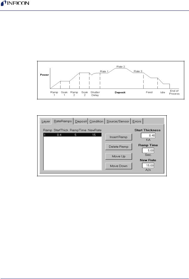
2.2.3 Edit Rate Ramps
A thin-film deposition process consists of one or more layers of material evaporated onto a substrate. Figure 2-4 illustrates a complete deposition cycle for a single layer. Refer to this diagram as we set the remaining parameters.It may be desirable to vary the deposition rate during a layer. For example, to deposit slowly at first, then more quickly once the initial material is deposited.
Figure 2-4 Complete Deposition Cycle for a Single Layer
13 Click Rate Ramps. See Figure 2-5.
Figure 2-5 Rate Ramps tab
14Click Insert Ramp.
15Set Start Thickness to 0.400 kÅ.
16Set Ramp Time to 5 seconds.
17Set New Rate to 15 Å/s.
NOTE: Settings on the Layer and Rate Ramp tabs must be set for each layer in a process. Settings on the remaining four tabs (Deposit, Condition, Source/Sensor, and Errors) correspond to the Film that was selected on the Layer tab. This allows a Film’s settings to be used in a number of layers, without the need to individually adjust each layer.
IPN 074-551-P1A
2 - 4

IPN 074-551-P1A
SQS-242 Operating Manual
2.2.4 Edit Deposition
18 Select the Deposit tab. See Figure 2-6.
Figure 2-6 Deposit tab
19Set gain (P Term) to 55.
20Set time constant (I Term) to 0.7.
21Set dead time (D Term) to 0.
22Be sure Shutter Delay Enabled is not selected.
23Set Rate Sampling to Continuous.
2.2.5Edit Pre/Post Conditioning
24Before deposition begins, the source material is often brought to a ready state by slowly raising the evaporation source power. Select the Condition tab and set each parameter to the values shown in Figure 2-7.
Figure 2-7 Condition tab
2 - 5
SQS-242 Operating Manual
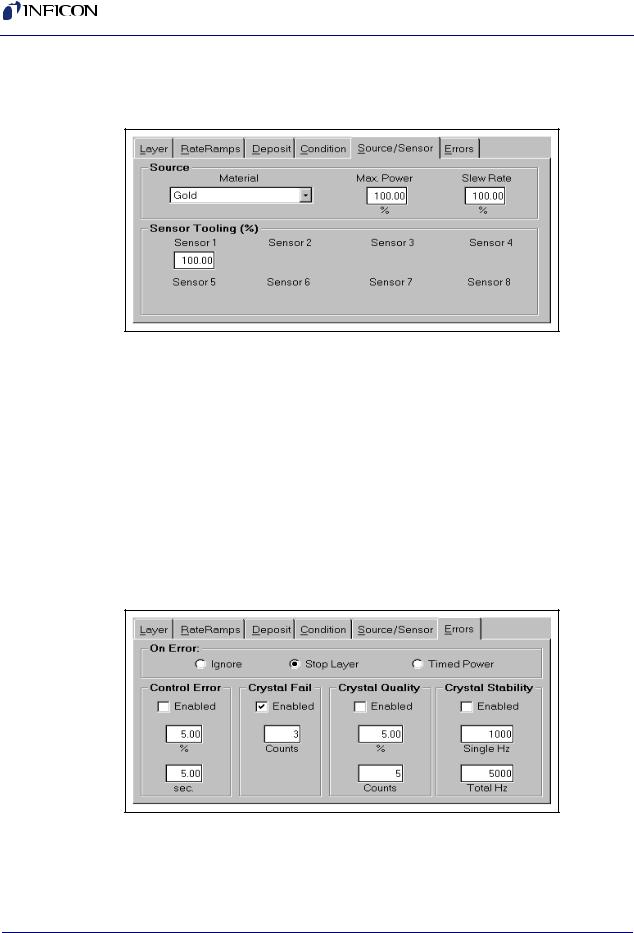
2.2.6 Edit Source/Sensor
25 Select the Source/Sensor tab. See Figure 2-8
Figure 2-8 Source/Sensor tab
26Select the proper material for this film, Gold.
27Set the maximum power and slew rate that should be used for the selected material.
28Sensor Tooling adjusts for differences in the substrate deposition and that measured by each sensor. Select 100% for now.
2.2.7Edit Errors
29Select the Errors tab, see Figure 2-9, to control the actions taken when a sensor or deposition control error occurs. You can elect to ignore errors (unlikely), stop deposition for this layer, or continue deposition at a fixed power level. Select Stop Layer for this example.
Figure 2-9 Errors tab
IPN 074-551-P1A
30Until a process is well established, it is best to enable only the Crystal Fail error checking. Uncheck the remaining error conditions.
2 - 6
SQS-242 Operating Manual
2.2.8 Save Edits
31Select the Close Form SoftKey to save this one-layer process. If you are prompted Do you want to change…. answer Yes to make this the current process.
32Your new single-layer process is now the active process in the main window. Notice the process, layer, and time information above the graph.
2.3Single Layer Process Simulation
If you have followed this chapter, you are ready to simulate a deposition process. First, take a look at the information provided on the main dialog box. See Figure 2-10.
Figure 2-10 Information on Main Dialog Box
Process |
Layer |
Phase |
Film(s) |
||||||||
Name |
Number |
Name |
|
|
|
||||||
|
|
|
|||||||||
Elapsed Time |
Elapsed Time |
Time Elapsed/Remaining |
|
|
|
||||||
Run Number |
|
|
|
Percent Complete |
|
|
|
||||
|
|
|
|
|
|
|
|
|
|
|
|
IPN 074-551-P1A
|
|
|
|
|
|
|
|
|
|
|
|
|
|
|
|
|
|
Operating |
Film |
Film |
||||||
Soft Keys |
Measurements |
Settings |
||||||
2 - 7

SQS-242 Operating Manual
2.3.1 Setup Displays
Click the View menu and make sure that these options are selected:
Film Settings
Film Readings
Automatic
Note that the settings “ribbon” along the right side of the dialog box displays the pre-conditioning parameters you entered in the previous section.
2.3.2 Start Process
Verify that the top SoftKey label displays START SIMULATE. If START PROCESS is displayed, follow the instructions at the end of section 2.1 to enable simulate mode. Press the START SIMULATE SoftKey to start the process.
The process will start with preconditioning (i.e., Ramp1, Soak1, Ramp2, Soak2) as shown in Figure 2-11. Once preconditioning is complete, the process will enter the Deposit phase.
Figure 2-11 Preconditioning
IPN 074-551-P1A
You may want to select ABORT SIMULATE, then START SIMULATE several times to familiarize yourself with the on-screen displays during preconditioning. You may also want to use the settings ribbon to adjust parameters while the process is running.
2 - 8
IPN 074-551-P1A
SQS-242 Operating Manual
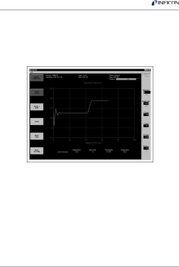
2.3.3 Preconditioning Phases
Because we selected Automatic in the View menu, the graph displays Output Power during preconditioning, then switches to Rate during the deposition phase.
As shown in Figure 2-12, the initial deposition rate was 10 Å/s until a thickness of
.400 kÅ. Then the deposition rate was ramped up to 15 Å/s, and held until the desired final thickness of 1.000 kÅ was achieved. At this point, this single-layer process is finished.
Figure 2-12 Deposition Rate
2.3.4 Deposition Phase with one Rate Ramp
You should adjust the PID parameters on the setting ribbon, then Start/Stop the process several times to become familiar with their effect on control loop response.
NOTE: In Simulate Mode, a deposition rate is not “measured” until the output power exceeds 50%.
2 - 9

SQS-242 Operating Manual
2.4 SoftKey Functions
As you have seen, the SoftKey functions remain constant during deposition. Spend a few minutes to become familiar with each of these SoftKey functions.
START PROCESS
Starts the first layer of a process when START is pushed. If AUTO MAN is shown on the third SoftKey (AUTO mode) the process starts PreConditioning. If MAN AUTO is shown on the third SoftKey (MANUAL mode) the process immediately starts in the Deposition phase.
ABORT PROCESS
Aborts the process. The process can only restart at the first layer.
START LAYER
Starts a stopped layer, or a layer that has been designated Manual Start in the process database. Starts the layer based on the state of the AUTO >> MAN SoftKey as described above.
STOP LAYER
Stops the current layer. Also changes the function of the first SoftKey to NEXT LAYER.
NEXT LAYER
Abandons the current layer and moves to the next layer in the process. If it is the last layer of a process, the same as pushing ABORT PROCESS.
AUTO MAN
When AUTO MAN is pushed, the source output is set to manual control. You may adjust the output using the settings ribbon. Because the PID loop is not running, you can manually set the output power to different levels and observe the associated deposition rate.
MAN AUTO
Returns the output to PID loop control. If the process is running (ABORT PROCESS and STOP LAYER shown on the first two SoftKeys) deposition continues. If the process is stopped, sets the output to zero and awaits a start command.
ZERO
Resets the thickness reading to zero.
NEXT FILM
Sequences the setting ribbon through each Film in a codeposition layer.
NEXT SETTING
When the settings ribbon is shown, sequences the setting knob action through each of the displayed parameters.
2 - 10
IPN 074-551-P1A
SQS-242 Operating Manual
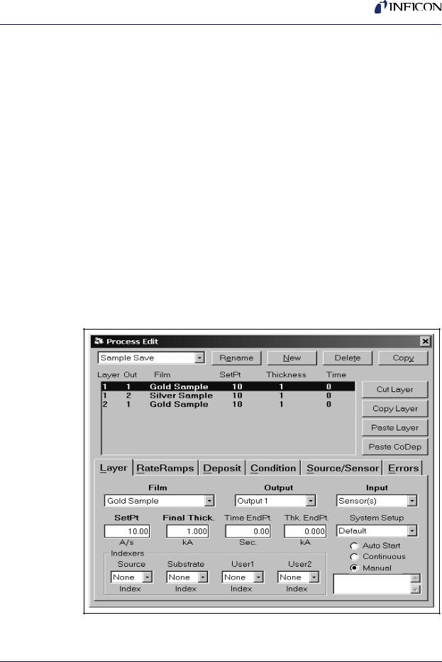
2.5 Multi-Layer CoDeposition Process
Our final example builds on the previous sections. If you have modified the setup of your process, return to section 2.2, Single-Layer Process Setup, on page 2-2 and adjust the process to those values. When your single-layer process matches section 2.2, complete these steps:
1Duplicate a Layer
Open the Edit Process dialog box. Click on Layer 1, click the Layer tab, then click Copy Layer. Now click Paste Layer. A duplicate Gold Sample film will be added as Layer 2. Click Paste Layer again to add a third Gold Sample layer.
2Select a CoDep Film
Select Layer 3 in the layers list. Select Films >> Silver Sample. Select Output >> Output 2. The layers list will update to show the new Silver Sample film assigned to Layer 3.
3Add a CoDep Layer
Select Layer 3 in the layers list, then click Cut Layer. Now select Layer 1. Click Paste CoDep. The Silver Sample film will be added below Gold Sample as a codeposition layer. Your setup should match Figure 2-13.
Figure 2-13 Added CoDep Layer
IPN 074-551-P1A
2 - 11

SQS-242 Operating Manual
We now have two layers in our process. Layer 1 has Gold being deposited from source Output 1 and Silver is being codeposited on Output 2. Layer 2 is Gold alone.
HINT: It’s easiest to copy a layer, then paste several temporary layers of that type as additional layers. Next, assign the films and outputs that you want to each of these additional layers. Now use Cut Layer on the temporary layers, and Paste CoDep to assign the film to the desired codeposition layers. Remember that each film in a codeposited layer must be assigned to a different source output! Review this example until you are comfortable with these concepts.
4Edit Layer 1 Rate & Thickness
Click Silver Sample in the list of layers. Set Initial Rate to 15 Å/s, Final Thickness to 1.500 kÅ. Click the Rate Ramps tab and set Start Thickness to 0.400 kÅ, Ramp Time to 15 seconds, and New Rate to 0 Å/s.
5Edit Layer 2 Rate & Thickness
Click the Layer tab, then click Layer 2 Gold Sample. Set Final Thickness to 0.5000 kÅ.
6Set Layers to Auto Start
At the end of deposition, you may choose to have the next layer wait for a Start Layer command, or to start automatically. Select each Layer in the layers list, then click Auto to set that layer to start automatically.
Verify that your process matches the one shown in Figure 2-14.
IPN 074-551-P1A
2 - 12
Loading...