


HELIX Series
Operations Manual
532509-5EN_A

Thank You!
Thank you for choosing Humminbird®, the #1 name in marine electronics. Humminbird has built its reputation by designing and manufacturing top quality, thoroughly reliable marine equipment. Your Humminbird is designed for trouble-free use in even the harshest marine environment. We encourage you to read this manual carefully in order to get the full benefit from all the features and applications of your Humminbird product.
Contact Humminbird Technical Support at humminbird.com or call 1-800-633-1468.
WARNING! This device should not be used as a navigational aid to prevent collision, grounding, boat damage, or personal injury. When the boat is moving, water depth may change too quickly to allow time for you to react. Always operate the boat at very slow speeds if you suspect shallow water or submerged objects.
WARNING! The electronic chart in your Humminbird unit is an aid to navigation designed to facilitate the use of authorized government charts, not to replace them. Only official government charts and notices to mariners contain all of the current information needed for the safety of navigation, and the captain is responsible for their prudent use.
WARNING! Humminbird is not responsible for the loss of data files (waypoints, routes, tracks, groups, recordings, etc.) that may occur due to direct or indirect damage to the unit’s hardware or software. It is important to back up your control head’s data files periodically. Data files should also be saved to your computer before restoring the control head defaults or updating the software. See the following sections of your Humminbird manual: Manage Screen Snapshots and Recordings and Manage your Navigation Data: Import/Export
Navigation Data.
WARNING! Disassembly and repair of this electronic unit should only be performed by authorized service personnel. Any modification of the serial number or attempt to repair the original equipment or accessories by unauthorized individuals will void the warranty.
WARNING! Do NOT leave the control head microSD or SD card slot cover open. The slot cover should always be closed to prevent water damage to the unit.
WARNING! Do not travel at high speed with the unit cover installed on the control head. Remove the unit cover before traveling at speeds above 20 mph.
WARNING! The user shall maintain 20 cm separation from the RF device to ensure compliance with RF exposure.
NOTE: Some features discussed in this manual require a separate purchase, and some features are only available on international models. Every effort has been made to clearly identify those features. Please read the manual carefully in order to understand the full capabilities of your model.
NOTE: The illustrations in this manual may not look the same as your product, but your unit will function in a similar way.
NOTE: To purchase accessories for your control head, visit our Web site at humminbird.com or contact Humminbird Technical Support at 1-800-633-1468.
NOTE: The procedures and features described in this manual are subject to change without notice. This manual was written in English and may have been translated to another language. Humminbird is not responsible for incorrect translations or discrepancies between documents.
NOTE: Product specifications and features are subject to change without notice.
NOTE: Humminbird verifies maximum stated depth in saltwater conditions, however actual depth performance may vary due to transducer installation, water type, thermal layers, bottom composition, and slope.
ROHS STATEMENT: Product designed and intended as a fixed installation or part of a system in a vessel may be considered beyond the scope of Directive 2002/95/EC of the European Parliament and of the Council of 27 January 2003 on the restriction of the use of certain hazardous substances in electrical and electronic equipment.
ATTENTION INTERNATIONAL CUSTOMERS: Products sold in the U.S. are not intended for use in the international market. Humminbird international units provide international features and are designed to meet country and regional regulations. Languages, maps, time zones, units of measurement, and warranty are examples of features that are customized for Humminbird international units purchased through our authorized international distributors.
To obtain a list of authorized international distributors, please visit our Web site at humminbird.com or contact Humminbird Technical Support at (334) 687-6613.
2

360 Imaging®, AUTOCHART®, AUTOCHART® LIVE, ChartSelect®, CoastMaster™, Contour XD™, Down Imaging®, DualBeam PLUS™, Fish ID+™, FishSmart™, HELIX®, Humminbird®, HumminbirdPC™, ICE HELIX® CHIRP Series, i-Pilot® Link™, LakeMaster®, MEGA Down Imaging™, MEGA Down Imaging+™, MEGA Imaging™, MEGA Side Imaging™, MEGA Side Imaging+™, Real Time Sonar™, RTS™, RTS Window™, Side Imaging®, SI™, Structure ID™, SwitchFire®, UniMap™, WhiteLine™, X-Press™ Menu, are trademarked by or registered trademarks of Johnson Outdoors Marine Electronics, Inc.
Adobe, Acrobat, Adobe PDF, and Reader are either registered trademarks or trademarks of Adobe Systems Incorporated in the United States and/or other countries.
Baekmuk Batang, Baekmuk Dotum, Baekmuk Gulim, and Baekmuk Headline are registered trademarks owned by Kim Jeong-Hwan.
The Bluetooth® word mark and logos are registered trademarks owned by the Bluetooth SIG, Inc. and any use of such marks by Johnson Outdoors, Inc. is under license. Other trademarks and trade names are those of their respective owners.
microSD and SD are trademarks or registered trademarks of SD-3C, LLC in the United States, other countries or both.
Navionics® Gold, HotMaps™, and HotMaps™ Premium, Navionics® Classic Charts, Navionics+™, and Platinum™ Cartography are trademarked by or registered trademarks of Navionics S.p.A.
 NMEA 2000® is a registered trademark of the National Marine Electronics Association.
© 2020 Johnson Outdoors Marine Electronics, Inc. All rights reserved.
3

Table of Contents
Warnings |
2 |
Introduction |
7 |
Using Humminbird Manuals on your Mobile Device or PC |
9 |
Getting Started |
10 |
HELIX Control Head |
19 |
Update Software |
25 |
Menu System Overview |
26 |
Open an X-Press Menu. . . . . . . . . . . . . . . . . . . . . . . . . . . . . . . . . . . 26 Open the Main Menu. . . . . . . . . . . . . . . . . . 26 Select a Menu . . . . . . . . . . . . . . . . . . . . . . 27 Change a Menu Setting. . . . . . . . . . . . . . . . . . 27 Tips for Using the Menu System. . . . . . . . . . . . . . 28 Change the User Mode (Angler or Custom). . . . . . . . . . . . . . . . . 29 Close the Menu System. . . . . . . . . . . . . . . . . . 29
Views |
30 |
Display a View. . . . . . . . . . . . . . . . . . . . . . . . . . . . . . . . . . . . . . . . . . . 30 Show your Favorite Views. . . . . . . . . . . . . . . . . 31 Save a View to the VIEW SHORTCUT Key. . . . . . . . . . 31 Display Digital Readouts. . . . . . . . . . . . . . . . . 32 Combo Views. . . . . . . . . . . . . . . . . . . . . . 36
Set up Sonar |
|
|
|
37 |
Display a Sonar View On-Screen |
|
50 |
||
Understand the Sonar Views . |
. . . . . . . . . . . . . . |
52 |
||
Customize the Sonar View . . |
. . . . . . . . . . . . . . |
53 |
||
Adjust Sonar Display Settings. |
. . . . . . . . . . . . . |
. 58 |
||
Adjust Settings While you Fish |
. . . . . . . . . . . . . |
. |
62 |
|
Compare Sonar Beams (Split Sonar View). . |
. . . . . . . |
67 |
||
Review Sonar History. . . . . . . . . . . . . . . . . . |
. 68 |
|||
Zoom In/Zoom Out. . |
. . . . . . . . . . . . . . . . . |
. 69 |
||
Navigation in Sonar Views.. . . . . . . . . . . . . . . . |
73 |
|||
Display a Down Imaging View On-Screen |
76 |
Understand the Down Imaging View . . . . . . . . . . . |
78 |
Customize the Down Imaging View.. . . . . . . . . . . . |
79 |
Adjust Settings While you Fish. . . . . . . . . . . . . . |
82 |
Review Down Imaging History and Zoom In/Out. . . . . . . 87 Navigation in Down Imaging Views. . . . . . . . . . . . . 89
Display a Side Imaging View On-Screen |
91 |
Understand the Side Imaging View.. . . . . . . . . . . . 93 Customize the Side Imaging View.. . . . . . . . . . . . 95 Adjust Settings While you Fish. . . . . . . . . . . . . . 98 Review Side Imaging History and Zoom In/Out . . . . . . . 105 Navigation in Side Imaging Views. . . . . . . . . . . . . 107
Ice Fishing Overview |
|
|
109 |
Understand the Flasher View . . . . . . . . . . . .. . |
. 110 |
||
Adjust Settings While you Fish. . . . . |
. . . . . . . . |
111 |
|
Move the Depth Cursor . . |
. . . . . . . . . . . . . . . |
115 |
|
Zoom In/Out in Flasher View. . . . . . . |
. . . . . . . |
116 |
|
Using Sonar Zoom View in Ice Fishing Mode. . . . . . . . . . . . . . |
. 118 |
||
Charge Glow-in-the-Dark Lures . . |
. . . . . . . . . . . |
120 |
|
Manage Screen Snapshots and Recordings |
121 |
||
Chart Overview |
|
|
129 |
Display a Chart View On-Screen . . . . . . . . . . . . . 130 Select a Map Source. . . . . . . . . . . . . . . . . . 132 Customize the Bird’s Eye View. . . . . . . . . . . . . . 138 Customize the Chart Instrument View. . . . . . . . . . . 139 Customize the Chart View. . . . . . . . . . . . . . . . 140 Display Chart Overlays. . . . . . . . . . . . . . . . . . 144 Display Humminbird LakeMaster
Contour Lines and Depth Ranges. . . . . . . . . . . . 146 Display Humminbird CoastMaster
Contour Lines and Depth Ranges. . . . . . . . . . . . 148 Change the Chart Orientation and Motion Mode. . . . . . 150
Navigation Overview |
152 |
Navigation Alarms Overview. . . . . . . . . . . . . . . |
154 |
Man Overboard (MOB) Navigation. . . . . . . . . . . . |
. 155 |
Waypoints |
157 |
Routes |
166 |
Tracks |
171 |
Search |
174 |
4

Table of Contents
Manage your Navigation Data |
176 |
Manage Waypoints. . . . . . . . . . . . . . . . . . . 179 Manage Routes. . . . . . . . . . . . . . . . . . . . . 183 Manage Tracks . . . . . . . . . . . . . . . . . . . . 190 Manage Groups. . . . . . . . . . . . . . . . . . . . . 192 Search and Organize . . . . . . . . . . . . . . . . . . 196 Import/Export Navigation Data. . . . . . . . . . . . . . 198 Delete All Navigation Data and Reset. . . . . . . . . . . 198
AutoChart Live Overview |
199 |
Plan your Map . . . . . . . . . . . . . . . . . . . . . |
199 |
Prepare the Control Head for Mapping. . . . . . . . . . |
200 |
Record your Custom Map . . . . . . . . . . . . . . . . |
203 |
Stop Recording. . . . . . . . . . . . . . . . . . . . . 204 |
|
Correct Data.. . . . . . . . . . . . . . . . . . . . . |
204 |
Using AutoChart Live in Ice Fishing Mode. . . . . . . . . |
205 |
Open the AutoChart Live Menu. . . . . . . . . . . . . |
206 |
Display the AutoChart Live Map. . . . . . . . . . . . . |
. 206 |
Customize the AutoChart Live Map Display Settings. . . . 208 |
|
Customize the Bottom Hardness Display Settings. . . . . 213 |
|
Customize the Vegetation Display Settings. . . . . . . . |
217 |
Set Up a NMEA 2000 Network |
221 |
Understand the NMEA 2000 Instrument View. . . . . . . |
225 |
Manage your Control Head |
226 |
Maintenance |
232 |
Troubleshooting |
233 |
Specifications |
235 |
Statements and Acknowledgements |
328 |
Contact Humminbird |
330 |
5

6

Introduction
The instructions in this manual describe the HELIX control head operations. Review the following table to understand the features that apply to your control head.
Model |
Sonar |
Down |
Side |
CHIRP |
Ethernet |
GPS |
(2D) |
Imaging |
Imaging |
(optional) |
(Charts and Navigation) |
||
|
|
|
|
|
|
|
HELIX GPS G2 |
|
|
|
|
|
|
|
|
|
|
|
|
|
HELIX SONAR G2 |
|
|
|
|
|
External GPS, trackplotting |
|
|
|
|
|
(separate purchase required) |
|
|
|
|
|
|
|
|
|
|
|
|
|
|
|
HELIX DI G2 |
|
|
|
|
|
External GPS, trackplotting |
|
|
|
|
|
(separate purchase required) |
|
|
|
|
|
|
|
|
|
|
|
|
|
|
|
HELIX CHIRP DI G2 |
|
|
|
|
|
External GPS, trackplotting |
|
|
|
|
|
(separate purchase required) |
|
|
|
|
|
|
|
|
|
|
|
|
|
|
|
HELIX CHIRP GPS G2/G2N |
|
|
|
|
G2N |
|
|
|
|
|
models only |
|
|
|
|
|
|
|
|
|
|
|
|
|
|
|
|
HELIX CHIRP DI GPS G2/G2N |
|
|
|
|
G2N |
|
|
|
|
|
models only |
|
|
|
|
|
|
|
|
|
|
|
|
|
|
|
|
HELIX CHIRP SI GPS G2/G2N |
|
|
|
|
G2N |
|
|
|
|
|
models only |
|
|
|
|
|
|
|
|
|
|
|
|
|
|
|
|
HELIX CHIRP MEGA SI GPS G2N |
|
MEGA |
MEGA |
|
|
|
|
|
|
|
|
|
|
HELIX CHIRP MEGA DI GPS G2N |
|
MEGA |
|
|
|
|
|
|
|
|
|
|
|
ICE HELIX CHIRP G2 |
|
|
|
|
|
External GPS, trackplotting |
|
|
|
|
|
(separate purchase required) |
|
|
|
|
|
|
|
|
|
|
|
|
|
|
|
ICE HELIX CHIRP GPS G2/G2N |
|
|
|
|
G2N models |
|
|
|
|
|
(in Open Water Mode only) |
|
|
|
|
|
|
|
|
|
|
|
|
|
|
|
|
ICE HELIX CHIRP GPS G3/G3N |
|
|
|
|
G3N models |
|
|
|
|
|
(in Open Water Mode only) |
|
|
|
|
|
|
|
|
|
|
|
|
|
|
|
|
HELIX CHIRP GPS G3/G3N |
|
|
|
|
G3N |
|
|
|
|
|
models only |
|
|
|
|
|
|
|
|
|
|
|
|
|
|
|
|
HELIX CHIRP MEGA DI GPS G3/G3N |
|
MEGA |
|
|
G3N |
|
|
|
|
models only |
|
||
|
|
|
|
|
|
|
|
|
|
|
|
|
|
HELIX CHIRP MEGA SI GPS G3/G3N |
|
MEGA |
MEGA |
|
G3N |
|
|
|
models only |
|
|||
|
|
|
|
|
|
|
|
|
|
|
|
|
|
HELIX CHIRP MEGA DI+ GPS G3N |
|
MEGA+ |
|
|
|
|
|
|
|
|
|
|
|
HELIX CHIRP MEGA SI+ GPS G3N |
|
MEGA+ |
MEGA+ |
|
|
|
|
|
|
|
|
|
|
HELIX CHIRP GPS G4N |
|
|
|
|
|
|
|
|
|
|
|
|
|
HELIX CHIRP MEGA DI GPS G4N |
|
MEGA |
|
|
|
|
|
|
|
|
|
|
|
HELIX CHIRP MEGA DI+ GPS G4N |
|
MEGA+ |
|
|
|
|
|
|
|
|
|
|
|
HELIX CHIRP MEGA SI+ GPS G4N |
|
MEGA+ |
MEGA+ |
|
|
|
|
|
|
|
|
|
|
7 |
Introduction |
Operations Summary Guide: For an overview of functions, see the Operations Summary Guide (or Quick Start Guide) included with your product.
Accessories: Some of the features shown in this manual require a separate purchase. Radar, AIS, Compass/Heading Sensor, Ethernet, i-Pilot Link, etc. require a separate purchase. For the list of accessories that are compatible with your control head, visit our Web site at humminbird.com. To install each accessory, use the installation guide provided with it, or download the guide from our Web site.
Ethernet Models: Visit our Web site at humminbird.com to purchase Ethernet cables and switches, and to download the Ethernet Networking Installation and Operations Manual.
Register and Update: Visit our Web site at humminbird.com to register your product(s), update control head and accessory software, and purchase additional equipment. Also, see Update Software in this manual for more information.
Introduction |
8 |
Using Humminbird Manuals on your Mobile Device or PC
The Humminbird manuals for your control head and accessories can be downloaded to your mobile device or PC. If you prefer to use a hard copy for reference, this manual may be printed.
Download the Manual to your Mobile Device
1.Download the free Adobe Acrobat Reader app to your mobile device.
2.Go to our Web site at humminbird.com, and click Support > Manuals.
3.Select the PDF for your control head model or accessory, and save it to your device.
4.Open the Adobe Acrobat Reader app.
5.Open the Humminbird manual.
Download the Manual to your PC
1.Download the free Adobe Acrobat Reader software from http://get.adobe.com/reader/, and install it on your PC.
2.Go to our Web site at humminbird.com, and click Support > Manuals.
3.Select the PDF for your control head model or accessory, and save it to your device.
4.Open Adobe Acrobat Reader.
5.Open the Humminbird manual.
Jump to a Section: Click a section name in the Bookmarks panel. Bookmarks can be expanded and collapsed by clicking on the plus (+) or minus (-) icons.
Search for Words or Phrases: Press and hold the Ctrl F keys on your PC keyboard. Type the word(s) into the text box. Print: If you prefer to use a hard copy for reference, this manual may be printed.
Using the Manual
search for bookmarks key words
panel
(Ctrl + F)
9 |
Introduction |

Getting Started
The procedures in this section describe how to get started with your control head. Some of the settings in this section are a one-time set up, and other settings (such as checking the GPS reception) you will use each time you hit the water.
Power On
Follow the instructions below to power on your Humminbird control head.
1.Press the POWER key.
2.When the Title screen is displayed, press the MENU key.
Title Screen
Press the MENU key
3. Select Normal. Press the RIGHT Cursor key.
Getting Started |
10 |
Normal mode is required for on-the-water operation. If a functioning transducer is connected Normal to the control head, Normal will be selected automatically, and your control head can be used
on the water.
To learn how to use your control head, select Simulator. You can save menu settings and Simulator navigation data in Simulator mode (see Chart Overview and Navigation Overview for more
information).
To view system information for software version, GPS reception, and accessory connections,
System Status select System Status. See Check Accessory Connections and Check GPS Reception for more information.
NOTE: If you wait too long to select a start-up option, the system will start the mode that is already highlighted. If your control head goes into Demonstration mode, please note that menu settings cannot be saved in this mode (see Manage your Control Head).
Starting Normal Mode for on-the-water Operations
Press the
RIGHT Cursor key
11 |
Getting Started |

Quick Setup
If this is the first time the unit has been powered on (after installation or after restoring defaults), the Quick Setup menu will display.
Set up the Control Head |
Quick Setup Menu |
|
1.Use the Cursor Control key to change the settings.
2.Close: Press the EXIT key.
|
The available languages are determined by your Humminbird model. |
|||
Language |
|
|
WARNING! Do NOT enable Asian Mode if you do not require Asian languages. Before you select |
|
|
|
|||
|
|
|
||
|
|
|
Asian Mode, contact Technical Support for important information. |
|
|
|
|
|
|
|
Set the maximum depth of the body of water. When Max Depth is set to Auto, the control head |
|||
|
will acquire bottom readings as needed (within the capabilities of the unit). When Max Depth |
|||
Max Depth |
is set to match your water maximum depth, the control head will not attempt to acquire sonar |
|||
data below that depth, so more detail will be shown on the display. |
||||
|
Side Imaging units default to the Side Imaging range setting if the SI Range is set deeper than |
|||
|
the Max Depth. See the Side Imaging section for more information. |
|||
|
|
|
|
|
|
Water Type affects the accuracy of deep water depth readings and configures the control head |
|||
Water Type |
for operation in fresh or salt water. |
|||
In salt water, you can also choose the shallow or deep setting. If the depth is more than 330 ft |
||||
|
||||
|
(100 m), select Salt (deep). |
|||
|
|
|
|
|
|
The control head will automatically select the transducer that was included with your control |
|||
Connected |
head. If your model is compatible with an accessory transducer, and it is connected to the |
|||
Transducer |
control head, select the transducer in the system so the beams are activated and the related |
|||
|
views are added to the control head. |
|||
|
|
|
|
|
NOTE: To change the Max Depth, Water Type, and the Connected Transducer after the initial Setup, see Set up Sonar.
Getting Started |
12 |
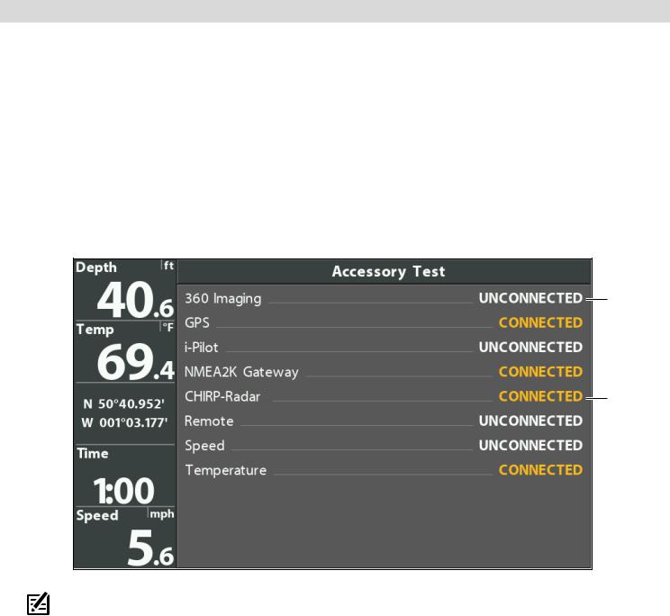
Check Accessory Connections
If you’ve connected other separate-purchase equipment to the control head, such as AIS, Compass/Heading Sensor, and more, use these instructions to confirm the equipment is detected and communicating with the control head. You can also check Ethernet accessory connections from this view.
1.Press and hold the VIEW key.
2.Select System > Accessory Test.
Confirm all accessories are listed as Connected. If you have a temp/speed wheel, the wheel must move for it to be detected.
Unconnected: If an accessory is listed as Unconnected, check the cable and power connections to confirm they are secure and powered on. Review the installation guide that was included with your accessory to confirm it is installed correctly.
To change the NMEA 2000 network, see Set Up a NMEA 2000 Network.
Confirming Accessories are Detected (HELIX 9 CHIRP SI GPS G2N)
unconnected (not detected by the control head)
connected
NOTE: The menus for installed accessories are typically included in the Accessory tab in the Main Menu. See your accessory guide for details. For the latest list of accessories that are compatible with your control head, visit our Web site at humminbird.com.
13 |
Getting Started |
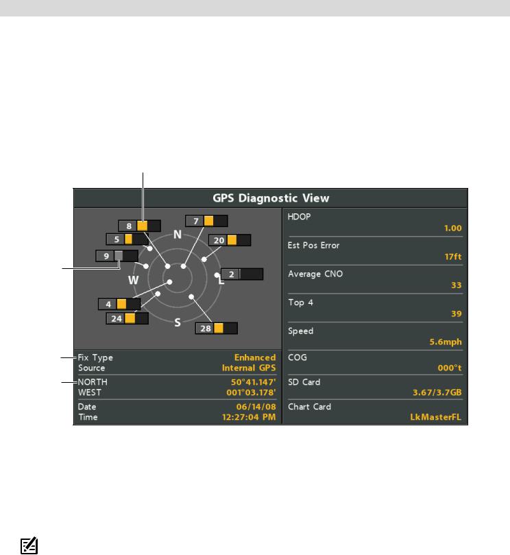
Check GPS Reception
If your control head includes internal GPS, or if it is connected to an External GPS receiver, use the instructions in this section to confirm the control head has GPS reception.
1.Press and hold the VIEW key.
2.Select System > GPS Diagnostic View.
Confirm GPS Fix Type is shown as Enhanced or 3D.
Confirm that the latitude/longitude position readout is displayed.
Reviewing GPS Reception
active satellite signal strength (yellow)
monitored satellite signal strength (gray)
fix type shown as enhanced
latitude/longitude position
GPS Reception: The sky chart displays the satellite number and signal strength bar.
GPS Fix Type: reported as No Fix, 2D Fix, 3D Fix, or Enhanced. An Enhanced Fix has been augmented using information from WAAS, EGNOS, or MSAS.
HDOP (the Horizontal Dilution of Precision): a GPS system parameter which depends on the current satellite configuration. HDOP is used to calculate the Estimated Position Error.
NOTE: To manually change your GPS source, change the output frequency, or turn on GLONASS, see Manage your Control Head.
Getting Started |
14 |

Set Alarms
When an alarm is turned on, an alert will sound or display on the control head to indicate the threshold has been exceeded.
Turn on Alarms and Adjust Settings
1.Main Menu: Press the MENU key twice.
OR
To open the Main Menu from a System View, press the MENU key once.
2.Select the Alarms tab.
3.Select an alarm menu. Press the RIGHT or LEFT Cursor keys to adjust the threshold.
Depth Alarm |
The alarm will be triggered when the depth becomes equal to or less than the menu setting. |
|
Transducer required. |
||
|
||
|
|
|
Fish ID Alarm |
The alarm will be triggered when a fish is detected based on the menu setting. See Adjust |
|
Sonar Display Settings for more information. |
||
|
||
|
|
|
|
The alarm will be triggered when the input battery voltage is equal to or less than the menu |
|
Low Battery Alarm |
setting. The battery must be connected to the control head. Set the alarm to a level that will |
|
alert you when the battery is low but at a level that is high enough to start the engine and run |
||
|
||
|
essential electronics. See your control head installation guide for more information. |
|
|
|
|
|
The alarm will be triggered when the water temperature detected by the control head is |
|
Temp. Alarm |
equal to the temp alarm setting. Input from the built-in transducer temperature sensor or a |
|
|
temperature accessory is required. |
|
|
|
|
Off Course Alarm |
Sets how far the boat can move off course during navigation before an alarm will be triggered. |
|
GPS required. See Navigation Overview for more information. |
||
|
||
|
|
|
Arrival Alarm |
Sets how close the boat must be to the destination waypoint before the alarm will be triggered. |
|
GPS required. See Navigation Overview for more information. |
||
|
||
|
|
|
Drift Alarm |
Sets how far the boat can move from its anchored position outside the drift alarm perimeter |
|
before an alarm will be triggered. GPS required. See Navigation Overview for more information. |
||
|
||
|
|
NOTE: The available alarms are determined by the connected equipment, so your control head may provide more or less options than the information shown here. If there are accessories installed, review the accessory guide for alarm information.
4. Close: Press the EXIT key twice.
Exit an Alarm
If an alarm is triggered during control head operation, you can close it or silence it using these instructions.
 1. Press any key on the control head.
15 |
Getting Started |

Change Units of Measurement
Use the instructions in this section to change the units of measurement format.
HELIX G3/G3N and older
1.Main Menu: Press the MENU key twice.
2.Select the Setup tab.
3.Select Units - Depth, Units - Distance, etc., and adjust each unit setting as needed.
4.Close: Press the EXIT key.
NOTE: You can also change the time and date format, language, and installation offsets from this menu. See
Manage your Control Head for more information.
HELIX G4N
1.Main Menu: Press the MENU key twice.
2.Select the Data Sources tab.
3.Select Units and press the RIGHT Cursor key to open the
Units menu.
4.Select each unit as needed and use the RIGHT or LEFT Cursor keys to adjust the setting.
5.Close: Press the EXIT key.
Reset the Triplog
The Triplog includes the timer for elapsed time, distance traveled since last reset, and average speed. Use the following instructions to reset the triplog. To display the Triplog as a digital readout, see Views: Display Digital Readouts.
HELIX G3/G3N and older
1.Main Menu: Press the MENU key twice.
2.Select the Setup tab.
3.Select Triplog Reset.
4.Press the RIGHT Cursor key.
5.Follow the on-screen prompts.
HELIX G4N
1.Main Menu: Press the MENU key twice.
2.Select the Data Sources tab.
3.Select Reset Trip Log.
4.Press the RIGHT Cursor key.
5.Follow the on-screen prompts.
Turn on/off Sounds
Use the instructions in this section to choose the category of sounds you want to hear from your control head.
1.Main Menu: Press the MENU key twice.
2.Select the Setup tab.
3.Select Sound Control.
4.Select All Sounds or Alarms Only.
To receive a sound alert from an alarm, Sound Control must be set to All Sounds or Alarms Only.
Change the Alarm Tone: Select the Alarms tab > Alarm Tone.
Change the User Mode
The User Mode determines how many menu options are displayed in the menu system. Select Angler to see fewer menu options that are used more often. Select Custom to see all the menu options available in the menu system.
Instructions in this manual marked with Main Menu (Custom User Mode) indicate that the menu system User Mode must be set to Custom for the selected menu to be shown. If you do not see the menu in the system, change the User Mode to Custom. See
Menu System Overview for details.
1.Main Menu: Press the MENU key twice.
2.Select the Setup tab.
3.Select User Mode.
4.Select Angler or Custom.
Getting Started |
16 |

Set up Sonar
If you’ve installed an accessory transducer, or to refine your sonar settings or turn on/off Ice Fishing Mode, see Set up Sonar for details.
Set up Chart Preferences
If you’ve installed a microSD or SD map card, see Chart Overview to set up the map source.
Pair a Phone with the Control Head (HELIX G2N/G3N/G4N Series only)
If you have a HELIX G2N, G3N or G4N Series control head, you can pair a phone with it using Bluetooth wireless technology.
Pair a Phone with the Control Head
HELIX G2N and G3N |
HELIX G4N |
1.Main Menu: On the HELIX control head, press the MENU key twice.
2.Open the Phone Bluetooth Menu: Select the Accessories tab.
Select Phone Bluetooth. Press the RIGHT Cursor key.
3.Select Bluetooth.
4.Select On.
5.Select Connect New Phone. Press the RIGHT Cursor key.
It will take a moment for this option to appear in the menu.
6.Follow the on-screen prompts to start the pairing process.
If the phone is not found, select Search for Phone. Press the RIGHT Cursor key.
7.When the phone name displays in the menu, select it. Press the RIGHT Cursor key.
1.Main Menu: On the HELIX control head, press the MENU key twice.
2.Open the Phone Bluetooth Menu: Select the Accessories tab.
Select Phone Bluetooth. Press the RIGHT Cursor key.
3.Select Connect Phone. Press the RIGHT Cursor key.
4.Follow the on-screen prompts to start the pairing process through your phone.
5.When prompted, tap Pair on your phone.
6.In your phone Settings menu, turn on Show Notifications.
8.Check your phone. When prompted, tap Pair on your phone.
9.In your phone Settings menu, turn on Show Notifications.
Change the Phone Bluetooth Alert Format
Use the following instructions to select an alert format on the control head or turn off alerts.
1.On the HELIX control head, open the Phone Bluetooth menu.
 NOTE: In your phone Settings menu, confirm that Bluetooth is turned on and Show Notifications is turned on.
2.Select Text Message Alerts or Phone Call Alerts.
Press the RIGHT or LEFT Cursor keys to select an alert format. To turn off notifications, select off.
3.Select Sounds. Select On or Off.
17 |
Getting Started |

Review Phone Bluetooth Notifications
Use the Views X-Press Menu to review notifications. 1. Press and hold the VIEW key.
Reviewing Phone Bluetooth Information
|
|
|
|
|
|
|
|
|
|
|
|
|
|
phone |
|
battery |
|
|
|
text |
call |
|
phone |
carrier |
|||||
notifications |
notifications |
power percentage |
signal strength |
||||||
Adjust the Backlight
1.Press the POWER key.
2.Select Light.
3.Adjust the Backlight setting from Dim to 10 (brightest).
Start Standby Mode
To conserve power while the control head is not in-use, start Standby mode.
1.Press the POWER key.
2.Select Standby.
3.Press the RIGHT Cursor key.
4.Turn off: Press the POWER key.
Power Off
Use the following instructions to power off your control head. Your control head should always be turned off using the POWER key.
If you are currently navigating, you should save the current track before powering off.
Save the Current Track
1.Chart X-Press Menu: With a Chart View displayed on-screen, press the MENU key once.
2.Select Save Current Track.
3.Press the RIGHT Cursor key.
Power Off
1. Press and hold the POWER key.
Getting Started |
18 |

HELIX Control Head
HELIX 5 SONAR G2, HELIX 5 DI G2, ICE HELIX 5 CHIRP G2
VIEW
MENU
EXIT
ICE HELIX 5 CHIRP GPS G2
|
|
|
|
|
|
|
|
|
|
|
|
19 |
|
|
The Control Head |
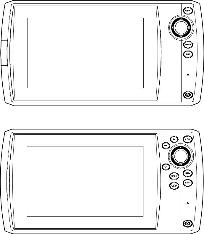
HELIX 7 SONAR G2, HELIX 7 CHIRP DI G2
HELIX 7 G2/G2N and G3/G3N Series Models (with Internal GPS), ICE HELIX 7 CHIRP GPS G3/G3N
|
|
|
|
|
|
|
|
|
|
|
|
|
|
|
The Control Head |
20 |
|
|
|
HELIX 8, 9, 10, 12 G2N/G3N/G4N Series
HELIX 15 G4N
21 |
The Control Head |

Control Head Keys
The available keys are determined by your control head model. Your control head might not include all the keys shown in this section.
ZOOM In (+)/ZOOM Out (–) keys
Press the ZOOM keys to change the scale of the view. For a closer view, press the ZOOM IN (+) key. For a wider view, press the ZOOM OUT (-) key. You can also magnify the cursor selection. You can also press these keys to adjust the sensitivity in sonar views (Sonar, DI, SI).
VIEW key
Press and hold the VIEW key to open the Views X-Press menu, or press the VIEW key repeatedly until the view you want to use is displayed on the screen. Press the EXIT key to display the previous view. See Views for details.
CHECK/INFO key
In the Chart View, press the CHECK/INFO key to see information about the cursor position or about objects located near the cursor position. If the cursor is not active, the Chart Info submenu will open. See
Navigation Overview for details.
In Sonar Views, press this key once to switch frequencies (if available). See each sonar section (Sonar, DI, SI) for details.
Cursor Control key
(LEFT, RIGHT, UP, or DOWN Cursor keys)
Press the arrows on the Cursor Control key to move through the menu system, select menus, and change or activate menu settings. See Menu System Overview for
 details.
Also, press any arrow on the Cursor Control key to move the cursor on the view.
To move the cursor diagonally, press in between the arrows.
MARK key
Press the MARK key to save a waypoint at the boat position. If the cursor is active, press the MARK key twice to save a waypoint at the cursor position. See
Navigation Overview for details.
If a microSD or SD card is installed, press and hold this key to save a Screen Snapshot. See Manage Screen Snapshots and Recordings for details.
MENU key
To open the X-Press Menu for the on-screen view and operation mode, press the MENU key once. To open the Main Menu, press the MENU key twice. See Menu System Overview for details.
GO TO/Man Overboard (MOB) key
With an active cursor, press the GOTO key twice to create a waypoint and start navigation towards that waypoint. If the cursor is not active, press the GOTO key, and choose from the saved navigation data.
To start Man Overboard navigation, press and hold the GOTO key. See Navigation Overview and Man Overboard (MOB) Navigation for details.
EXIT key
Press the EXIT key to close a menu, close a dialog box, turn off an alarm, or exit Cursor mode.
Also, press the EXIT key to scroll through the View Rotation in reverse order. See Views for details.
VIEW SHORTCUT key
Press and hold a VIEW SHORTCUT key to save a shortcut to the on-screen view. You can save one view on each VIEW SHORTCUT key. See Views for details.
POWER key
Press the POWER key to power on the control head. To power off, press and hold the POWER key.
During operation, press the POWER key. The backlight can be adjusted from this menu. You can also turn on/off Sonar, change the view background color, and start Standby mode.
The Control Head |
22 |

SD Card or microSD Card Slot
Your control head may be compatible with an SD or microSD card (separate purchase required). Use it to update software, add detailed charts to your control head, import/export navigation data, and save sonar recordings and screen snapshots. Use the instructions in this section to install the card.
Add Maps: see Chart Overview.
Import/Export Navigation data: See Manage your Navigation Data.
Sonar Recordings and Screen Snapshots: See Manage Screen Snapshots and Recordings.
Software Updates: For details, see Update Software.
CAUTION! Before the control head software is updated or restored to system defaults, export your navigation data (see Update Software).
Insert an SD Card
Follow these steps if your control head is compatible with SD cards.
1.Remove the SD card slot cover.
2.Position the SD card so that the label faces to the left.
3.Insert the card into the slot until it clicks into place.
4.Replace the slot cover so it is secure.
5.Remove: Press the card into the slot and then release it. The card will eject. Pull the card carefully from the slot.
NOTE: Do not leave the SD card slot cover open. The slot cover should always be closed to prevent water damage to the unit.
Insert a microSD Card
Follow these steps if your control head is compatible with microSD cards.
Insert the SD card with the label facing to the left
1.Remove the microSD card slot cover.
2.Side Card Slot: Position the microSD card so that the label faces the front of the control head and the card notches face down.
Front Card Slot: Position the microSD card so that the label faces to the left and the card notches face up.
3.Insert the card into the slot until it clicks into place.
4.Replace the slot cover so it is secure.
5.To Remove: Press the card into the slot and then release it. The card will eject. Pull the card carefully from the slot.
 NOTE: Do not leave the card slot cover open. The slot cover should always be closed to prevent water damage to the unit.
23 |
The Control Head |

Removing the microSD Card Slot Cover (HELIX 5, HELIX 7)
Installing a microSD Card (magnified view) (HELIX 5, HELIX 7)
notch facing down
The Control Head |
24 |

Update Software
Register your product at humminbird.com so that you will receive the latest Humminbird news and software updates for your Humminbird model. You can also download HumminbirdPC, which allows you to manage your waypoints, routes, and tracks on your personal computer.
If your control head model does not include a microSD or SD card slot, you can use HumminbirdPC to update the control head software. Visit humminbird.com for details.
NOTE: It is important to back up your control head’s data files (waypoints, routes, tracks, groups, recordings, etc.) periodically. Data files should also be saved to your PC before restoring the unit’s defaults or updating the software. See Manage your Navigation Data: Import/Export Navigation Data and Manage Screen Snapshots and Recordings for more information. Also, contact Humminbird Technical Support with any questions.
Required Equipment: Personal computer with Internet access, and a formatted microSD or SD card. See HELIX Control Head for compatibility details.
Register your Humminbird Products
Register your Humminbird product and sign up to receive the latest Humminbird news, including software updates and new product announcements.
1.Go to our Web site at humminbird.com and click Support > Register your Product.
2.Follow the on-screen instructions to register your product.
Update the Control Head Software
Use the following instructions to download software updates from humminbird.com.
1.Install a formatted microSD or SD card into the slot on your PC.
2.Download: Click Support > Software Updates. The available software updates are listed as Downloads under each product.
•Under Downloads, click the file name. Confirm the file name is for your control head model.
•Read the instructions in the dialog box and select Download.
•Follow the on-screen prompts to save the software file to the microSD or SD card.
3.Install the microSD or SD card with the updated software file into the control head card slot.
4.Power On: The control head will recognize the new software and run through a series of prompts to confirm the software installation.
25 |
Update Software |

Menu System Overview
The menu system provides menu options that are determined by the operations mode, on-screen view, and connected accessories.
Open an X-Press Menu
The X-Press Menu displays menus that are related to the on-screen view and the operations mode (such as navigation). In this illustration, the Sonar X-Press Menu is displayed because the Sonar View is displayed on the screen.
Open the X-Press Menu
1.Press the VIEW key repeatedly until the view you want is displayed on-screen.
2.Press the MENU key once.
Opening the Sonar X-Press Menu
 x1
x1
Open the Main Menu
The main menu is divided into tabbed categories (Alarms, Sonar, Navigation, |
Opening the Main Menu |
Chart, Humminbird Chart, Setup, Views, and Accessories). The available tabs |
|
|
|
and menus are determined by your model and the connected accessories. |
|
Open the Main Menu
1. Press the MENU key twice.
|
|
|
|
|
|
|
|
Menu System Overview |
26 |
|
|

Select a Menu
Use the Cursor Control key to select a menu in the Main Menu or X-Press Menu.
Select a Tab (Main Menu)
1. Press the RIGHT or LEFT Cursor keys.
Select a Menu
1. Press the DOWN or UP Cursor keys.
Select a Tab
Select a Menu
Change a Menu Setting
Use the Cursor Control key to change menu settings or start an action. When you change a menu setting, the view will update immediately.
Adjust a Menu Setting
1. Press the RIGHT or LEFT Cursor keys.
Change a Menu Setting
|
|
|
|
|
|
27 |
Menu System Overview |
|

Start an Action/Open a Submenu
1.If a menu has a right arrow on it, press the RIGHT Cursor key to start the action or open the submenu.
Tips for Using the Menu System
You can move through the menu system quickly using the following tips.
Jump to the Bottom of the Tab
Jump to the Top of the Tab
Start an Action or Open a Submenu
See More Menus
Menu System Overview |
28 |
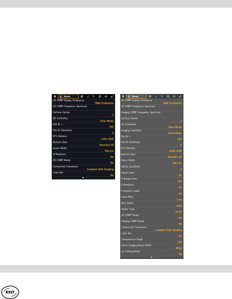
Change the User Mode (Angler or Custom)
The User Mode determines how many menus are shown in the menu system. Select Angler to see fewer menus that are used more often. Select Custom to see all the menus available in the menu system.
Main Menu (Custom User Mode): Instructions in this manual marked with Main Menu (Custom User Mode) indicate that the menu system User Mode must be set to Custom for the selected menu to be shown. If you do not see the menu in the system, change the User Mode to Custom.
Change the User Mode
1.Main Menu: Press the MENU key twice.
2.Select the Setup tab.
3.Select User Mode.
4.Select Angler or Custom.
Main Menu: Sonar Tab (User Mode set to Angler)
Main Menu: Sonar Tab (User Mode set to Custom)
Close the Menu System
Use the EXIT key to go back through the menu system or close the menu system.
Back: Press the EXIT key to close the current menu and go back one level in the menu system. Close: Press the EXIT key repeatedly until the menu system is closed.
29 |
Menu System Overview |
Views
The HELIX control head has many options to display data on-screen, and the data can be displayed in a variety of ways. There are also several ways to quickly display a view on-screen. To see the list of views available on your control head, see Show your Favorite Views.
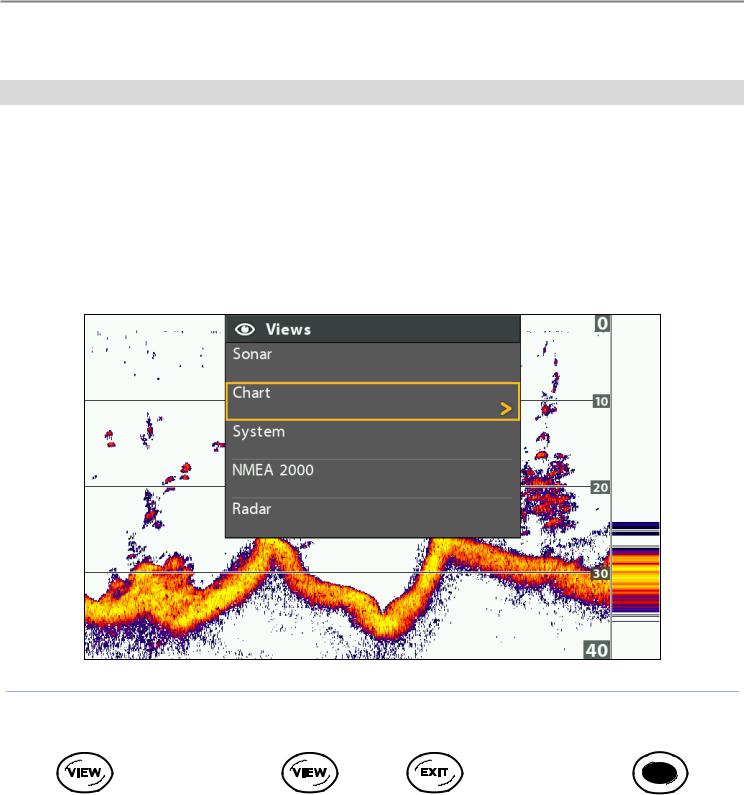
Display a View
The available views are determined by the control head model, installed transducer, and connected accessories.
Display a View from the Views X-Press Menu
1.Press and hold the VIEW key.
2.Select a view category. Press the RIGHT Cursor key.
3.Select a view. Press the RIGHT Cursor key.
Selecting a View to Display on the Screen
OR |
OR |
Press and Hold to Open |
Forward: Press to go |
Back: Press to go to |
Press to Display |
the Views X-Press Menu |
to the Next View |
the Previous View |
a Saved View |
|
|
|
|
Views |
30 |
 Loading...