


190cx
PiranhaMAX™ 150,160,170,180,190c
PiranhaMAX™ 150,160,170,180,190c
Installation and Operations Manual
Installation and Operations Manual
531678-1_B

Thank You!
Thank you for choosing Humminbird®, America's #1 name in fishfinders.
Humminbird® has built its reputation by designing and manufacturing
top-quality, thoroughly reliable marine equipment. Your Humminbird® is
designed for trouble-free use in even the harshest marine environment.In the
unlikely event that your Humminbird® does require repairs, we offer an
exclusive ServicePolicy-free of charge during the first year after purchase,and
available at a reasonable rate after the one-year period. For complete details,
see the Warranty section of this manual. We encourage you to read this
installation and operations manual carefully in order to get full benefit from all
the features and applications of your Humminbird® product.
Contact our Customer Resource Center at 1-800-633-1468 or visit our website
at www.humminbird.com. The PiranhaMAX™ comes in five models:
• PiranhaMAX™150 - Single Beam, 160 V x 128 H Monochrome Display
• PiranhaMAX™160 - Dual Beam, 160 V x 128 H Monochrome Display
• PiranhaMAX™170 - Dual Beam, 240 V x 160 H Monochrome Display
• PiranhaMAX™180 - Tri Beam, 240 V x 160 H Monochrome Display
• PiranhaMAX™190c - Single Beam, 320 V x 240 H Transmissive ColorDisplay.
WARNING! This device should not be used as a navigational aid to prevent collision,
grounding, boat damage, or personal injury. When the boat is moving,water depth may
change too quickly to allow time for you to react. Always operate the boat at very slow
speeds if you suspect shallow water or submerged objects.
WARNING! Do not touch an active transducer during operation, as this may cause
physical discomfort and mayresult in personalinjuryin the formof tissuedamage.Handle
the transducer only when the power to the control head is off.
WARNING! Disassembly and repair of this electronic unit should only be performed by
authorized service personnel. Any modification of the serial number or attempt to repair
the original equipment or accessories by unauthorized individuals will void the warranty.
Handling and/or opening this unit may result in exposure to lead, in the form of solder.
WARNING! This product contains lead, a chemical known to the state of California to
cause cancer, birth defects and other reproductive harm.
ENVIRONMENTAL COMPLIANCE STATEMENT:It is the intention of Humminbird®
to be a responsible corporate citizen, operating in compliance with known and
applicable environmental regulations, and a good neighbor in the communities where
we make or sell our products.
i

WEEE DIRECTIVE: EU Directive 2002/96/EC “Waste of Electrical and Electronic
Equipment Directive (WEEE)”impactsmost distributors, sellers,and manufacturers of
consumer electronics in the European Union. The WEEE Directive requires the
producer of consumer electronics to take responsibility for the management of waste
from their products to achieve environmentally responsible disposal during the
product life cycle.
WEEE compliance may not be required in your location for electrical & electronic
equipment (EEE), nor may it be required for EEE designed and intended as fixed or
temporary installation in transportation vehicles such as automobiles, aircraft, and
boats.In some European Union member states, these vehiclesare consideredoutside
of the scope of the Directive, and EEE for those applications can be considered
excluded from the WEEE Directive requirement.
This symbol (WEEE wheelie bin) on product indicates the product must not
be disposed of with other household refuse. It must be disposed of and
collected for recyclingand recoveryof wasteEEE. Humminbird® will mark all
EEE productsin accordancewiththe WEEE Directive. It is our goal to comply
in the collection, treatment, recovery, and environmentally sound disposal of those
products; however, these requirementdo vary within European Union member states.
For more information about where you should dispose of your waste equipment for
recycling and recovery and/or your European Union member state requirements,
please contact your dealer or distributor from which your product was purchased.
ROHS STATEMENT: Product designed and intended as a fixed installation or part of
a system in a vessel may be consideredbeyond the scope of Directive 2002/95/EC of
the European Parliament and of the Council of 27 January 2003 on the restriction of
the use of certain hazardous substances in electrical and electronic equipment.
CALIFORNIA PROPOSITION 65 STATEMENT: Lead in cable jackets and boots is
restricted to 300 parts per million or less as determined by ICP-AES test methods.
NOTE: Some features discussed in this manual require a separate purchase, and
some features are only available on international or certain models. Every effort has
beenmade to clearlyidentify those features.Please read the manual carefully in order
to understand the full capabilities of your model.
NOTE: Illustrations in this manual may not look the same as your product, but your
unit will function in the same way.
Humminbird®, Piranha® , PiranhaMAX™, Fish ID+™, Structure ID®, WhiteLine™, are
trademarked by or registered trademarks of Humminbird® .
© 2008 Humminbird®, Eufaula AL, USA. All rights reserved.
ii

Table of Contents
Installation Overview 1
Control Head Installation 2
Determine Where to Mount .............................................................................. 2
Connect the Power Cable to the Boat .............................................................. 2
Assembling the Control Head Base ............................................................ 4
Routing the Control Head Cables Under the Deck .................................... 5
Attaching the Control Head to the Base .................................................... 6
Attaching the Cables to the Control Head.................................................. 7
Transom Installation Overview 8
Transom Transducer Installation 9
Locating the Transducer Mounting Position .............................................. 9
Preparing the Mounting Location ............................................................ 11
Assembling the Transducer and Initial Mounting .................................... 12
Routing the Cable...................................................................................... 16
Test and Finish the Installation ................................................................ 18
Inside the Hull Transducer Installation 20
Determine the Transducer Mounting Location ........................................ 21
Trial Installation ........................................................................................ 22
Route the Cable ........................................................................................ 23
Permanently Mount the Transducer ........................................................ 23
Trolling Motor Transducer Installation 24
Powering ON and OFF 25
What You See On the Display 26
PiranhaMAX™ Sonar Technology 28
Single Beam Sonar .................................................................................... 29
Dual Beam Sonar ...................................................................................... 29
Tri Beam Sonar .......................................................................................... 29
iii

Table of Contents
The Menu System 30
Light (Setting Not Saved in Memory) ........................................................ 30
Sensitivity (Setting Saved in Memory) ...................................................... 30
Depth Range (Setting Not Saved in Memory) .......................................... 31
Zoom (Setting Not Saved in Memory)........................................................ 31
Chart Speed (Setting Saved in Memory) .................................................. 32
Fish Alarm (Setting Saved in Memory) ...................................................... 32
Depth Alarm (Setting Not Saved in Memory)............................................ 32
Filter (Setting Saved in Memory) .............................................................. 33
SetUp Menu (Setting Not Saved in Memory)............................................ 33
Contrast (Setting Saved in Memory) .................................................... 33
Fish ID+™ (Setting Saved in Memory) ................................................ 34
Bottom View (Setting Saved in Memory).............................................. 34
Battery Alarm (Setting Saved in Memory)............................................ 36
Language (Setting Saved in Memory, International Only).................... 36
Units (Setting Saved in Memory, International Only) .......................... 36
Maintenance 37
Troubleshooting 38
International Purchases 41
1-Year Limited Warranty 42
Humminbird® Service Policy 43
Returning Your Unit for Service 44
Specifications 45
Contact Humminbird® 46
NOTE: Entries in thisTable of Contentswhichlist (International Only)are only available
on products sold outside of the U.S. by our authorized International Distributors. It is
important to note that products sold in the U.S. are not intended for resale in the
international market. Toobtain a listof authorized InternationalDistributors,pleasevisit
our website at www.humminbird.com or contact our Customer Resource Center at
1-800-633-1468 to locate the distributor nearest you.
iv


Installation Overview
Installation Overview
Before you start installation, we encourage you to read these instructions
carefully in order to get the full benefit from your PiranhaMAX™.
There are three basic installation tasks that you must perform for the
PiranhaMAX™:
• Installing the control head
• Installing the transducer
• Testing the complete installation and locking the transducer position.
1
Control Head Installation
Control Head Installation
Determine Where to Mount
Begin the installation by determining where to mount the control head.
Consider the following to determine the best location:
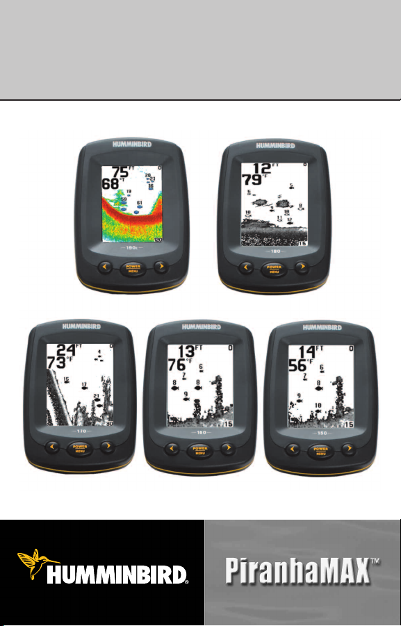
• To check the location planned for the control
head, test run the cables for the power and
transducer. See the installation section for
your transducer type in order to plan the
location of the transducer.
• The mounting surface should be stable
Figure 1
Figure 2
Connect the Power Cable to the Boat
A 6' long power cable is included to supply power to the control head. You
may shorten or lengthen the cable using 18 gauge multi-stranded copper wire.
CAUTION: Some boats have 24 or 36 Volt electric systems, but the control head
MUST be connected to a 12 VDC power supply.
enough to protect the control head from
excessive wave shock and vibration, and
should provide visibility while in operation.
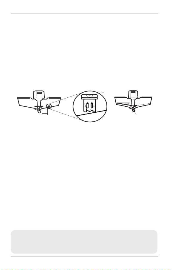
• Your PiranhaMAX™ may have one of two
different types of mounting bases, either a tilt
mounting base or a tilt and swivel mounting
base. The mounting area should allow
sufficient room for the unit to pivot freely, to
swivel if capable, and for easy removal and
installation (Figures 1 and 2).
The control head power cable can be connected to the electrical system of the
boat at two places: a fuse panel usually located near the console, or directly
to the battery.
NOTE: Make sure that the power cable is not connected to the control head at the
beginning of this procedure.
2
GROUNDGROUND
POSITIVEPOSITIVE
Control Head Installation
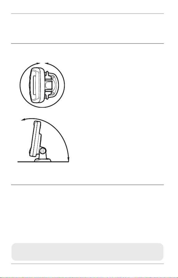
NOTE: Humminbird® is not responsible for over-voltage or over-current failures. The
control head must have adequate protection through the proper selection and
installation of a 1 amp fuse.
1a. If a fuse terminal is available, use
crimp-on type electrical connectors
(not included) that match the terminal
on the fuse panel. Attach the black
wire to ground (-), and the red wire to
positive (+) 12 VDC power (Figure 3).
Install a 1 amp fuse (not included) for
protection of the unit. Humminbird® is
Figure 3
not responsible for over-voltage of
over-current failures.
or...
1b. If you need to wire the control head
directly to a battery, obtain and install
an inline fuse holder and a 1 amp
fuse (not included) for the protection
of the unit (Figure 4). Humminbird® is
not responsible for over-voltage or
Inline Fuse Holder
Figure 4
over-current failures.
NOTE: In orderto minimize the potential for interferencewith other marine electronics,
a separate power source (such as a second battery) may be necessary.
3

Control Head Installation
Assembling the Control Head Base
Your control head base will either have a tilt mount or a tilt and swivel mount.
Refer to procedures A or B below to assemble and mount the control head
base.
A. If you have a tilt mount, follow these steps:
1. Set the tilt mount control head base in place on the mounting surface.
Mark the four mounting screw locations with a pencil or punch.
2. Set the base aside, and drill the four mounting screw holes using a
9/64" bit.
3. Proceed to Routing the Control Head Cables Under the Deck.
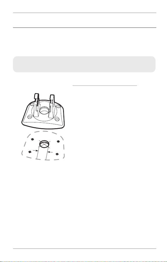
Tilt and Swivel Mount
Control Head Base Assembly
Mount Arms
B. If you have a tilt and swivel mount, follow
these steps:
1. Insert the mount arms into the base.
Then, hold the mount arms in place as
you turn the base upside down.
2. Insert the swivel ring into the base, with
Base
the countersink holes for the arm screws
facing out.
3. Secure the mount arms with the 4 #6
Swivel
Ring
screws provided (Figure 5). Hand tighten
only!
Countersink
Side Out
Arm Screws,
4 #6 x7/16"
Figure 5
4. Set the assembled control head base in
place on the mounting surface. Mark the
four mounting screw locations with a
pencil or punch.
5. Set the base aside, and drill the four
mounting screw holes using a 9/64" bit.
6. Proceed to Routing the Control Head
Cables Under the Deck.
4
3
/
4
”
1
9
m
m
Control Head Installation
Routing the Control Head Cables Under the Deck
Use the following steps to route the control head cables under the deck.
NOTE: Under the deck cable routing is not always possible. If this is not an option,
the cables should be routed and secured above deck.
NOTE: See the installation section for your transducer type in order to plan the
location of the transducer and cable route.
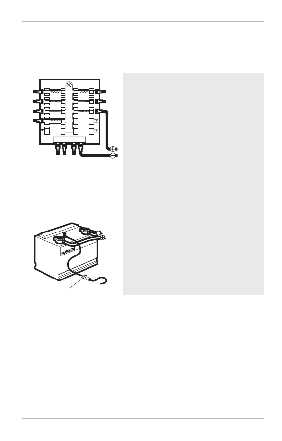
Tilt Mount or Tilt and Swivel Mount
Control Head Base
Figure 6
Tilt Mount or Tilt and Swivel Mount:
1a. Mark and drill a 3/4" hole as shown in
Figure 6. Route the cables through the
hole. The cables will exit through the
center hole on the control head base.
1b. If the cables cannot be routed directly
beneath the control head base, mark
and drill a 3/4" hole that will allow you
to run the cables close to the control
head base.
5

Control Head Installation
Attaching the Control Head to the Base
Follow these steps to attach the control head to the already-assembled base:
NOTE: The transducer cable and power cable should be routed prior to securing the
mounting bracket to the deck.
1. Apply marine-grade silicone sealant to the drilled holes for the
mounting bracket.
2. Place the mounting bracket on the mounting surface, aligning with the
drilled holes.
3. Insert the four #8 Phillips countersink wood screws into the mounting
holes and hand tighten only!
Pivot Knuckle
Gimbal Knob
Figure 7
Thumbknob Bolt
Mounting Holes
4. Insert the thumbknob bolt through the pivot knuckle on the control head
(Figure 7).
5. Align the pivot knuckle with the mount base arms and slide into place,
twisting slightly if necessary, until the unit is firmly seated.
6. Rotate the control head to the desired angle and hand tighten the
thumbknob bolt.
7. Thread the gimbal knob onto the pivot bolt and tighten.
6

Control Head Installation
Attaching the Cables to the Control Head
Follow thesestepsto attach the power and transducer cablesto the control head:
1. Matching the cable plugs to the shape
and orientation of the sockets, insert the
transducer and power cables into the
correct sockets on the control head
(Figure 8).
Power Temperature Transducer
Figure 8
You are now ready to install the transducer. See Transducer Installation
Overview and then find the section that refers to your transducer type.
2. With the control head in place, tilt
and/or swivel the unit through its full
range to make sure there is enough
cable slack for the unit to move freely.
Hand tighten the thumbknob bolt when
you achieve the desired position for the
control head.
7

Transducer Installation Overview
Transducer Installation Overview
The transducer can be installed on the transom of the boat, inside the hull, or
onto a trolling motor, depending on your transducer type. The type of
transducer you have will also determine how the cable will be routed. Go to
the section that describes your transducer, and follow the steps to position
and mount the transducer on your boat.
NOTE: Due to the wide variety of hulls, only general instructions are presented
in this installation guide. Each boat hull represents a unique set of requirements
that should be evaluated prior to installation. It is important to read the
instructions completely and understand the mounting guidelines before
beginning installation.
NOTE: If the included transducer will not work for your application, you may
exchange it, NEW and UNASSEMBLED, with mounting hardware included, for a
transducer appropriate for your application - often at very little or no charge
depending on the transducer. Call the Humminbird® Customer Resource Center at
1-800-633-1468 for details and pricing, or visit www.humminbird.com.
NOTE: In addition to the hardware supplied with your transducer, you will need a
powered hand drill and various drill bits, various hand tools, including a ruler or
straightedge,a level, a 12" plumb line (weighted string or monofilament line), marker
or pencil, safety glasses and dust mask, and marine-grade silicone sealant.
NOTE: Whendrilling holesin fiberglass hulls,it is best to start with a smallerbit and use
progressively largerdrill bitsto reducethe chance of chipping or flaking the outer coating.
8

Transom Transducer Installation
Transom Transducer Installation
Locating the Transducer Mounting Position
Turbulence: You must first determine the best location on the transom to
install the transducer. It is very important to locate the transducer in an area
that is relatively free of turbulent water.Consider the following to find the best
location with the least amount of turbulence:
Areas of Possible Turbulence
Rivets Strakes
Transom Hull
Figure 9
Stepped Hull
Step
Figure 10
• As the boat moves through the water,
turbulence is generated by the weight of
the boat and the thrust of the propeller(s)
- either clockwise or counter-clockwise. This
turbulent water is normally confined to
areas immediately aft of ribs, strakes or
rows of rivets on the bottom of the
boat, and in the immediate area of the
propeller(s). Clockwise propellers create
more turbulence on the port side. On
outboard or inboard/outboard boats, it is
best to locate the transducer at least 15" to
the side of the propeller(s) (Figure 11).
•
The best way to locate turbulence-free
water is to view the transom while the boat
is moving. This method is recommended if
maximum high-speed operation is a high
priority. If this is not possible, select a
location on the transom where the hull
forward of this location is smooth, flat and
free of protrusions or ribs (Figure 9).
• On boats with stepped hulls, it may be
possible to mount the transducer on the
Rib
step. Do not mount the transducer on the
transom behind a step to avoid popping the
transducer out of the water at higher
speeds; the transducer must remain in the
water for the control head to maintain the
sonar signal (Figure 10).
9
15”
Transom Transducer Installation
• If the transom is behind the propeller(s), it may be impossible to find an
area clear from turbulence, and a different mounting technique or
transducer type should be considered, such as an Inside the Hull
Transducer.
• If you plan to trailer your boat, do not mount the transducer too close to
trailer bunks or rollers to avoid moving or damaging the transducer
during loading and unloading of the boat.
• If high speed operation is critical, you may want to consider using an
In-Hull transducer instead of this Transom Mount transducer.
Level
Deadrise Angle
Find a turbulence-free location at least 15” from the propeller(s)
and not in line with trailer bunks or rollers. (Figure 11).
NOTE: The hydrodynamic shape of your transducer allows it to point straight down
without deadrise adjustment(Figure12).
Figure 12
NOTE: If you cannot find a transom mount location that will workfor your high-speed
application,find an In-Hull Transducer by contacting our Customer Resource Center at
either 1-800-633-1468or by visiting our website at www.humminbird.com.
10
 Loading...