


Ethernet Networking
Table of contents
 Loading...
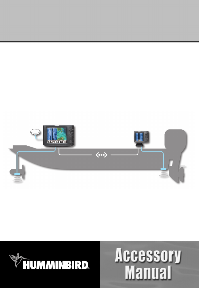
531906-1EN_A
Ethernet Networking
Installation & Operations Manual
Ethernet Networking
Installation & Operations Manual
GPS
Unit 1
Unit 2
HUMMINBIRD
®
ETHERNET

i
Thank You!
Thank you for choosing Humminbird®, America's #1 name in Fishfinders.
Humminbird® has built its reputation by designing and manufacturing
top-quality, thoroughly reliable marine equipment. Your Humminbird®
accessory is designed for trouble-free use in even the harshest marine
environment. In the unlikely event that your Humminbird® accessory does
require repairs, we offer an exclusive Service Policy - free of charge during the
first year after purchase, and available at a reasonable rate after the
one-year period. For complete details, see the separate warranty card included
with your accessory. We encourage you to read this operations manual
carefully in order to get full benefit from all the features and applications of
your Humminbird® product.
Contact our Customer Resource Center at 1-800-633-1468 or visit our
Web site at humminbird.com.
WARNING! This device should not be used as a navigational aid to prevent collision,
grounding, boat damage, or personal injury. When the boat is moving, water depth may
change too quickly to allow time for you to react. Always operate the boat at very slow
speeds if you suspect shallow water or submerged objects.
WARNING! The electronic chart in your Humminbird® unit is an aid to navigation
designed to facilitate the use of authorized government charts, not to replace them. Only
official government charts and notices to mariners contain all of the current information
needed for the safety of navigation, and the captain is responsible for their prudent use.
WARNING! Disassembly and repair of this electronic unit should only be performed by
authorized service personnel. Any modification of the serial number or attempt to repair
the original equipment or accessories by unauthorized individuals will void the warranty.
WARNING! This product contains chemicals known to the State of California to cause
cancer and/or reproductive harm.

NOTE: Some features discussed in this manual require a separate purchase, and some
features are only available on international models. Every effort has been made to clearly
identify those features. Please read the manual carefully in order to understand the full
capabilities of your model.
700 Series™, 800 Series™, 900 Series™, 1100 Series™, Cannon®, CannonLink™, Contour XD™,
Down Imaging™, DualBeam PLUS™, Fish ID+™, HumminbirdPC™, Humminbird®, InterLink™,
QuadraBeam PLUS™, RTS™ Window, Side Imaging®, SwitchFire™, Structure ID®, UniMap™,
WeatherSense®, WhiteLine™, and X-Press™ Menu are trademarked by or registered trademarks of
Humminbird®.
© 2010 Humminbird®, Eufaula AL, USA. All rights reserved.
NOTE: The Ethernet accessory is compatible with many Humminbird® models, and
every effort has been made to note the differences between the models and functions
throughout this manual. The illustrations in this manual may look different than your
display, but your model will operate in a similar way.
ii

Table of Contents
iii
Introduction 1
1. Installing an Ethernet Connection 2
2. Powering On 7
3. Configuring the Ethernet Network 8
Configuration Overview 8
Network Menu tab . . . . . . . . . . . . . . . . . . . . . . . . . . . . . . . . . . . . . . . . . . . . . . . 10
Customize the Unit Name 11
Open the Network Source Setup Dialog Box 12
Sonar Source Overview 13
Select a Sonar Source . . . . . . . . . . . . . . . . . . . . . . . . . . . . . . . . . . . . . . . . . . . . . 14
Change the Sonar Source . . . . . . . . . . . . . . . . . . . . . . . . . . . . . . . . . . . . . . . . . . 16
Temperature Source Overview 18
Select a Temperature Source . . . . . . . . . . . . . . . . . . . . . . . . . . . . . . . . . . . . . . . 19
Change the Temperature Source . . . . . . . . . . . . . . . . . . . . . . . . . . . . . . . . . . . . 22
GPS and Navigation Data Overview 24
Select a GPS Source . . . . . . . . . . . . . . . . . . . . . . . . . . . . . . . . . . . . . . . . . . . . . . 25
Change the GPS Source . . . . . . . . . . . . . . . . . . . . . . . . . . . . . . . . . . . . . . . . . . . 27
Share Navigation Data . . . . . . . . . . . . . . . . . . . . . . . . . . . . . . . . . . . . . . . . . . . . 28
Share Man Overboard (MOB) Navigation . . . . . . . . . . . . . . . . . . . . . . . . . . . . . 30
Restore Defaults (Setup Menu Tab) 32

Table of Contents
iv
Troubleshooting 33
Fishing System Doesn’t Power Up. . . . . . . . . . . . . . . . . . . . . . . . . . . . . . . . . . . 33
Fishing System Defaults to Simulator with a Transducer Attached. . . . . . . . . 34
Humminbird® Accessories 35
Contact Humminbird® 37

Introduction
This manual will guide you through the following network setup instructions:
1. Connect two Humminbird® units together
2. Power On
3. Configure your Humminbird® Ethernet Network
4. Share Navigation Data
Alarms, navigation, sonar data, waypoint management, and the menu
system are all affected by the Ethernet network settings. We
encourage you to read this manual completely so that you may
understand the full capabilites of your Humminbird® Ethernet network.
1
Introduction

1. Installing an Ethernet Connection
If your Humminbird® control head has a built-in Ethernet connector, the unit
can be connected to the Ethernet network. When you connect the units
together, data is shared between the two units.
Before you start, please note that the Ethernet network installation has the
following requirements:
• Update Software: If your network includes a legacy Humminbird®
model, download the latest software update from your account at
humminbird.com. Legacy models include 858c, 898c SI, 998c SI, 958c,
and 1100 Series™ units.
• Install the control heads and sources (GPS, transducers, temp/speed
accessories, etc.) for your Fishing System. See the equipment installation
guides for details.
• Purchase Ethernet Connection Cables (separate purchase required):
Your network configuration will determine which Humminbird®
connection cables you will need to purchase to connect the control
heads to the network (see the Ethernet Cable Information table).
2
Installation

NOTE: The AS EC [length]E cable is available in a variety of lengths. To purchase the
Ethernet Connect Cables or extension cables, visit our Web site at humminbird.com or
call our Customer Resource Center at 1-800-633-1468 for details.
Connect the Control Heads
1. Confirm that the control heads are powered off.
2. To install the Ethernet cables, see the connection information for
your network configuration as follows:
• Two 700 Series™ Units: see Section A.
• One 700 Series™ Unit & One 800/900/1100 Series™ Unit:
see Section B.
• Two 800, 900, or 1100 Series™ Units: see Section C.
NOTE: You may need to consult your control head installation guide for details.
NOTE: The AS EC [length]E cable is available in a variety of lengths. The following
instructions use AS EC 10E, but your cable part number may be different.
Ethernet Cable Information
(2) 700 Series™ Units
(1) 700 Series™ Unit &
(1) 800/900/1100 Series™ Unit
(2) 800, 900, or 1100 Series™ Units
Control Heads
(1) AS EC [length]E
(1) AS EC QDE + (1) AS EC [length]E
(2) AS EC QDE + (1) AS EC [length]E
Required Cables
3
Installation
A. Two 700 Series™ Units
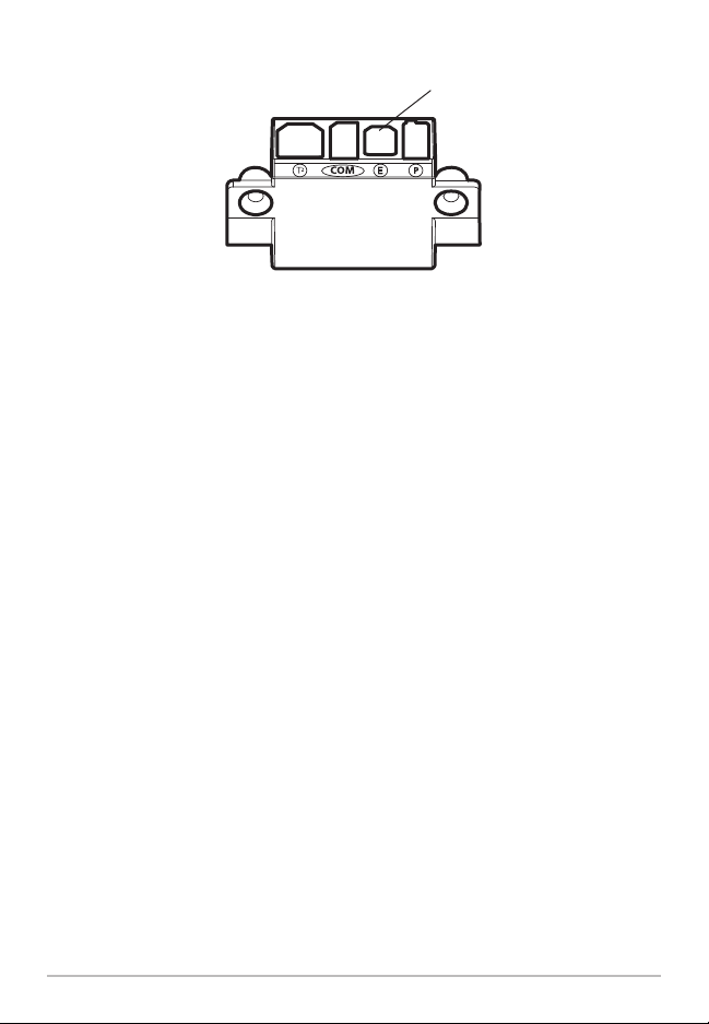
1. Insert the AS EC QDE Ethernet cable connector into the
Ethernet slot on the 700 Series™ cable collector. Repeat this
step for the second AS EC QDE cable.
NOTE: The 700 Series™ control head uses a cable collector for the Quick
Disconnect Mount and the In-Dash Mount. See your control head installation
guide for details.
2. Connect the AS EC 10E to each round connector on the
AS EC QDE cables.
3. Hand-tighten the screw nut(s) on each cable to secure the
connection. The connectors are keyed to prevent incorrect
installation, so be careful not to force the connectors.
B. One 700 Series™ Unit & One 800/900/1100 Series™ Unit
1. Insert the AS EC QDE Ethernet cable connector into the
Ethernet slot on the 700 Series™ cable collector.
NOTE: The 700 Series™ control head uses a cable collector for the Quick
Disconnect Mount or the In-Dash Mount. See your control head installation guide
for details.
2. Insert one end of the AS EC 10E cable into the Ethernet port on
the back of the 800/900/1100 Series™ control head. The
connectors are keyed to prevent incorrect installation, so be
careful not to force the connectors into the port.
700 Series™ Quick Disconnect Mount Cable Collector
Ethernet
4
Installation
3. Connect the AS EC QDE cable connector to the AS EC 10E cable
connector.
4. Hand-tighten the screw nut(s) on each cable to secure the
connection.
C. Two 800, 900, or 1100 Series™ Units
1. Insert one end of the AS EC 10E cable into the Ethernet port on
the back of the first control head. The connectors are keyed to
prevent incorrect installation, so be careful not to force the
connectors into the port.
2. Insert the other end of the AS EC 10E cable into the Ethernet
port on the second control head.
3. Hand-tighten the screw nut(s) on each cable to secure the
connection.
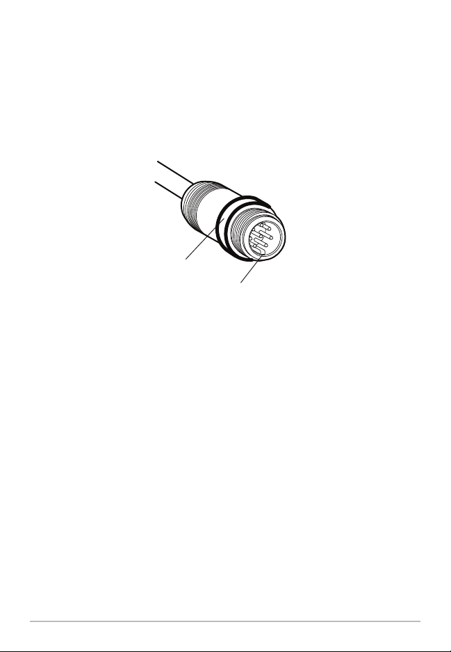
Hand-Tightening the Screw Nut
The connector is
keyed to prevent
incorrect installation.
Screw
Nut
5
Installation
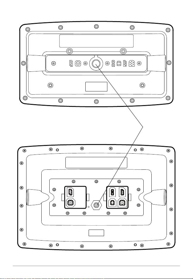
800/900 Series™ (rear view)
Ethernet Port
1100 Series™ (rear view)
6
Installation

2. Powering On
When you have installed an Ethernet network, the power on process is the
same as powering on a single control head, however, your transducer
connections will determine how the control head starts normal operation. It is
important to set up your network to use the correct sources.
Power On
1. Press the POWER/LIGHT key.
Operation Mode: If a transducer is attached to the control head,
Normal mode (for on-the-water use) will start automatically. This is the
default operation for powering on the control head, but the network
setup will vary with how you’ve set up the connections as follows:
• If a transducer is not attached to the control head, but there is
another transducer connected to the network, the control head
will detect the other transducer and use it to start Normal mode
automatically.
• If a transducer is not attached to the control head, but there is
more than one transducer connected to the network, follow the
on-screen instructions to choose a transducer source. See Select
a Sonar Source for more information.
NOTE: Also, see your control head operations manual for more information about
the Start-Up Options Menu.
2. Repeat steps 1 until all of the control heads in the network are
powered on. The Fishing System will detect the other control heads
and sources in the network.
NOTE: If you have an InterLink™ connected to the network, the Ethernet will disable
the InterLink™ because both network systems cannot be used at the same time.
If there is a transducer connected to only one of the control heads,
and you intend to share the transducer on the network, power on the
control head with the connected transducer first.
7
Powering On

3. Configuring the Ethernet Network
Set up your Humminbird® Ethernet Network using the following instructions,
including these topics:
1. Network Setup Overview
2. Customize the Unit Name
3. Select Data Sources (transducer, temperature, GPS receiver)
for each control head
4. Understand the Shared and Local Menu Settings
5. Share Navigation Data
Configuration Overview
Connected units can detect the other control heads and sources on the
network. When the units are connected for the first time, the sources
(transducer, temperature, and GPS) default to Local operation.
Local (default): The source reports data only to the connected control
head.
Shared: The source is set up to report data to both control heads in the
network so that they share the same data.
It is important to note that when a source is shared on the network,
the source’s data will be synchronized between units. The Menu
System and View Rotation will change to match the shared
source’s capabilities. Alarms and Navigation also operate
differently when they are shared. Review each source section to
understand how a shared source will affect your Fishing System.
8
Configuration Overview
Loading...