


788c and 788ci Combo
Operations Manual
531687-1_B

Thank You!
Thank you for choosing Humminbird®, America's #1 name in fishfinders. Humminbird® has built its reputation by designing and manufacturing top-quality, thoroughly reliable marine equipment. Your Humminbird® is designed for trouble-free use in even the harshest marine environment. In the unlikely event that your Humminbird® does require repairs, we offer an exclusive Service Policy - free of charge during the first year after purchase, and available at a reasonable rate after the one-year period. For complete details, see the separate warranty card included with your unit. We encourage you to read this operations manual carefully in order to get full benefit from all the features and applications of your Humminbird® product.
Contact our Customer Resource Center at either 1-800-633-1468 or visit our web site at www.humminbird.com.
WARNING! This device should not be used as a navigational aid to prevent collision, grounding, boat damage, or personal injury. When the boat is moving, water depth may change too quickly to allow time for you to react. Always operate the boat at very slow speeds if you suspect shallow water or submerged objects.
WARNING! Disassembly and repair of this electronic unit should only be performed by authorized service personnel. Any modification of the serial number or attempt to repair the original equipment or accessories by unauthorized individuals will void the warranty.
WARNING! This product contains chemicals known to the State of California to cause cancer and/or reproductive harm.
NOTE: Some features discussed in this manual require a separate purchase, and some features are only available on international models. Every effort has been made to clearly identify those features. Please read the manual carefully in order to understand the full capabilities of your model.
ENVIRONMENTAL COMPLIANCE STATEMENT: It is the intention of Humminbird® to be a responsible corporate citizen, operating in compliance with known and applicable environmental regulations, and a good neighbor in the communities where we make or sell our products.
WEEE DIRECTIVE: EU Directive 2002/96/EC “Waste of Electrical and Electronic Equipment Directive (WEEE)” impacts most distributors, sellers, and manufacturers of consumer electronics in the European Union. The WEEE Directive requires the producer of consumer electronics to take responsibility for the management of waste from their products to achieve environmentally responsible disposal during the product life cycle.

WEEE compliance may not be required in your location for electrical & electronic equipment (EEE), nor may it be required for EEE designed and intended as fixed or temporary installation in transportation vehicles such as automobiles, aircraft, and boats. In some European Union member states, these vehicles are considered outside of the scope of the Directive, and EEE for those applications can be considered excluded from the WEEE Directive requirement.
This symbol (WEEE wheelie bin) on product indicates the product must not be disposed of with other household refuse. It must be disposed of and collected for recycling and recovery of waste EEE. Humminbird® will mark all EEE products in accordance with the WEEE Directive. It is our goal to comply in the collection, treatment, recovery, and environmentally sound disposal of those products; however, these requirement do vary within European Union member states. For more information about where you should dispose of your waste equipment for recycling and recovery and/or your European Union member state requirements, please contact your dealer or distributor from
which your product was purchased.
ROHS STATEMENT: Product designed and intended as a fixed installation or part of a system in a vessel may be considered beyond the scope of Directive 2002/95/EC of the European Parliament and of the Council of 27 January 2003 on the restriction of the use of certain hazardous substances in electrical and electronic equipment.
Navionics® Gold, HotMaps™, and HotMaps Premium™ are registered trademarks of Navionics®. 700 Series™, Cannon®, CannonLink™, DualBeam PLUS™, Fish ID+™, Fishing GPS®, Humminbird®, HumminbirdPC™, InterLink™, QuadraBeam PLUS™, RTS™, RTS Window™, Structure ID®, Selective Fish ID+®, WeatherSense®, WhiteLine™, WideSide®, UniMap™, and X-Press™ Menu are trademarked by or registered trademarks of Humminbird®.
© 2008 Humminbird®, Eufaula AL, USA. All rights reserved.

Table of Contents |
|
How Sonar Works |
1 |
DualBeam PLUS™ Sonar .......................................................................................... |
3 |
QuadraBeam PLUS™ Sonar |
|
(with optional-purchase QuadraBeam PLUS™ transducer).............................................. |
4 |
WideSide® Sonar (with optional-purchase WideSide® transducer) .................................. |
5 |
Universal Sonar 2 (compatible with optional-purchase Minnkota trolling motors).............. |
5 |
How GPS and Cartography Work |
6 |
What’s On the Sonar Display |
8 |
Understanding the Sonar Display .......................................................................... |
10 |
Real Time Sonar (RTS™) Window .......................................................................... |
11 |
Freeze Frame and Active Cursor.............................................................................. |
12 |
Bottom Presentation................................................................................................ |
13 |
Views |
15 |
Sonar View .............................................................................................................. |
18 |
Sonar Zoom View .................................................................................................... |
19 |
200/83 kHz Split Sonar View .................................................................................. |
20 |
Big Digits View ........................................................................................................ |
21 |
Circular Flasher View .............................................................................................. |
22 |
Snapshot and Recording View................................................................................ |
23 |
Side Beam View (with optional-purchase QuadraBeam PLUS™ transducer).................... |
33 |
WideSide® View (with optional-purchase WideSide® transducer).................................. |
37 |
Bird's Eye View ........................................................................................................ |
38 |
Chart View................................................................................................................ |
39 |
Chart/Sonar Combo View........................................................................................ |
41 |
View Orientation ...................................................................................................... |
42 |
Viewing Cartography .............................................................................................. |
42 |
i

Table of Contents |
|
Introduction to Navigation |
45 |
Waypoints, Routes, and Tracks ............................................................................ |
46 |
Save, Edit, or Delete a Waypoint.......................................................................... |
47 |
Navigate to a Waypoint or Position...................................................................... |
49 |
Add a Waypoint Target or Trolling Grid ................................................................ |
50 |
Save, Edit, or Delete a Route ................................................................................ |
52 |
Save or Clear a Current Track................................................................................ |
53 |
Edit, Delete, or Hide Saved Tracks........................................................................ |
53 |
Man Overboard (MOB) Navigation ...................................................................... |
54 |
Using Your 700 Series™ Control Head |
56 |
Key Functions |
57 |
POWER/LIGHT Key .............................................................................................. |
57 |
VIEW Key .............................................................................................................. |
57 |
INFO Key ................................................................................................................ |
58 |
MENU Key ............................................................................................................ |
58 |
4-WAY Cursor Control Key .................................................................................. |
59 |
MARK Key.............................................................................................................. |
60 |
GOTO Key................................................................................................................ |
60 |
ZOOM (+/-) Key...................................................................................................... |
61 |
VIEW PRESET Keys................................................................................................ |
61 |
EXIT Key ................................................................................................................ |
62 |
Multi-Media Card (MMC)/SD Slot |
63 |
Adding Maps to Your Fishing System ................................................................ |
63 |
Updating Software ................................................................................................ |
64 |
Exporting Navigation Data .................................................................................... |
65 |
Accessory Bus |
66 |
ii

Table of Contents |
|
Powering On the Unit |
67 |
The Menu System |
68 |
Start-Up Options Menu |
69 |
Normal Operation .................................................................................................... |
70 |
Simulator ................................................................................................................ |
70 |
System Status ........................................................................................................ |
72 |
Self Test.................................................................................................................... |
72 |
Accessory Test.......................................................................................................... |
73 |
GPS Diagnostic View .............................................................................................. |
74 |
PC Connect (with optional-purchase PC Connect cable only).......................................... |
74 |
X-Press™ Menu |
75 |
Main Menu |
76 |
Quick Tips for the Main Menu .................................................................................... |
77 |
User Mode (Normal or Advanced) ................................................................................ |
78 |
Sonar X-Press™ Menu (Sonar views only) |
80 |
Side .......................................................................................................................... |
81 |
Sensitivity ................................................................................................................ |
82 |
Upper Range (Advanced: Sonar, Split Sonar, Big Digits and Circular Flasher views only)...... |
83 |
Lower Range .......................................................................................................... |
84 |
Side Beam Range (WideSide® transducer: WideSide® view only) .................................. |
85 |
Chart Speed ............................................................................................................ |
86 |
Quad Layout (with optional-purchase QuadraBeam PLUS™ Transducer, |
|
Side Beam View only) .............................................................................................. |
86 |
Bottom Lock (Sonar Zoom view only) .......................................................................... |
87 |
Bottom Range (Sonar Zoom view only when Bottom Lock is On).................................... |
87 |
Cancel Navigation (only when navigating).................................................................. |
88 |
iii

Table of Contents |
|
Navigation X-Press™ Menu (Navigation views only) |
89 |
Waypoint [Name] (Only with an active cursor on a waypoint) .................................... |
90 |
Cursor To Waypoint (Chart or Combo View only) ...................................................... |
91 |
Save Current Track ................................................................................................ |
91 |
Clear Current Track ................................................................................................ |
92 |
Save Current Route (only when Navigating) ............................................................ |
92 |
Skip Next Waypoint (only when Navigating) ............................................................ |
93 |
Cancel Navigation (only when Navigating) .............................................................. |
93 |
Cancel MOB Navigation (only when MOB Navigation is activated)............................ |
94 |
Remove Target (only if Target is Active) .................................................................... |
94 |
Remove Grid (only if Grid is Active)............................................................................ |
95 |
Sonar Window (Combo View only) .......................................................................... |
95 |
Waypoint [Name] (Most recently-created waypoint) .................................................. |
96 |
Snapshot and Recording X-Press™ Menu |
|
(Snapshot and Recording View only) |
97 |
Start Recording |
|
(optional-purchase MMC/SD Card, Snapshot and Recording View only) ...................... |
98 |
Stop Recording (optional-purchase MMC/SD Card only) ............................................ |
98 |
Delete Image |
|
(optional-purchase MMC/SD Card, Snapshot and Recording View only) ...................... |
99 |
Delete All Images |
|
(optional-purchase MMC/SD Card, Snapshot and Recording View only) ...................... |
99 |
Delete Recording |
|
(optional-purchase MMC/SD Card, Snapshot and Recording View only).................... |
100 |
Delete All Recordings |
|
(optional-purchase MMC/SD Card, Snapshot and Recording View only).................... |
100 |
Pings Per Second |
|
(optional-purchase MMC/SD Card, Snapshot and Recording View only).................... |
101 |
Playback Speed (optional-purchase MMC/SD Card, Snapshot and Recording View only).... |
102 |
Stop Playback (optional-purchase MMC/SD Card only) ............................................ |
103 |
iv

Table of Contents |
|
Alarms Menu Tab |
104 |
Depth Alarm .......................................................................................................... |
105 |
Fish ID Alarm.......................................................................................................... |
105 |
Low Battery Alarm ................................................................................................ |
106 |
Aux. Temp. Alarm (with optional-purchase temp. probe or Temp/Speed only) .............. |
106 |
Temp. Alarm .......................................................................................................... |
107 |
Off Course Alarm.................................................................................................... |
108 |
Arrival Alarm .......................................................................................................... |
108 |
Drift Alarm.............................................................................................................. |
109 |
Alarm Tone ............................................................................................................ |
109 |
Sonar Menu Tab |
110 |
Beam Select .......................................................................................................... |
111 |
Fish ID+™ .............................................................................................................. |
112 |
Fish ID Sensitivity .................................................................................................. |
113 |
Real Time Sonar (RTS™) Window ........................................................................ |
113 |
Bottom View .......................................................................................................... |
114 |
Zoom Width............................................................................................................ |
114 |
83 kHz Sensitivity (Advanced).................................................................................. |
115 |
455 kHz Sensitivity (Advanced: with QuadraBeam PLUS™ transducer)........................ |
116 |
WideSide® Sensitivity (Advanced: with WideSide® transducer) .................................. |
117 |
Depth Lines (Advanced) .......................................................................................... |
118 |
Surface Clutter (Advanced)...................................................................................... |
119 |
Noise Filter (Advanced) ............................................................................................ |
120 |
Max Depth (Advanced) ............................................................................................ |
120 |
Water Type (Advanced) ............................................................................................ |
121 |
Transducer Select .................................................................................................. |
121 |
v

Table of Contents |
|
Navigation Menu Tab |
122 |
Current Track........................................................................................................ |
123 |
Saved Tracks ........................................................................................................ |
123 |
Waypoints ............................................................................................................ |
125 |
Routes .................................................................................................................. |
127 |
Chart Orientation ................................................................................................ |
129 |
North Reference .................................................................................................. |
129 |
Waypoint Decluttering (Advanced) ...................................................................... |
129 |
Grid Rotation........................................................................................................ |
130 |
Trackpoint Interval .............................................................................................. |
130 |
Track Min Distance (Advanced) ............................................................................ |
131 |
Track Color Range................................................................................................ |
131 |
Map Datum (Advanced) ........................................................................................ |
132 |
Course Projection Line ........................................................................................ |
132 |
Export All Nav Data (Advanced) ............................................................................ |
132 |
Delete All Nav Data (Advanced)............................................................................ |
133 |
Continuous Navigation Mode ............................................................................ |
133 |
GPS Receiver Override (Advanced)........................................................................ |
134 |
Chart Menu Tab |
135 |
Chart Detail Level ................................................................................................ |
136 |
Map Borders ........................................................................................................ |
137 |
Lat/Lon Grid.......................................................................................................... |
137 |
Spot Soundings .................................................................................................... |
138 |
Navaids on Bird’s Eye View ................................................................................ |
138 |
Shaded Depth...................................................................................................... |
138 |
Chart Select.......................................................................................................... |
138 |
NVB Chart Preference ........................................................................................ |
139 |
Set Simulation Position (Advanced) ...................................................................... |
139 |
Set Map Offset (Advanced) .................................................................................. |
140 |
Clear Map Offset (Advanced) ................................................................................ |
140 |
vi

Table of Contents |
|
Setup Menu Tab |
141 |
Units - Depth.......................................................................................................... |
142 |
Units - Temp (International only) .............................................................................. |
142 |
Units - Distance...................................................................................................... |
142 |
Units - Speed.......................................................................................................... |
143 |
User Mode ............................................................................................................ |
143 |
Language (International only).................................................................................... |
143 |
Triplog Reset .......................................................................................................... |
144 |
Restore Defaults .................................................................................................... |
144 |
Select Readouts (Advanced, Sonar View only) .......................................................... |
145 |
Depth Offset (Advanced).......................................................................................... |
146 |
Aux. Temp. Offset (Advanced).................................................................................. |
147 |
Temp. Offset (Advanced).......................................................................................... |
147 |
Speed Calibration (Advanced, with Temp/Speed only)................................................ |
148 |
Local Time Zone (Advanced).................................................................................... |
148 |
Daylight Saving Time (Advanced)............................................................................ |
149 |
Position Format (Advanced) .................................................................................... |
149 |
Time Format (Advanced, International only)................................................................ |
150 |
Date Format (Advanced, International only)................................................................ |
150 |
Digits Format (Advanced) ........................................................................................ |
151 |
NMEA Output (Advanced) ...................................................................................... |
151 |
Sonar ...................................................................................................................... |
152 |
Views Menu Tab |
153 |
Accessories Menu Tab |
154 |
Using Screen Snapshot ........................................................................................ |
155 |
vii
Table of Contents |
|
Troubleshooting |
158 |
Fishing System Doesn’t Power Up...................................................................... |
158 |
Fishing System Defaults to Simulator with a Transducer Attached ................ |
158 |
Display Problems ................................................................................................ |
159 |
Finding the Cause of Noise ................................................................................ |
160 |
700 Series™ Fishing System Accessories |
161 |
Specifications |
163 |
Glossary |
164 |
Contact Humminbird® |
181 |
NOTE: Entries in this Table of Contents which list (International Only) are only available on products sold outside of the U.S. by our authorized International Distributors. It is important to note that products sold in the U.S. are not intended for resale in the international market. To obtain a list of authorized International Distributors, please visit our website at www.humminbird.com or contact our Customer Resource Center at 1-800-633-1468 to locate the distributor nearest you.
NOTE: Entries in this Table of Contents which list (with PC Connect Cable only) or (with Temp/Speed only) require the purchase of separate accessories. You can visit our website at www.humminbird.com to order these accessories online or contact our Customer Resource Center at 1-800-633-1468.
NOTE: Some features discussed in this manual require a separate purchase, and some features are only available on international models. Every effort has been made to clearly identify those features. Please read the manual carefully in order to understand the full capabilities of your model.
viii
How Sonar Works
Sonar technology is based on sound waves. The 700 Series™ Fishing System uses sonar to locate and define structure, bottom contour and composition, as well as depth directly below the transducer.
Your 700 Series™ Fishing System sends a sound wave signal and determines distance by measuring the time between the transmission of the sound wave and when the sound wave is reflected off of an object; it then uses the reflected signal to interpret location, size, and composition of an object.
Sonar is very fast. A sound wave can travel from the surface to a depth of 240 ft (70 m) and back again in less than 1/4 of a second. It is unlikely that your boat can “outrun“ this sonar signal.
SONAR is an acronym for SOund and NAvigation Ranging. Sonar utilizes precision sound pulses or “pings“ which are emitted into the water in a teardrop-shaped beam.
The sound pulses “echo“ back from objects in the water such as the bottom, fish, and other submerged objects. The returned echoes are displayed on the LCD screen. Each time a new echo is received, the old echoes are moved across the LCD, creating a scrolling effect.
1How Sonar Works
When all the echoes are viewed side by side, an easy to interpret “graph“ of the bottom, fish, and structure appears.
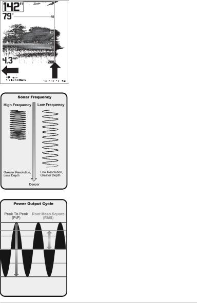
The sound pulses are transmitted at various frequencies depending on the application. Very high frequencies (455 kHz) are used for greatest definition but the operating depth is limited. High frequencies (200 kHz) are commonly used on consumer sonar and provide a good balance between depth performance and resolution. Low frequencies (83 kHz) are typically used to achieve greater depth capability.
The power output is the amount of energy generated by the sonar transmitter. It is commonly measured using two methods:
•Root Mean Square (RMS) measures power output over the entire transmit cycle.
•Peak to Peak measures power output at the highest points.
The benefits of increased power output are the ability to detect smaller targets at greater distances, ability to overcome noise, better high speed performance and enhanced depth capability.
How Sonar Works |
2 |
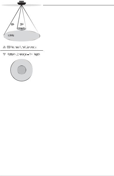
DualBeam PLUS™ Sonar
Your 700 Series™ Fishing System uses a 200/83 kHz DualBeam PLUS™ sonar system with a wide (60°) area of coverage. DualBeam PLUS™ sonar has a narrowly focused 20° center beam, surrounded by a second beam of 60°, expanding your coverage to an area equal to your depth. In 20 feet of water, the wider beam covers an area 20 feet wide. DualBeam PLUS™ sonar returns can be blended together, viewed separately, or compared side-by-side. DualBeam PLUS™ is ideal for a wide range of conditions - from shallow to very deep water in both fresh and salt water. Depth capability is affected by such factors as boat speed, wave action, bottom hardness, water conditions and transducer installation.
3How Sonar Works

35° |
60° |
20° |
35° |
455 kHz |
|
200 kHz |
455 kHz |
|
|
|
83 kHz


 90° Total Coverage


 Bottom Coverage =2 x Depth
QuadraBeam PLUS™ Sonar
(with optional-purchase QuadraBeam PLUS™
transducer)
Your 700 Series™ Fishing System also supports QuadraBeam PLUS™ sonar with the purchase of an additional QuadraBeam PLUS™ transducer. QuadraBeam PLUS™ sonar provides an extremely wide 90° area of coverage. QuadraBeam PLUS™ starts with two fan-shaped 35° 455 kHz Side Structure locating sonar beams to spot fish, bait, and structure to the left and right of the boat over an area of the bottom that’s always equal to twice your depth. For a detailed view below the boat, QuadraBeam PLUS™ uses DualBeam PLUS™ technology, with precision 20° and wide 60° beams. QuadraBeam PLUS™ finds more fish faster and can even tell you where to put your bait by showing if fish are to the left, right, or directly beneath your boat.
How Sonar Works |
4 |

WideSide® Sonar
(with optional-purchase WideSide®
transducer)
Your 700 Series™ Fishing System also supports WideSide® sonar with the purchase of an additional WideSide® transducer. The WideSide® transducer is a specialized "side-looking" transducer that is extremely useful for bank fishing or looking for bait fish in open water. The WideSide® transducer uses three different sonar elements that transmit signals to the left, right, and straight down from your boat. The downward beam is 200 kHz with a 24° area of coverage. This beam maintains a continuous digital depth readout from the bottom directly beneath your boat. The side beams are 455 kHz with a 16° area of coverage. The side-looking elements can be used independently or together to locate targets near the surface of the water on either side of your boat.
Universal Sonar 2
(compatible with optional-purchase Minnkota trolling motors)
Your 700 Series™ Fishing System supports Universal Sonar 2, a state-of-the- art, integrated and protected transducer that is built into the lower unit of Minnkota trolling motors. With Universal Sonar 2, all wiring is concealed inside the indestructible composite shaft—out of sight and out of harm’s way, with no clamps, ties, or exposed wires. Universal Sonar 2 features new temperature sensing and the performance of DualBeam PLUS™ technology (available with all Humminbird® DualBeam PLUS™ models). An expanded view and greater bottom detail gives you a totally new perspective of the water below, along with optimal sonar performance to help you find fish.
5How Sonar Works

How GPS and Cartography Work
Your 700 Series™ Fishing System also supports GPS and chartplotting. It uses GPS and sonar to determine your position, display it on a grid, and provide detailed underwater information. The Global Positioning System (GPS) is a satellite navigation system designed and maintained by the U.S. Department of Defense. GPS was originally intended for military use; however, civilians may also take advantage of its highly accurate position capabilities, typically within +/- 4.5 meters, depending on conditions. This means that 95% of the time, the GPS receiver will read a location within 4.5 meters of your actual position. Your GPS Receiver also uses information from WAAS (the Wide Area Augmentation System), EGNOS (the European Geostationary Navigation Overlay Service), and MSAS (the MTSAT Satellite Augmentation System) satellites if they are available in your area.
GPS uses a constellation of over 24 satellites that continually send radio signals to the earth. Your present position is determined by receiving signals from up to 16 satellites and measuring the distance from the satellites.
All satellites broadcast a uniquely coded signal once per second at exactly the same time. The GPS receiver on your boat receives signals from satellites that are visible to it. Based on time
differences between each received signal, the GPS receiver determines its distance to each satellite. With distances known, the GPS receiver mathematically triangulates its own position. With once per second updates, the GPS receiver then calculates its velocity and bearing.
How GPS and Cartography Work |
6 |

The GPS Receiver included with your 700 Series™ Fishing System allows you to combine easy-to-use FishingGPS® chartplotter and navigation capabilities with advanced fishfinding.
The following GPS functionality is currently supported by the 700 Series™ Fishing System when it is connected to the included GPS receiver:
•View current position
•View current track (breadcrumb trail)
•View precision speed and heading from your GPS receiver
•Save tracks, waypoints, and routes
•Travel a route and navigate from one waypoint to the next.
Your 700 Series™ supports Navionics® Gold, HotMaps™ and HotMaps™ Premium on MMC or SD card media. You can insert optional-purchase cards in the (MMC)/SD slots on your control head to access additional detailed maps. See Multi-Media Card (MMC)/SD Slot for more information.
NOTE: Your 700 Series™ supports Navionics® Gold, HotMaps™, and HotMaps™ Premium. Your 700 Series™ does not support Navionics® Classic Charts or Platinum™ Cartography.
Your unit also comes with a built-in UniMap™ with a more detailed map of North America (Domestic models) or a more detailed map of Europe and Southeast Asia, including Australia and New Zealand (International models).
Your 700 Series™ uses the GPS Receiver to determine the position of the boat automatically, and it uses the zoom level settings on a particular view to select the best chart to display. See Chart View: Viewing Cartography for more information.
7How GPS and Cartography Work

What’s On the Sonar Display
The 700 Series™ Fishing System can display a variety of useful information about
Depth - water depth; can be set to alarm when the water becomes too shallow.
Temperature - water surface temperature.
Timer - Elapsed time with Temp/Speed
Accessory or GPSReceiver.
Distance - Distance traveled with Temp/Speed
Accessory or GPSReceiver.
Average Speed - Average speed reading with
Temp/Speed Accessory or GPSReceiver.
Speed - if a Temp/Speed accessory or GPS Receiver is attached, the Fishing System can display the speed of the boat and can keep a Triplog of nautical or statute miles traveled.
Second Sonar Return - when the sonar signal bouncesbetweenthebottomandthesurfaceofthe water and back again. Use the appearance of the second return to determine bottom hardness. Hard bottomswillshowastrongsecondreturn,whilesoft bottomswillshowaveryweakoneornoneatall.
Cursor Dialog Box - indicates cursor depth on the display and the depth of the bottom directly below the cursor. The Latitude and Longitude of the cursor position, the distance to travel to the cursor position and the bearing to the cursor position is shown with a GPS receiver. A waypoint can be marked at the cursor position for later retrieval and use with a GPS receiver.
NOTE: Entries in this view that list (with Temp/Speed or GPS Receiver) are available if either device information from the GPS receiver will be displayed on the view.
What’s On the Sonar Display |
8 |
the area under and adjacent to your boat, including the following items:
High Sonar Intensity Return 
Thermoclines - layers of water with different temperatures that appear at different depths and different times of the year. A thermocline typically appears as a continuous band of many colors moving across the display at the same depth.
Bait Ball
Fish - the Fishing System displays fish as arches and/or fish icons, and can be set to alarm when a fish of a certain size is detected. When a target is detected, a Fish ID+™ symbol appears on the display with the depth displayed above it. The size of the symbol indicates the intensity of the sonar return. The unit will clearly show schools of Bait Fish as "clouds" of different shapes and sizes, depending on the number of fish and boat speed.
Cursor - available in Freeze Frame and can be positioned in the Sonar View to provide depthofasonarreturnandbottomdepthbelow the cursor.
RTS (Real Time Sonar) Window™
Structure - where fish may be hiding.
Low Sonar Intensity Return 
is connected to the 700 Series™ Fishing System. If both devices are connected, then only the
9What’s On the Sonar Display
The returned sonar echoes are displayed on the screen. As a new echo is received, the historical data scrolls across the screen.
Understanding the Sonar Display
It is important to understand the significance of the display. The display does not show a literal 3- dimensional representation of what is under the water. Each vertical band of data received by the control head and plotted on the display represents something that was detected by a sonar return at a particular time. As both the boat and the targets (fish) may be moving, the returns are only showing a particular segment of time when objects were detected, not exactly where those objects are in relation to other objects shown on the display.
What’s On the Sonar Display |
10 |

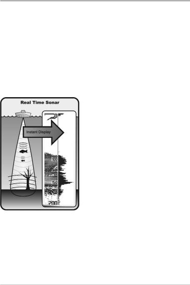
Real Time Sonar (RTS™) Window
A Real Time Sonar (RTS™) Window appears on the right side of the display in the Sonar View only. The RTS Window™ updates at the fastest rate possible for depth conditions and shows only the returns from the bottom, structure, and fish that are within the transducer beam. The RTS Window™ plots the depth and intensity of a sonar return (see Sonar Menu Tab: RTS Window™).
The Narrow RTS Window™ indicates the sonar intensity through the use of colors. Red indicates a strong return and blue indicates a weak return. The depth of the sonar return is indicated by the vertical placementofthereturnonthe display depth scale.
The Wide RTS Window™ indicates the sonar intensity through the use of a bar graph. The length of the plotted return indicates whether the return is weak or strong. The depth of the sonar return is indicated by the vertical placement of the return on the display depth scale. The Wide RTS Window™ does not use grayscale.
11 |
What’s On the Sonar Display |

Freeze Frame and Active Cursor
Freeze Frame & Active Cursor - Press any arrow on the 4-WAY Cursor Control key, and the screen will freeze and a cursor will be displayed. Use the 4-WAY Cursor Control key to move the cursor over a sonar return, and the depth of the sonar return will be displayed at the bottom of the screen in the cursor information box.
Instant Image Update - You can change a variety of sonar menu settings (such as Sensitivity or Upper Range), and the adjustments will be shown instantly on the screen. When combined with the Freeze frame feature, you can adjust and see the effects of many different sonar settings quickly and easily.
The RTS Window™ continues to update in Freeze Frame. Pressing EXIT will exit Freeze Frame, and the display will start to scroll. Freeze Frame is available in the Sonar, Sonar Zoom, and 200/83 kHz Split Sonar Views.
What’s On the Sonar Display |
12 |

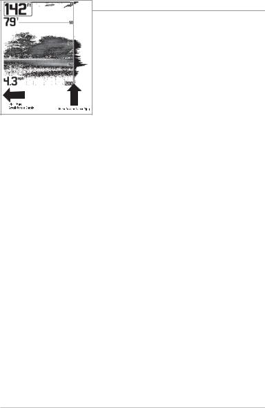
Bottom Presentation
As the boat moves, the unit charts the changes in depth on the display to create a profile of the Bottom Contour. The type of bottom can be determined from the return charted on the display. A Hard Bottom such as compacted sediment or flat rock appears as a thinner line across the display. A Soft Bottom such as mud or sand appears as a thicker line across the display. Rocky Bottoms have a broken, random appearance.
Bottom Contour Profile with RTS Window™
Rocky Bottom
Soft Bottom
Hard Bottom 
The sonar returns from the bottom, structure, and fish can be represented as either WhiteLine™ or Structure ID®. See Sonar Menu Tab: Bottom View for details on how to set the bottom view.
13 |
What’s On the Sonar Display |

Structure ID® represents weak returns in blue and strong returns in red.
WhiteLine™ highlights the strongest sonar returns in white, resulting in a distinctive outline. This has the benefit of clearly defining the bottom on the display.
What’s On the Sonar Display |
14 |

Views
The sonar and navigation information from your Fishing System is displayed on your screen in a variety of easy-to-read views. There are many views available on your Fishing System. When you press the VIEW key, the display cycles through the available views on your screen. When you press the EXIT key, the display cycles through the available views in reverse order.
When you first power up the control head, Sonar View will be the default view. You can display and hide any view to suit your fishing preferences.
Chart/Sonar
Combo View
Sonar
View
Sonar Zoom
View
Chart |
|
|
|
|
|
|
|
Sonar |
View |
|
|
|
|
|
|
|
View |
Bird’s Eye |
|
|
|
|
|
|
|
Big Digits |
View |
|
|
|
|
|
|
|
View |
GPS |
|
|
|
|
|
|
|
Circular Flasher |
|
|
|
|
|
|
|
||
Diagnostic |
|
|
|
|
|
|
|
View |
View |
|
|
|
|
|
|
|
|
Accessory |
|
|
|
|
|
|
|
Snapshot and |
Test View |
|
|
|
|
|
|
|
Recording View |
Self Test |
|
|
|
|
|
|
|
Side Beam |
View |
WideSide View |
View |
||||||
|
(optional |
|||||||
(optional |
QuadraBeam |
|
WideSide |
||
required) |
||
required) |
||
|
NOTE: When you change any menu settings that affect the sonar, the view will update immediately. You don't have to exit the menu to apply the change to the screen.
NOTE: Side Beam View and WideSide® View require the purchase of the QuadraBeam PLUS™ transducer for the Side Beam View and the WideSide® transducer for the WideSide® View. You can visit our web site at www.humminbird.com to order these accessories online or contact our Customer Resource Center at 1-800-633-1468.
15 |
Views |

To customize your views rotation:
You can choose which views are hidden or visible in your view rotation.
1.Press the MENU key twice to access the tabbed Main Menu, then press the RIGHT Cursor key until the Views tab is selected.
2.Press the UP or DOWN Cursor keys to select a View.
3.Press the LEFT or RIGHT Cursor keys to change the status of the view from Hidden to Visible or vice versa.
To program each PRESET key:
Another way to access your favorite views quickly is to store them on the VIEW PRESET keys. Instead of using the VIEW key to cycle through every view to find the one you want, you can program the VIEW PRESET keys to display a specific view immediately.
1.Press the VIEW key to cycle to the view you want to store.
2.Press and hold one of the VIEW PRESET keys for several seconds. A chime will indicate that the view has been saved. You can store up to three views, one on each key.
To change the Digital Readouts:
Each view displays digital readout information (such as speed or time), which varies with the view selected, the accessory attached, and whether or not you are navigating. The digital readouts on the Sonar View can be customized. See
Setup Menu Tab: Select Readouts for more information.
1.Press the MENU key twice to access the tabbed Main Menu, then press the RIGHT Cursor key until the Setup tab is selected.
2.Press the DOWN key to highlight Select Readouts, and press the RIGHT Cursor key to access the Select Readouts submenu.
NOTE: If the Select Readouts option does not appear under the Setup tab, change the User Mode to Advanced.
Views |
16 |

3.Press the UP or DOWN Cursor keys to select a Readout position, then press the RIGHT or LEFT Cursor keys to choose what will be displayed in that position. To hide the data window, select Off. (Course, Navigation, Off, Position, Speed, Temperature, Time+Date, Triplog, Voltage, Time, Aux Temp.)
The available views are shown here and described on the following pages.
Sonar views:
Sonar View
Sonar Zoom View
200/83 kHz Split Sonar View
Big Digits View
Circular Flasher View
Snapshot and Recording View
Side Beam View
(with optional-purchase
QuadraBeam PLUS™ transducer)
WideSide® View
(with optional-purchase WideSide® transducer)
Self Test View
(see Start-Up Options Menu)
Accessory Test View
(see Start-Up Options Menu)
GPS Diagnostic View
(see Start-Up Options Menu)
Navigation views:
Bird’s Eye View
Chart View
Chart/Sonar Combo View
17 |
Views |
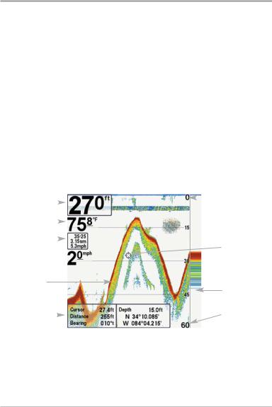
Sonar View
Sonar View presents a historical log of sonar returns. The most recent sonar returns are charted on the right side of the window. As new information is received, the historical information scrolls left across the display.
•Upper and Lower Depth Range numbers indicate the distance from the surface of the water to a depth range sufficient to show the bottom.
•Depth is automatically selected to keep the bottom visible on the display, although you can adjust it manually as well (see Sonar X-Press™ Menu).
•Digital Readouts shown on the display will change based on the Select Readouts settings or the optional-purchase accessories attached (see
Setup Menu Tab: Select Readouts).
•Freeze Frame - Use the 4-WAY Cursor Control key to freeze the display and move the cursor over a sonar return. The depth of the sonar return will be displayed at the bottom of the screen in the cursor information box.
Sonar View
Depth |
|
|
|
|
|
|
|
|
|
Upper Depth |
|
|
|
|
|
|
|
|
|
|
|||
|
|
|
|
|
|
|
|
Range |
|||
|
|
|
|
|
|
|
|
|
|
|
|
Temperature |
|
|
|
|
|
|
|
|
|||
|
|
|
|
|
|
||||||
Triplog |
|
|
|
|
|
Cursor |
|||||
|
|
|
|
||||||||
|
|
|
|
|
|
|
|
|
|
|
|
Sonar History |
|
|
|
|
|||||||
Window |
|
|
|
RTS Window™ |
|||||||
Cursor |
|
|
|
|
|
|
|
|
|
|
Lower Depth |
|
|
|
|
|
|||||||
Dialog Box |
|
|
|
Range |
|||||||
|
|
|
|
|
|
|
|
|
|
|
|
NOTE: If the Depth number is flashing, it means that the unit is having trouble locating the bottom. This usually happens if the water is too deep, the transducer is out of the water, the boat is moving too fast, or for any other reason that the unit can’t accurately receive continuous data.
Views |
18 |
 Loading...