


531440-1_B - HDR610 Manual_Eng.qxd 10/12/2005 11:05 AM Page 1
Humminbird® HDR 610
Installation and
Operations Manual
531440-1_B

531440-1_B - HDR610 Manual_Eng.qxd 10/12/2005 11:05 AM Page 2
THANK YOU!
Thank you for choosing Humminbird®, America's #1 name in fishfinders. Humminbird® has built its reputation by designing and manufacturing top-quality, thoroughly reliable marine equipment.
Your Humminbird® is designed for trouble-free use in even the harshest marine environment. In the unlikely event that your Humminbird® does require repairs, we offer an exclusive Service Policy - free of charge during the first year after purchase, and available at a reasonable rate after the one-year period. For complete details, see the Warranty section included in this manual.
Contact our Customer Resource Center at either 1-800-633-1468 or visit our website at www.humminbird.com.
© 2005 Humminbird®, Eufaula AL, USA. All rights reserved.
TABLE OF CONTENTS |
|
|
How Sonar Works |
4 |
|
Installation Overview |
5 |
|
Installing the HDR 610 ............................................................................................................ |
6 |
|
1. |
Locating the HRD 610 Mounting Position.......................................................................... |
7 |
2. |
Cutting the Mounting Hole ................................................................................................ |
7 |
3. |
Customizing and Assembling the HDR 610........................................................................ |
7 |
4. |
Installing the HDR 610 ........................................................................................................ |
9 |
5. |
Installing the Buzzer ............................................................................................................ |
9 |
6. |
Connecting the Transducer Cable .................................................................................... |
10 |
7. |
Connecting to the Power Supply ...................................................................................... |
10 |
Transducer Installation |
11 |
|
Transom Transducer Installation............................................................................................ |
11 |
|
1. |
Locating the Transducer Mounting Position .................................................................. |
11 |
2. |
Mounting the Bracket ...................................................................................................... |
12 |
3. |
Transducer Assembly ........................................................................................................ |
12 |
4. |
Mounting the Transducer Assembly to the Transom ...................................................... |
13 |
5. |
Running Position Adjustment .......................................................................................... |
13 |
6. |
Routing the Transducer Cable .......................................................................................... |
14 |
7. |
Final Testing........................................................................................................................ |
15 |
Inside the Hull Transducer Installation ................................................................................ |
15 |
|
1. |
Locating the Transducer Mounting Position .................................................................... |
16 |
2. |
Trial Installation.................................................................................................................. |
16 |
3. |
Routing the Cable .............................................................................................................. |
17 |
4. |
Permanently Mounting the Transducer............................................................................ |
17 |
Trolling Motor Transducer Installation...................................................................................... |
18 |
|
Trolling Motor Transducer Options........................................................................................ |
18 |
|
Test and Finish the Installation |
19 |
|
Inside the Hull Mounting, Puck Transducers Only |
20 |
|
1. |
Locating the Transducer Mounting Position .................................................................... |
20 |
2. |
Trial Installation.................................................................................................................. |
20 |
3. |
Routing the Cable .............................................................................................................. |
21 |
4. |
Permanently Mounting the Transducer............................................................................ |
21 |
Operating the HDR 610 |
23 |
|
What's on the Display ................................................................................................................ |
23 |
|
Key Functions .............................................................................................................................. |
23 |
|
Shallow Alarm ............................................................................................................................ |
24 |
|
Deep Alarm.................................................................................................................................. |
24 |
|
Units |
............................................................................................................................................ |
25 |
Keel Offset .................................................................................................................................. |
26 |
|
1 |
2 |
531440-1_B - HDR610 Manual_Eng.qxd 10/12/2005 11:05 AM Page 4
Maintenance |
28 |
HDR 610 Maintenance .............................................................................................................. |
28 |
Transducer Maintenance............................................................................................................ |
28 |
Troubleshooting |
28 |
HDR 610 Doesn't Power Up........................................................................................................ |
29 |
No Bottom Reading on the Display .......................................................................................... |
29 |
No Continuous Depth Display in Very Shallow Water.............................................................. |
29 |
Screen Fades, Images are Not Sharp........................................................................................ |
29 |
Bottom Reading Disappears During a Hard Turn...................................................................... |
29 |
1-Year Limited Warranty |
30 |
Humminbird® Service Policy |
30 |
Returning Your Unit for Service.................................................................................................. |
31 |
Specifications |
32 |
Contact Humminbird® |
33 |
Transom Mount Transducer Mounting Template |
34 |
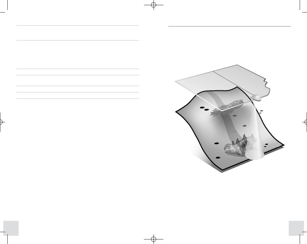
HOW SONAR WORKS
Sonar technology is based on sound waves. The HDR 610 Digital Depth Gauge uses sonar to determine depth directly below the transducer. Your HDR 610 Digital Depth Gauge consists of two components: the HDR 610 sonar unit and the transducer. The sonar unit contains the transmitter and receiver, as well as the user controls and display. The transducer is mounted beneath the water surface and converts electrical energy from the transmitter into mechanical pulses or sound waves. The transducer also receives the reflected sound waves and converts them back into electrical signals for display on the sonar unit.
Sonar is very fast. A sound wave can travel from the surface to a depth of 240 ft (70 m) and back again in less than 1/4 of a second. It is unlikely that your boat can "outrun" this sonar signal.
3 |
4 |

531440-1_B - HDR610 Manual_Eng.qxd 10/12/2005 11:05 AM Page 6
INSTALLATION OVERVIEW
Before you start installation, we encourage you to read these instructions carefully in order to get the full benefit from your HDR 610 Digital Depth Gauge. You will install your HDR 610 depthsounder first, then your transducer. When you are done with both of these installation tasks, you should perform a final installation test before operating your HDR 610.
Please make sure that the following parts are included for your depthsounder:
•HDR 610 depthsounder
•"U" bracket and mounting hardware
•2 cable ties.
Also, please make sure the following parts are included for your transducer:
•Transom mount or Puck transducer with 20' of cable
•Transducer mounting hardware kit.
In addition to the hardware supplied, you will need the following for installation and operation:
•Powered hand drill and various drill bits, including a 2 1/8" hole saw, if your boat does not have an existing gauge hole
•Phillips-head and flat-head screwdrivers
•Ruler or measuring tape
•Pen or pencil
•12 Volt power source (your boat's battery)
•Marine-grade silicone sealant (for sealing drilled holes)
•Two-part, slow-cure epoxy (for inside-the-hull transducer installation only).
NOTE: If you are wiring directly to the boat's battery, you will also need a 1 Amp fuse and a fuse holder.
INSTALLING THE HDR 610
Before installing the HDR 610, make sure you have the following parts:
•HDR 610 depthsounder
•"U" bracket and mounting hardware
•2 cable ties.
Perform the following high-level steps by following the instructions in each numbered section to install the HDR 610 depthsounder:
1.Locating the HRD 610 mounting position
2.Cutting the mounting hole
3.Customizing and assembling the HDR 610
4.Installing the HDR 610
5.Installing the buzzer
6.Connecting the transducer cable
7.Connecting to the power supply.
5 |
6 |
531440-1_B - HDR610 Manual_Eng.qxd 10/12/2005 11:05 AM Page 8
1. Locating the HDR 610 Mounting Position
You must select an appropriate mounting location for the HDR 610. Consider different positions on the console or deck of the boat. Remember that the cables for the transducer and power must reach the mounting location. Extension cables are available.
The mounting surface should be visible to the boat operator and adequately supported to protect the HDR 610 from excessive wave shock and vibration. Allow at least 2" clearance at the back, sides, and top of the unit for connection, air flow, and ease of installation and removal.
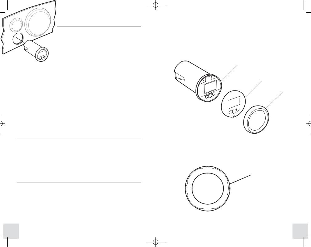
2.Carefully line up the notch on the bottom of the overlay with the tab at the bottom of the face of the HDR 610, then press the overlay into place so that all buttons and the display show through.
3.The bezel is keyed to fit only one way onto the front of the HDR 610. There are two opposing sets of tabs on the inside of the bezel: two wide tabs, and two tabs with slots in them. Find the tab that has the asymmetrical slots (refer to the illustration) and push the bezel onto the front of the HDR 610 according to the illustration.
HDR 610
Overlay
Bezel
2. Cutting the Mounting Hole
Once you have selected your mounting location, perform the following steps:
1.Mark the desired mounting location, then drill a pilot hole.
2.Drill a 2 1/8" diameter hole using a hole saw and hand drill. This is a standard hole saw readily available for rental or purchase. If you prefer, any marine service shop can perform this task.
3.Customizing and Assembling the HDR 610
Your HDR 610 comes with both black and white bezels, and both black and white overlays. You must select one color for the bezel, and another color for the overlay, and perform the following assembly steps:
1.Peel off the protective backing from the overlay, being careful not to let the adhesive touch anything prematurely.
WARNING: In order to provide a lasting, waterproof bond, the overlay adhesive is extremely sticky, and therefore you will NOT be able to re-position it once you have stuck it onto the face of the HDR 610.
Asymmetrical tabs on bezel
7 |
8 |

531440-1_B - HDR610 Manual_Eng.qxd 10/12/2005 11:05 AM Page 10
4. Installing the HDR 610
Once you have your mounting hole cut, perform the following steps:
1.Insert the HDR 610 from the front of the panel.
2.Install the "U" bracket and wingnut from the rear of the panel, and make sure that the face of the HDR 610 is oriented correctly, so that the top of the unit is at the top of the hole.
NOTE: If the panel into which you are mounting the unit is greater than 1/4" thick, the "U" bracket may appear too long. You may modify the "U" bracket by using pliers to break the legs of the bracket at the score lines. Shorten the bracket in gradual stages to avoid making it too short.
3.Tighten the wingnut to secure the installation.
5.Installing the Buzzer
Once the unit is mounted in the dash, secure the buzzer either to the metal bracket or to a nearby wire bundle using the cable ties included.
6. Connecting the Transducer Cable
Connect the transducer cable to the transducer connector on the HDR 610.
NOTE: The connector is keyed to prevent reverse installation, so be careful not to force the plug into the connector the wrong way.
7. Connecting to the Power Supply
Use the following information to connect your HDR 610 to an appropriate power supply:
•If your boat has an electrical system, there is probably a fuse panel in the console area that can be used to attach the HDR 610 power cable.
•If a fuse terminal is available, use crimp-on type electrical connectors (not included) that match the terminal on the fuse panel, and attach the black wire to ground, and the red wire to 12 VDC power. You must use a 1-Amp fuse in the connection.
•36" of power cable is included; you may shorten or lengthen this cable using 18-gauge, multi-strand copper wire.
Inline Fuse
Holder
CAUTION: Some boats have 24 or 36 Volt electrical systems. Make sure that your HDR 610 is connected to a 12 VDC power supply. Use a voltage conditioner for variable inputs.
•If you must wire the HDR 610 directly to a battery, make sure that you install an in-line fuse holder and a 1-Amp fuse (not included) for the protection of the unit. Humminbird® is not responsible for over-voltage or over-current failures.
9 |
10 |
 Loading...