


PiranhaMAX 143,153, and 180
Installation and Operations Manual
532044-1_B

Thank You!
Thank you for choosing Humminbird®,the #1 name in fishfinders. Humminbird® has built its reputation by designing and manufacturing top-quality, thoroughly reliable marine equipment. Your Humminbird® is designed for trouble-free use in even the harshest marine environment. In the unlikely event that your Humminbird® does require repairs, we offer an exclusive Service Policy-free of charge during the first year after purchase,and available at a reasonable rate after the one-year period. For complete details, see the Warranty section of this manual. We encourage you to read this installation and operations manual carefully in order to get full benefit from all the features and applications of your Humminbird® product.
Contact our Customer ResourceCenter at 1-800-633-1468 or visit our Web site at humminbird.com. The following models are covered in this manual:
•PiranhaMAX 143 - Single Beam, 160 V x 128 H MonochromeDisplay
•PiranhaMAX 153 - Dual Beam, 160 V x 128 H MonochromeDisplay
•PiranhaMAX 180 - Tri Beam, 240 V x 160 H Monochrome Display
WARNING! This device should not be used as a navigational aid to prevent collision, grounding, boat damage, or personal injury. When the boat is moving, water depth may change too quickly to allow time for you to react. Always operate the boat at very slow speeds if you suspect shallow water or submerged objects.
WARNING! Disassembly and repair of this electronic unit should only be performed by authorized service personnel. Any modification of the serial number or attemptto repair the original equipment or accessories by unauthorized individuals will void the warranty.
WARNING! Do not travel at high speed with the unit cover installed. Remove the unit cover before traveling at speeds above 20 mph.
WARNING! This product contains chemicals known to the State of California to cause cancer and/or reproductive harm.
NOTE: Some features discussed in this manual require a separate purchase, and some featuresare only availableon internationalmodels. Every effort has been made to clearly identify those features. Please read the manual carefully in order to understandthe full capabilitiesof your model.
NOTE: To purchase accessories for your fishfinder, visit our Web site at humminbird.comor contact our Customer Resource Center at 1-800-633-1468.
i

NOTE: The proceduresand features described in this manual are subject to change without notice. This manual was written in English and may have been translatedto another language. Humminbird® is not responsible for incorrect translations or discrepanciesbetween documents.
NOTE: Illustrationsin this manual may not look the same as your product, but your unit will function in the same way.
ATTENTION INTERNATIONAL CUSTOMERS: Products sold in the U.S. are not intended for use in the international market. Humminbird® international units provide international features and are designed to meet country and regional regulations. Languages, maps, time zones, units of measurement, and warranty are examples of features that are customized for Humminbird® international units purchased through our authorized international distributors.
To obtain a list of authorizedinternationaldistributors,please visit our Web site at humminbird.com or contact our Customer Resource Center at (334) 687-6613.
Humminbird®, Fish ID+™, Structure ID®, and WhiteLine™ are trademarked by or registered trademarks of Johnson Outdoors Marine Electronics, Inc.
Baekmuk Batang, Baekmuk Dotum, Baekmuk Gulim, and Baekmuk Headline are registered trademarks owned by Kim Jeong-Hwan.
© 2012 Johnson Outdoors Marine Electronics, Inc. All rights reserved.
ii

Table of Contents |
|
Installation Overview |
1 |
Control Head Installation |
2 |
Determine Where to Mount........................................................................ |
2 |
Connect the Power Cable to the Boat ...................................................... |
2 |
Assembling the Control Head Base ............................................................ |
4 |
Routing the Control Head Cables Under the Deck .................................... |
5 |
Attaching the Control Head to the Base .................................................... |
6 |
Attaching the Cables to the Control Head.................................................. |
7 |
Transducer Installation Overview |
8 |
Transom Transducer Installation |
8 |
Locating the Transducer Mounting Position .............................................. |
8 |
Preparing the Mounting Location ............................................................ |
10 |
Assembling the Transducer and Initial Mounting .................................... |
12 |
Routing the Cable...................................................................................... |
16 |
Test and Finish the Installation ................................................................ |
18 |
Inside the Hull Transducer Installation |
20 |
Determine the Transducer Mounting Location ........................................ |
21 |
Trial Installation ........................................................................................ |
22 |
Route the Cable ........................................................................................ |
23 |
Permanently Mount the Transducer ........................................................ |
23 |
Trolling Motor Transducer Installation |
24 |
Powering ON and OFF |
25 |
What You See On the Display |
26 |
PiranhaMAX Sonar Technology |
28 |
Single Beam Sonar .................................................................................... |
29 |
Dual Beam Sonar ...................................................................................... |
29 |
Tri Beam Sonar .......................................................................................... |
29 |
iii

Table of Contents |
|
The Menu System |
30 |
Light (Setting Not Saved in Memory) ........................................................ |
30 |
Sensitivity (Setting Saved in Memory) ...................................................... |
30 |
Depth Range (Setting Not Saved in Memory) .......................................... |
31 |
Zoom (Setting Not Saved in Memory)........................................................ |
31 |
Chart Speed (Setting Saved in Memory) .................................................. |
32 |
Fish Alarm (Setting Saved in Memory) ...................................................... |
32 |
Depth Alarm (Setting Saved in Memory) .................................................. |
32 |
Filter (Setting Saved in Memory) .............................................................. |
33 |
Setup Menu (Setting Not Saved in Memory) ............................................ |
33 |
Contrast (Setting Saved in Memory) .................................................... |
33 |
Fish ID+™ (Setting Saved in Memory) ................................................ |
34 |
Bottom View (Setting Saved in Memory).............................................. |
34 |
Battery Alarm (Setting Saved in Memory)............................................ |
36 |
Language (Setting Saved in Memory, International Only).................... |
36 |
Units (Setting Saved in Memory, International Only) .......................... |
36 |
Maintenance |
37 |
Troubleshooting |
38 |
International Purchases |
41 |
1-Year Limited Warranty |
42 |
Humminbird® Service Policy |
43 |
Returning Your Unit for Service |
44 |
Specifications |
45 |
Contact Humminbird® |
47 |
NOTE:Entriesin this Tableof Contentswhichlist (InternationalOnly)are only available on productssold outside of the U.S. by our authorizedInternationalDistributors.It is important to note that products sold in the U.S. are not intended for resale in the internationalmarket. To obtain a list of authorized InternationalDistributors,please visit our Web site at humminbird.comor contact our Customer Resource Center at 1-800-633-1468to locatethe distributornearestyou.
iv


Installation Overview
Installation Overview
Before you start installation, we encourage you to read these instructions carefully in order to get the full benefit from your PiranhaMAX.
There are three basic installation tasks that you must perform for the PiranhaMAX:
•Installing the control head
•Installing the transducer
•Testing the complete installation and locking the transducer position.
1
Control Head Installation
Control Head Installation
Determine Where to Mount
Begin the installation by determining where to mount the control head. Consider the following to determine the best location:
Figure 1
Figure 2
•To check the location planned for the control head, test run the cables for the power and transducer. See the installation section for your transducer type in order to plan the location of the transducer.
•The mounting surface should be stable enough to protect the control head from excessive wave shock and vibration, and should provide visibility while in operation.
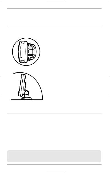
•Your PiranhaMAX may have one of two different types of mounting bases, either a tilt mounting base or a tilt and swivel mounting base. The mounting area should allow
sufficient room for the unit to pivot freely, to swivel if capable, and for easy removal and installation (Figures 1 and 2).
Connect the Power Cable to the Boat
A 6' long power cable is included to supply power to the control head. You may shorten or lengthen the cable using 18 gauge multi-stranded copper wire.
CAUTION! Some boats have 24 or 36 Volt electric systems, but the control head
MUST be connected to a 12 VDC power supply.
The control head power cable can be connected to the electrical system of the boat at two places: a fuse panel usually located near the console, or directly to the battery.
NOTE: Make sure that the power cable is not connected to the control head at the beginning of this procedure.
2

Control Head Installation
NOTE: Humminbird® is not responsible for over-voltage or over-current failures. The control head must have adequate protection through the proper selection and installation of a 1 amp fuse.
POSITIVE |
GROUND |
Figure 3
Inline Fuse Holder
Figure 4
1a. If a fuse terminal is available, use crimp-on type electrical connectors (not included) that match the terminal on the fuse panel. Attach the black wire to ground (-), and the red wire to positive (+) 12 VDC power (Figure 3). Install a 1 amp fuse (not included) for protection of the unit. Humminbird® is not responsible for over-voltage or over-current failures.
or...
1b. If you need to wire the control head directly to a battery, obtain and install an inline fuse holder and a 1 amp fuse (not included) for the protection of the unit (Figure 4). Humminbird® is not responsible for over-voltage or over-current failures.
NOTE:In order to minimizethe potentialfor interferencewith other marineelectronics, a separate power source (such as a second battery) may be necessary.
3
Control Head Installation
Assembling the Control Head Base
Your control head base will either have a tilt mount or a tilt and swivel mount. Refer to procedures A or B below to assemble and mount the control head base.
A.If you have a tilt mount, follow these steps:
1.Set the tilt mount control head base in place on the mounting surface. Mark the four mounting screw locations with a pencil or punch.
2.Set the base aside, and drill the four mounting screw holes using a 9/64" bit.
3.Proceed to Routing the Control Head Cables Under the Deck.
Tilt and Swivel Mount
Control Head Base Assembly


 Mount Arms
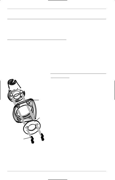
B.If you have a tilt and swivel mount, follow these steps:
1.Insert the mount arms into the base. Then, hold the mount arms in place as you turn the base upside down.
Base
Swivel
Ring
Countersink
Side Out 
Arm Screws,
4 #6 x7/16"
Figure 5
2.Insert the swivel ring into the base, with the countersink holes for the arm screws facing out.
3.Secure the mount arms with the four #6 screws provided (Figure 5). Hand tighten only!
4.Set the assembled control head base in place on the mounting surface. Mark the four mounting screw locations with a pencil or punch.
5.Set the base aside, and drill the four mounting screw holes using a 9/64" bit.
6.Proceed to Routing the Control Head Cables Under the Deck.
4
Control Head Installation
Routing the Control Head Cables Under the Deck
Use the following steps to route the control head cables under the deck.
NOTE: Under the deck cable routing is not always possible. If this is not an option, the cables should be routed and secured above deck.
NOTE: See the installation section for your transducer type in order to plan the location of the transducer and cable route.
Tilt Mount or Tilt and Swivel Mount Tilt Mount or Tilt and Swivel Mount:
Control Head Base
1a. Mark and drill a 3/4" hole as shown in Figure 6. Route the cables through the hole. The cables will exit through the center hole on the control head base.
1b. If the cables cannot be routed directly beneath the control head base, mark and drill a 3/4" hole that will allow you to run the cables close to the control head base.

 3/4” 19 mm
Figure 6
5

Control Head Installation
Attaching the Control Head to the Base
Follow these steps to attach the control head to the already-assembled base:
NOTE: The transducer cable and power cable should be routed prior to securing the mounting bracket to the deck.
1.Apply marine-grade silicone sealant to the drilled holes for the mounting bracket.
2.Place the mounting bracket on the mounting surface, aligning with the drilled holes.
3.Insert the four #8 Phillips countersink wood screws into the mounting holes and hand tighten only!
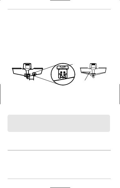
Pivot Knuckle
Thumbknob Bolt
Gimbal Knob
Figure 7 |
Mounting Holes |
4.Insert the thumbknob bolt through the pivot knuckle on the control head (Figure 7).
5.Align the pivot knuckle with the mount base arms and slide into place, twisting slightly if necessary, until the unit is firmly seated.
6.Rotate the control head to the desired angle and hand tighten the thumbknob bolt.
7.Thread the gimbal knob onto the pivot bolt and tighten.
6

Control Head Installation
Attaching the Cables to the Control Head
Follow these steps to attachthe power and transducer cables to the controlhead:
Power Serial Transducer
Figure 8
 1. Matching the cable plugs to the shape and orientation of the sockets, insert the transducer and power cables into the correct sockets on the control head (Figure 8).
NOTE: The serial port is for authorized service personnel use only. Do not connect a cable to this port. The serial port does not require a port cover.
2.With the control head in place, tilt and/or swivel the unit through its full range to make sure there is enough cable slack for the unit to move freely. Hand tighten the thumbknob bolt when you achieve the desired position for the control head.
You are now ready to install the transducer. See Transducer Installation Overview and then find the section that refers to your transducer type.
7

Transducer Installation Overview
Transducer Installation Overview
The transducer can be installed on the transom of the boat, inside the hull, or onto a trolling motor, depending on your transducer type. The type of transducer you have will also determine how the cable will be routed. Go to the section that describes your transducer, and follow the steps to position and mount the transducer on your boat.
NOTE: Due to the wide variety of hulls, only general instructions are presented in this installation guide. Each boat hull represents a unique set of requirements that should be evaluated prior to installation. It is important to read the instructions completely and understand the mounting guidelines before beginning installation.
NOTE: If the included transducer will not work for your application, you may exchange it, NEW and UNASSEMBLED, with mounting hardware included, for a transducer appropriate for your application - often at very little or no charge depending on the transducer. Call the Humminbird® Customer Resource Center at
1-800-633-1468 for details and pricing, or visit humminbird.com.
NOTE: In addition to the hardware supplied with your transducer, you will need a powered hand drill and various drill bits, various hand tools, including a ruler or straightedge, a level, a 12" plumb line (weighted string or monofilament line), marker or pencil, safety glasses and dust mask, and marine-grade silicone sealant.
NOTE:Whendrillingholesin fiberglasshulls,it is bestto startwitha smallerbit and use progressivelylargerdrillbitsto reducethechanceof chippingor flakingtheoutercoating.
Transom Transducer Installation
Locating the Transducer Mounting Position
Turbulence: You must first determine the best location on the transom to install the transducer. It is very important to locate the transducer in an area that is relatively free of turbulent water. Consider the following to find the best location with the least amount of turbulence:
8

Transom Transducer Installation
NOTE:Travelingover 65 mph with the transducerin the water is not recommendedfor the TriBeamtransommounttransducer,as damagemightoccur.If speedabove65 mph is critical, you may want to consider mounting it inside the hull. See Inside the Hull TransducerInstallationfor details.
Areas of Possible Turbulence
Rivets |
Strakes |
Transom |
Hull |
Figure 9
Stepped Hull
•As the boat moves through the water, turbulence is generated by the weight of the boat and the thrust of the propeller(s) - either clockwise or counter-clockwise. This turbulent water is normally confined to areas immediately aft of ribs, strakes or rows of rivets on the bottom of the boat, and in the immediate area of the propeller(s). Clockwise propellers create more turbulence on the port side. On outboard or inboard/outboard boats, it is best to locate the transducer at least 15" to the side of the propeller(s) (Figure 11).
•The best way to locate turbulence-free water is to view the transom while the boat is moving. This method is recommended if maximum highspeed operation is a high priority. If this is not possible, select a location on the transom where the hull forward of this location is smooth, flat and free of protrusions or ribs (Figure 9).
Step
Figure 10
Rib • On boats with stepped hulls, it may be possible to mount the transducer on the step. Do not mount the transducer on the transom behind a step to avoid popping the transducer out of the water at higher speeds. The transducer must remain in the water for the control head to maintain the sonar signal (Figure 10).
9
Transom Transducer Installation
•If the transom is behind the propeller(s), it may be impossible to find an area clear from turbulence, and a different mounting technique or transducer type should be considered, such as an Inside the Hull Transducer.
•If you plan to trailer your boat, do not mount the transducer too close to trailer bunks or rollers to avoid moving or damaging the transducer during loading and unloading of the boat.
•If high speed operation is critical, you may want to consider using an In-Hull transducer instead of this Transom Mount transducer.
Level
15”
Deadrise Angle
Figure 12
Find a turbulence-free location at least 15” from the propeller(s) and not in line with trailer bunks or rollers. (Figure 11).
NOTE: The hydrodynamic shape of your transducer allows it to point straight down withoutdeadriseadjustment(Figure12).
NOTE: If you cannotfind a transommount locationthat will work for your high-speed application,find an In-HullTransducerby contactingour CustomerResourceCenterat either1-800-633-1468or by visitingour Web site at humminbird.com.
Preparing the Mounting Location
After determining the mounting location for the transducer,follow thestepsbelow to position and mount the transducer bracket.
10
 Loading...