


531567-1_D - InterLink_Man.qxp 3/27/2007 3:57 PM Page 1
InterLink™ Controller
531567-1_D

531567-1_D - InterLink_Man.qxp 3/27/2007 3:57 PM Page 2
Thank You!
Thank you for choosing Humminbird®, America's #1 name in fishfinders. Humminbird® has built its reputation by designing and manufacturing topquality, thoroughly reliable marine equipment. Your Humminbird® accessory is designed for trouble-free use in even the harshest marine environment. In the unlikely event that your Humminbird® accessory does require repairs, we offer an exclusive Service Policy - free of charge during the first year after purchase, and available at a reasonable rate after the one-year period. For complete details, see the warranty included in this manual. We encourage you to read this operations manual carefully in order to get full benefit from all the features and applications of your Humminbird® product.
Contact our Customer Resource Center at either 1-800-633-1468 or visit our website at www.humminbird.com.
WARNING! This device should not be used as a navigational aid to prevent collision, grounding, boat damage, or personal injury. When the boat is moving, water depth may change too quickly to allow time for you to react. Always operate the boat at very slow speeds if you suspect shallow water or submerged objects.
WARNING! Disassembly and repair of this electronic unit should only be performed by authorized service personnel. Any modification of the serial number or attempt to repair the original equipment or accessories by unauthorized individuals will void the warranty. Handling and/or opening this unit may result in exposure to lead, in the form of solder.
WARNING! This product contains lead, a chemical known to the state of California to cause cancer, birth defects and other reproductive harm.
NOTE: Your control head might require a software upgrade to be compatible with the InterLink™ accessory. See www.humminbird.com for more information.
Humminbird®, InterLink™, HumminbirdPCTM, X-Press™ Menu, SmartCast® and WeatherSense® are trademarked by or registered trademarks of Humminbird®.
© 2007 Humminbird®, Eufaula AL, USA. All rights reserved.

531567-1_D - InterLink_Man.qxp 3/27/2007 3:57 PM Page i
Table of Contents |
|
How the InterLink™ Works |
1 |
InterLink™ Installation Overview |
3 |
InterLink™ Connection Kit |
3 |
Connecting Your InterLink™ to the Control Head(s) |
4 |
The Menu System |
10 |
Start-Up Options Menu |
13 |
Normal Operation |
14 |
Simulator |
14 |
System Status |
15 |
Self Test |
16 |
Accessory Test |
17 |
GPS Diagnostic View |
18 |
PC Connect (with PC Connect Cable only) |
19 |
How the InterLink™ Affects the Control Head User Interface |
20 |
Sharing Data.............................................................................................................. |
22 |
Sharing Waypoints .................................................................................................... |
23 |
Sharing Routes .......................................................................................................... |
25 |
InterLink™ Submenu ................................................................................................ |
27 |
Troubleshooting |
29 |
Fishing System Doesn’t Power Up............................................................................ |
29 |
Fishing System Defaults to Simulator with a Transducer Attached........................ |
29 |
Control Head Doesn't Recognize InterLink™ when the InterLink™ is Attached ........ |
30 |
Display Problems ...................................................................................................... |
31 |
Finding the Cause of Noise ...................................................................................... |
32 |
i

531567-1_D - InterLink_Man.qxp 3/27/2007 3:57 PM Page ii
Table of Contents |
|
Humminbird® Accessories |
33 |
Maintenance |
34 |
Humminbird® 1-Year Limited Warranty |
34 |
Humminbird® Service Policy |
35 |
Returning Your Unit For Service |
36 |
In-Warranty Service .................................................................................................. |
36 |
Out-of-Warranty Service............................................................................................ |
36 |
Notes |
37 |
Contact Humminbird® |
38 |
NOTE: Entries in this Table of Contents which list (with PC Connect Cable only) require the purchase of a separate accessory. You can visit our website at www.humminbird.com to order these accessories online or contact our Customer Resource Center at 1-800-633-1468.
ii

531567-1_D - InterLink_Man.qxp 3/27/2007 3:57 PM Page 1
How the InterLink™ Works
Your InterLink™ Network Connection allows you to share accessory data, GPS position, waypoints, routes and your current track between two Humminbird® Fishing Systems in real time. When sharing is enabled, for example, you can mark a waypoint using one Fishing System, and it becomes instantly available on the second Fishing System. Also, some accessories, such as the WeatherSense® Fishing Condition Monitor, can be shared and controlled from both control heads.
NOTE: The InterLink™ does not support data sharing of sonar information, which includes the Wireless Sonar Link (WSL) accessory and transducer data.
Your InterLink™ keeps a collection of shared objects and the sequence number of each change made to that collection. When you make a change to navigation data, the InterLink™ compares the changes with the existing data and updates it appropriately.
The InterLink™ can hold up to 3,000 saved shared waypoints, 50 saved shared routes of 50 saved waypoints each, the current route, the current route's waypoints, and the current track. The number of waypoints and routes that can be shared using the InterLink™ is limited by the capacity of the smaller of the two networked control heads. For example, if a unit with a 3,000 waypoint capacity and 1,000 locked waypoints is networked with a 750 waypoint capacity unit holding 200 locked waypoints, the number of shared waypoints will be restricted to a maximum of 550 waypoints. This is the remaining capacity of the smaller unit (3,000 - 1,000=2000> 750 - 200 = 550).
Waypoints and routes are shared as follows:
•When a shared waypoint is added on a control head, it is added to the InterLink™, and also to the other control head, if it is connected to the InterLink™ and powered up.
•When a shared waypoint is edited on a control head, it is modified on the InterLink™, as well as on the other control head.
1

531567-1_D - InterLink_Man.qxp 3/27/2007 3:57 PM Page 2
•When a shared waypoint is deleted from a control head, it is deleted on the InterLink™, and also from the other control head.
•When you request to share a non-shared waypoint from one control head, it is added to the InterLink™, and also to the other control head (as long as the capacity of the smaller of the two control heads will allow it).
•When you request to stop sharing a shared waypoint on one control head, it is deleted from the InterLink™, and also from the other control head.
•When you add a shared route, edit a shared route, or make a nonshared route shared, all affected waypoints are also automatically shared. If the capacity of any of the units cannot handle the additional waypoints, this operation may not succeed.
•When you change the status of a shared route to non-shared, or remove a waypoint from a shared route, the affected waypoints remain shared, since they may be used in other shared routes.
You can also daisy chain InterLink™ with other Humminbird® accessories such as a WeatherSense® in order to create a network that lets you share digital data around the boat. GPS and accessory data sharing begins as soon as the InterLink™ is connected, and is always functioning.
NOTE: Functionality may be limited based on the model you are using. Chartplotters and units that are not combo units may be limited in the types of data that they can send and recieve.
NOTE: To avoid any data corruption or loss, Humminbird® recommends that you backup all waypoints and routes via an MMC/SD card or through Humminbird® PC before sharing, editing, and deleting data across the InterLink™.
2

531567-1_D - InterLink_Man.qxp 3/27/2007 3:57 PM Page 3
InterLink™ Installation Overview
You will need to connect your InterLink™ to your two Humminbird® Fishing System control heads. The location of the InterLink™ and the accessory daisy chain is critical to ensure proper operation; please read all installation instructions carefully before installing.
NOTE: The InterLink™ will only support 2 Humminbird® Fishing System control heads at a time.
InterLink™ Connection Kit
The Humminbird® InterLink™ Controller Connection Kit includes the following items:
•InterLink™
•One 10-foot cable for attaching the first control head
•One 20-foot cable for attaching the second control head
•Hardware kit for stand-alone or stack mounting
•InterLink™ Accessory Manual.
NOTE: 10 foot extension cables are available as optional-purchase items. These can be used to extend the total cable length up to 50 feet.
3

531567-1_D - InterLink_Man.qxp 3/27/2007 3:57 PM Page 4
Connecting Your InterLink™ to the Control Head(s)
Perform the following procedure to connect your InterLink™ to your Humminbird® Fishing System control heads.
Perform the following installation procedure for your InterLink™ Accessory:
1.Lay out the cables and the InterLink™ to make sure that the cables will reach both control heads.
2.Interconnect the "To Control Head 1" connector either directly to the COM port on the control head or to the "Daisy Chain" connector of an accessory which is already attached to the control head. See the
Accessory System Interconnects diagrams for more information.
NOTE: Several installation scenarios are depicted in the Accessory System Interconnects graphics on the following pages. Pick the one which best represents your configuration on your boat. The GPS receiver can be connected directly to the Interlink™ as shown in Scenario 2, or directly to the control heads as shown in Scenarios 1 and 3.
CAUTION: It is very important to install the Interlink™ at the end of the daisy chain of any accessories attached to either control head for data sharing to occur correctly.
InterLink™ Ports
PS |
G |
2
1
 To GPS Receiver
To Control Head 2
To Control Head 1
4
531567-1_D - InterLink_Man.qxp 3/27/2007 3:57 PM Page 5
NOTE: 10’ extension cables may be purchased from Humminbird® if your planned cable route exceeds 20’ (6 m). Maximum cable length, including extension cables, should not exceed 50’ (16 m). Visit our website at www.humminbird.com, or call our Customer Resource Center at 1-800-633-1468 to purchase extension cables.
3.Connect the "To Control Head 2" connector either directly to the COM port on the control head or to the daisy chain connector of an accessory already attached to the control head. See the Accessory System Interconnects diagram for more information.
Accessory System Interconnects, Scenario 1
Fishing System |
Fishing System |
COM |
COM |
COM NMEA-COM
AS-YC ("Y") Cable
COM-ACCY
Smartcast™WSL
COM-ACCY
GPS Receiver
Accessory
=
=
= 
Accessory
WeatherSense®
COM-ACCY ACCY-COM
GPS Data
InterLink™
Accessory Data
Navigation Data
Navigation Data
5

531567-1_D - InterLink_Man.qxp 3/27/2007 3:57 PM Page 6
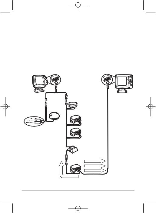
Accessory System Interconnects, Scenario 2
Fishing System
COM |
COM |
Accessory
GPS Receiver

 =
=


 =
=


 =
=


GPS Data
InterLink™
Accessory Data
Navigation Data
Fishing System
COM-ACCY
Smartcast™WSL
COM-ACCY
Accessory
WeatherSense®
COM-ACCY
COM-ACCY
GPS Data
Accessory Data
Navigation Data
6

531567-1_D - InterLink_Man.qxp 3/27/2007 3:57 PM Page 7
Accessory System Interconnects, Scenario 3
Fishing System |
Fishing System |
COM |
COM |
AS-YC ("Y") Cable
COM NMEA-COM
GPS Receiver
GPS Data
InterLink™
Accessory Data
Navigation Data
COM-ACCY
Smartcast™WSL
COM-ACCY
Accessory
Accessory
WeatherSense®
COM-ACCY
COM-ACCY
Navigation Data
7

531567-1_D - InterLink_Man.qxp 3/27/2007 3:57 PM Page 8
NOTE: If more than one GPS receiver is installed on the boat, the control heads interpreting the data from these GPS receivers may display slightly different locations due to the nature of GPS calculations.
4a. If the InterLink™ will stand alone on the mounting surface, use the four included M3x12 thread-forming screws to connect the two plastic feet to the bottom of the InterLink™, two screws for each foot.
Preparing the InterLink™ for Stand-Alone Mounting
Install the Plastic Feet
Plastic Foot
M3x12 

Screws
or...
4b. If you will be stacking the InterLink™ with another compatible Humminbird® accessory, use two of the included M3x12 threadforming screws to connect the two accessories, stacked one on top of the other. Proceed to Step 6.
8

531567-1_D - InterLink_Man.qxp 3/27/2007 3:57 PM Page 9
Preparing the InterLink™ for Stack Mounting
Stack Mounting Two Units
 M3x12
M3x12
Screw
M3x12
Screw
5.Use the installed plastic feet to mark and then drill the two 1/8” holes to a depth of 5/8" in the mounting surface, one for each foot, needed to attach the InterLink™ to the boat. Fill the holes in the mounting surface with marine-grade silicone sealant, then attach the InterLink™ to the mounting surface using the two included #8 x 5/8" wood screws.
NOTE: On fiberglass hulls, it is best to use progressively larger drill bits to reduce the chance of chipping or flaking the outer coating.
NOTE: Apply marine-grade silicone caulk or sealant to both screw and drilled holes as needed to protect your boat from water damage.
NOTE: If the mounting surface is thin or made of a light-weight material, you may need to add reinforcing material below the mounting surface in order to support the InterLink™.
6.When the control head detects the InterLink™, the InterLink™ menu items will be added automatically to the Menu system. This includes an InterLink™ Setup Dialog Box which appears when you power up either control head. See How the InterLink™ Affects the Control Head User Interface for more information.
9
 Loading...