


531568-1_B - CannonLink_Manual.qxp 12/28/2006 12:15 PM Page 1
CannonLink™
Downrigger Controller
531568-1_B
531568-1_B - CannonLink_Manual.qxp 12/28/2006 12:15 PM Page 2
Thank You!
Thank you for choosing Humminbird®, America's #1 name in fishfinders. Humminbird® has built its reputation by designing and manufacturing topquality, thoroughly reliable marine equipment. Your Humminbird® accessory is designed for trouble-free use in even the harshest marine environment. In the unlikely event that your Humminbird® accessory does require repairs, we offer an exclusive Service Policy - free of charge during the first year after purchase, and available at a reasonable rate after the one-year period. For complete details, see the warranty included in this manual. We encourage you to read this operations manual carefully in order to get full benefit from all the features and applications of your Humminbird® product.
Contact our Customer Resource Center at either 1-800-633-1468 or visit our website at www.humminbird.com.
WARNING! This device should not be used as a navigational aid to prevent collision, grounding, boat damage, or personal injury. When the boat is moving, water depth may change too quickly to allow time for you to react. Always operate the boat at very slow speeds if you suspect shallow water or submerged objects.
WARNING! Disassembly and repair of this electronic unit should only be performed by authorized service personnel. Any modification of the serial number or attempt to repair the originalequipmentoraccessoriesbyunauthorizedindividualswillvoidthewarranty. Handling and/or opening this unit may result in exposure to lead, in the form of solder.
WARNING! This product contains lead, a chemical known to the state of California to cause cancer, birth defects and other reproductive harm.
NOTE: If you have a chartplotter, the Downrigger View will not show sonar or depth. Caution shouldbeexercisedwhentheCannonLink™DownriggerControllerisusedinconjunctionwith a chartplotter. It is the user's responsibility to be aware of the operational depth as the chartplotter does not report back depth as a traditional fishfinder will.
NOTE: Fishfinder may require a software upgrade to be compatible with Cannonlink™ accessory. See www.humminbird.com for more information.
Humminbird®, Cannon™, CannonLink™, HumminbirdPCTM, X-Press™ Menu, SmartCast® and WeatherSense® are trademarked by or registered trademarks of Humminbird®.
© 2006 Humminbird®, Eufaula AL, USA. All rights reserved.

531568-1_B - CannonLink_Manual.qxp 12/28/2006 12:15 PM Page i
Table of Contents |
|
How Downriggers Work |
1 |
Positive Ion Control (PIC) .............................................................................................................. |
2 |
Downrigging Tips .......................................................................................................................... |
2 |
CannonLink™ Downrigger Controller Installation Overview |
4 |
CannonLink™ Downrigger Controller Connection Kit |
5 |
Connecting Your CannonLink™ to the Control Head and to the Downrigger(s) |
5 |
Setting Up Your Boat's Electrical Condition for Positive Ion Control |
11 |
Downrigger View |
12 |
The Menu System |
22 |
Start-Up Options Menu |
24 |
Normal Operation |
24 |
Simulator |
25 |
System Status |
26 |
Self Test |
26 |
Accessory Test |
27 |
GPS Diagnostic View |
27 |
PC Connect (with PC Connect Cable only) |
28 |
Setting Up Your Downriggers |
29 |
Linking the Downriggers |
31 |
Lowering (Activating) the Downriggers |
34 |
Making Changes |
35 |
Raising (Parking) the Downriggers |
36 |
i

531568-1_B - CannonLink_Manual.qxp 12/28/2006 12:15 PM Page ii
Table of Contents |
|
Downrigger X-Press™ Menu (Downrigger View only) |
38 |
Downrigger Setup........................................................................................................................ |
39 |
Activate All .................................................................................................................................. |
39 |
Park All.......................................................................................................................................... |
40 |
Activate Single ............................................................................................................................ |
40 |
Park Single.................................................................................................................................... |
41 |
Upper Range (Chartplotters only).................................................................................................. |
41 |
Lower Range (Chartplotters only).................................................................................................. |
42 |
Troubleshooting |
43 |
Fishing System Doesn’t Power Up.............................................................................................. |
43 |
Fishing System Defaults to Simulator with a Transducer Attached ........................................ |
43 |
Fuse Blows, Affecting Downriggers .......................................................................................... |
44 |
Control Head Doesn't Recognize Downriggers |
|
When a Downrigger is Attached................................................................................................ |
44 |
Temp-n-Speed Sensor Troubleshooting Tips.............................................................................. |
44 |
Display Problems.......................................................................................................................... |
45 |
Finding the Cause of Noise ........................................................................................................ |
46 |
Humminbird® Accessories |
47 |
Maintenance |
49 |
Humminbird® 1-Year Limited Warranty |
49 |
Humminbird® Service Policy |
50 |
Returning Your Unit For Service |
51 |
In-Warranty Service .................................................................................................................... |
51 |
Out-Of-Warranty Service ............................................................................................................ |
52 |
Notes |
53 |
Contact Humminbird® |
54 |
NOTE: Entries in this Table of Contents which list (with PC Connect Cable only) require the purchase of a separate accessory. You can visit our website at www.humminbird.com to order these accessories online or contact our Customer Resource Center at 1-800-633-1468.
ii
531568-1_B - CannonLink_Manual.qxp 12/28/2006 12:15 PM Page 1
How Downriggers Work
Downriggers allow you to catch fish you otherwise couldn’t even touch. By viewing sonar, temperature at depth and clarity information on screen while piloting the boat, you can monitor and position downriggers in real-time to the optimal depth to vastly increase the catch. Your Humminbird® CannonLink™ Downrigger Controller makes operation of up to six Cannon™ Mag 20 DT or Mag 20 DT/HS downriggers and one optional-purchase Cannon™ Speed-N-Temp Sensor incredibly easy.
•Automatically deploy or retrieve downriggers directly from any Fishing System.
•Set the downrigger operation mode to Manual for complete control, Bottom Track to maintain distance off the bottom or Cycle to continuously move the downriggers between two depths.
•Monitor the downrigger depth and operation graphically on-screen combined with the sonar graph.
•View temperature at depth, speed-through-water and water clarity on the Fishing System screen when using the optional-purchase Cannon™ Speed-N-Temp Sensor.
•Simultaneously or individually control up to 6 Cannon™ Mag20 DT and the Mag20 DT/HS downriggers.
NOTE: Your Humminbird® CannonLink™ Downrigger Controller only works with Cannon™ Mag 20 DT or Mag 20 DT/HS downriggers or the optional-purchase Cannon™ Speed-N-Temp Sensor. Although this manual discusses all three products, only the CannonLink™ Downrigger Controller is included with this manual.
Using the controls on your Fishing System, lower (activate) or raise (park) downriggers, hold your downrigger a specific distance from the bottom, move downriggers between two different depths, and adjust the Positive Ion Control to change the electrical charge emanating from your boat. You can even see temperature and water clarity (at depth and speed) at the downrigger ball on your control head screen when using the optional-purchase Cannon™ Speed-N-Temp. You’ll never be shorthanded again, since you can make adjustments from the helm, while your mate rigs the lines and brings in the fish!
1

531568-1_B - CannonLink_Manual.qxp 12/28/2006 12:15 PM Page 2
Positive Ion Control (PIC)
Positive Ion Control (PIC) is a feature of the CannonLink™ Downrigger Controller that allows you to use electricity to control this charge on your downriggers, so that it remains constant at a specified set positive voltage. It is important to prepare your boat's electrical condition before installing the CannonLink™ Downrigger Controller and downriggers to make sure that the Positive Ion Control feature will work most efficiently. The Positive Ion Control system applies a variable .2 to 1.2 Volts to the trolling cable at all times.
NOTE: All metal parts, including the hull (if metal), motor shaft outdrives, and thru-hull fittings, must be connected together using a bonding wire. The zinc anodes placed on your hull, propeller and other parts of your boat protect functioning metal parts from the natural corrosion that occurs when metals of different types that are physically or electrically connected are immersed in seawater. If your boat and zincs are set up correctly, the voltage on the stainless steel downrigger wire of your downrigger(s) should be positive when submerged.
Downrigging Tips
Try the cycle mode on the CannonLink™ Downrigger Controller to create a unique "action" in your lure. Many times this will trigger a strike.
When you have your downrigger set at the depth you want it, don't forget to set your clutch correctly. It is designed to "slip" in case your weight hangs up in rocks. This will avoid breaking the line and losing expensive lures or weights.
It's always a good idea to carry extra releases, weights, terminator kits and replacement cable in the boat. That way if you break or lose something while fishing, you can simply re-rig and not spend time out of the water.
Always keep your boat in gear when setting your downriggers. Allow the weight to descend slowly to avoid tangles. To be sure your lure is working properly, check its action at trolling speed.
If you notice that you're marking bottom-hugging fish, such as walleye or lake trout, try using the Humminbird® CannonLink™ Downrigger Controller exclusive bottom tracking feature.
2
531568-1_B - CannonLink_Manual.qxp 12/28/2006 12:15 PM Page 3
Your Humminbird® CannonLink™ Downrigger Controller allows you to control up to six Cannon™ Mag 20 DT or Mag 20 DT/HS downriggers easily, as well as one optional-purchase Cannon™ Speed-N-Temp Sensor, using your Humminbird® control head. The following functionality is supported by your Humminbird® control head when it is connected to the CannonLink™ Downrigger Controller:
•Vary the strength and type of electrical charge of the boat using Positive Ion Control (PIC);
•Setup each downrigger attached to your control head, and then change the settings during use;
•View settings for all downriggers connected to your control head at one time;
•Activate each downrigger separately, or all downriggers at once;
•Pull all downriggers up at the same time, or individually.
3

531568-1_B - CannonLink_Manual.qxp 12/28/2006 12:15 PM Page 4
CannonLink™ Downrigger Controller Installation Overview
Before installing your CannonLink™ Downrigger Controller, you should set up your boat for Positive Ion Control. You will then connect your CannonLink™ Downrigger Controller to your Humminbird® fishing system control head and up to 6 CannonLink™ downriggers (plus one optional-purchase Cannon™ Speed-N-Temp). You may also connect the CannonLink™ Downrigger Controller as part of a daisy chain of other Humminbird® accessories, by using the included daisy chain cable.
NOTE: The CannonLink™ Downrigger Controller will only support up to 6 CannonLink™ downriggers plus one optional-purchase Cannon™ Speed-N-Temp Sensor. Do NOT connect more than one optional-purchase Cannon™ Speed-N-Temp Sensor, as more than one may result in system instability.
NOTE: Only attach two downriggers to one battery. Humminbird® recommends that the downriggers have their own separate battery, and NOT be powered off the battery used to start the main gasoline engine of the boat. Confirm that all batteries are fully charged prior to each use.
NOTE: Installation of the terminator plug and proper grounding are both essential for proper operation. Confirm that each downrigger's NEG terminal is connected to the NEG terminal(s) of the boat's main/engine battery(ies).
NOTE: In the event that the downriggers lose power during operation, you must manually park the downriggers. You must also re-start the Humminbird(r) control head before you can resume normal operation.
NOTE: Confirm that all power connectors are securely fastened to the batteries and that all communications cables are securely fastened prior to each use.
4

531568-1_B - CannonLink_Manual.qxp 12/28/2006 12:15 PM Page 5
CannonLink™ Downrigger Controller Connection Kit
The Humminbird® CannonLink™ Downrigger Controller Connection Kit includes the following items:
•CannonLink™ Downrigger Controller
•One cable for multiple accessory attachment
•One control head connector cable
•One downrigger connector cable
•Terminator plug
•Hardware kit for stand-alone or stack mounting
•CannonLink™ Downrigger Controller Accessory Manual
NOTE: 10 foot extension cables are available as optional-purchase items. These can be used to extend the total cable length up to 50 feet.
Connecting Your CannonLink™ to the
Control Head and to the Downrigger(s)
Perform the following procedure to connect your CannonLink™ Downrigger Controller to your Humminbird® fishing system control head and up to 6 CannonLink™ downriggers (plus one optional-purchase Cannon™ Speed-N-Temp). You may also connect the CannonLink™ Downrigger Controller as part of a daisy chain of other Humminbird® accessories, by using the included daisy chain cable.
Perform the following installation procedure for your CannonLink™ Downrigger Controller Accessory:
1.Lay out the cables and the CannonLink™ Downrigger Controller to make sure that the cables will reach both the control head and all the downriggers that will be part of the daisy chain.
5

531568-1_B - CannonLink_Manual.qxp 12/28/2006 12:15 PM Page 6
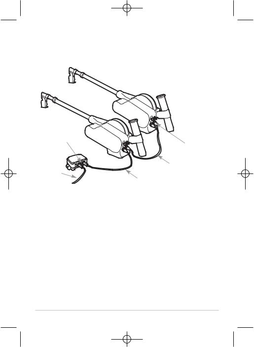
2.Interconnect the "To Control Head" connector either directly to the COM port on the control head or to the "Daisy Chain" connector of an accessory which is already attached to the control head. See the
Accessory System Interconnects diagram for more information.
CannonLink™ Downrigger Controller Ports

 To Downriggers
To Daisy Chain
To Control Head
NOTE: 10’ extension cables may be purchased from Humminbird® if your planned cable route exceeds 20’ (6 m). Maximum cable length, including extension cables, should not exceed 50’ (16 m). Visit our website at www.humminbird.com, or call our Customer Resource Center at 1-800-633-1468 to purchase extension cables.
3.Interconnect the "To Daisy Chain" connector to any other accessories which are in line after the Cannonlink™ accessory. See the Accessory System Interconnects diagram for more information.
4.Interconnect the "To Downriggers" connector to the first downrigger in the series. See the Accessory System Interconnects diagram for more information.
6
531568-1_B - CannonLink_Manual.qxp 12/28/2006 12:15 PM Page 7
Accessory System Interconnects
Fishing System

 =
=


 =
=


 = WHITE
COM NMEA-COM
COM
AS-YC ("Y") Cable
-COM |
Cannon |
TM |
Downrigger |
ACCY |
|
||
|
SmartcastTM WSL |
|
|
COM-ACCY |
|
|
|
GPS Receiver
CannonLinkTM
|
Terminator |
Accessory |
Plug |
WeatherSense
ACCY-COM
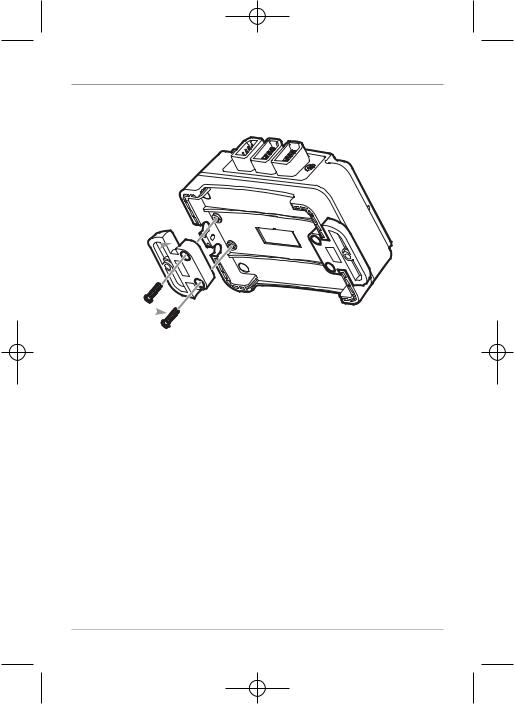
5a. If the CannonLink™ Downrigger Controller will stand alone on the mounting surface, use the four included M3x12 thread-forming screws to connect the two plastic feet to the bottom of the CannonLink™ Downrigger Controller, two screws for each foot.
or...
7
531568-1_B - CannonLink_Manual.qxp 12/28/2006 12:15 PM Page 8
Preparing the CannonLink™ for Stand-Alone Mounting
Install the Plastic Feet
Plastic Foot
M3x12
Screws
5b. If you will be stacking the CannonLink™ Downrigger Controller with another compatible Humminbird® accessory, use two of the included M3x12 thread-forming screws to connect the two accessories, stacked one on top of the other. Proceed to Step 7.
8

531568-1_B - CannonLink_Manual.qxp 12/28/2006 12:15 PM Page 9
Preparing the CannonLink™ for Stack Mounting
 M3x12
M3x12
Screw
M3x12
Screw
6.Use the installed plastic feet to mark and then drill the two 1/8” holes to a depth of 5/8" in the mounting surface, one for each foot, needed to attach the CannonLink™ Downrigger Controller to the boat. Fill the holes in the mounting surface with marine-grade silicone sealant, then attach the CannonLink™ to the mounting surface using the two included #8 x 5/8" wood screws.
NOTE: On fiberglass hulls, it is best to use progressively larger drill bits to reduce the chance of chipping or flaking the outer coating.
NOTE: Apply marine-grade silicone caulk or sealant to both screw and drilled holes as needed to protect your boat from water damage.
NOTE: If the mounting surface is thin or made of a light-weight material, you may need to add reinforcing material below the mounting surface in order to support the CannonLink™ Downrigger Controller.
7.Attach the terminator plug to the port on the last downrigger in the daisy chain that would normally be used to connect that downrigger to the next downrigger in the chain.
NOTE: The downriggers will not work without installing the terminator plug in the last downrigger in the daisy chain.
9
531568-1_B - CannonLink_Manual.qxp 12/28/2006 12:15 PM Page 10
NOTE: Downrigger daisy chain cables are not included with the CannonLink™ Downrigger Controller, but may be purchased from Cannon™. Visit the website at www.cannondownriggers.com, or call our Customer Resource Center at 1-800-227-6433 to purchase daisy chain cables.
To Additional |
Terminator |
Accessories |
Plug |
|
|
Downrigger Daisy |
|
To Control |
Chain Cable |
|
To Downrigger |
||
Head |
||
|
NOTE: Electric downriggers require a significant amount of power. It is recommended that you connect a maximum of 2 downriggers per battery.
8.When the control head detects the CannonLink™ Downrigger Controller, the Downrigger View will be added automatically to the VIEW key function, and the Downrigger X-Press™ menu will also be added automatically to the Menu system.
10

531568-1_B - CannonLink_Manual.qxp 12/28/2006 12:15 PM Page 11
Setting Up Your Boat's Electrical Condition for Positive Ion Control
Commercial fishermen know that fish, especially certain species, are attracted to positive charges and repelled by negative charges. The practice of setting up and maintaining a slight positive charge on fishing gear has been used by commercial fishermen for many years.
Your boat has an electrical charge around the hull where it is submerged, due to the interaction of weak electrical currents from various submerged pieces of equipment. These weak electrical currents must be controlled to extend the life of the boat's metal components and to provide a good fishing environment. If your boat is properly bonded and zinced, the charge should be slightly positive when measured from ground to the downrigger cable.
Positive Ion Control is a feature of the CannonLink™ Downrigger Controller that allows you to use electricity to control this charge on your downriggers, so that it remains constant at a specified set positive voltage. It is important to prepare your boat's electrical condition before installing the CannonLink™ Downrigger Controller and downriggers to make sure that the Positive Ion Control feature will work most efficiently. The Positive Ion Control system applies a variable .2 to 1.2 Volts to the trolling cable at all times.
NOTE: All metal parts, including the hull (if metal), motor shaft outdrives, and throughhull fittings, must be connected together using a bonding wire. If your boat and zincs are set up correctly, the voltage on the stainless steel downrigger wire of your downrigger(s) should be positive when submerged.
11
531568-1_B - CannonLink_Manual.qxp 12/28/2006 12:15 PM Page 12
Apply the following suggestions to help maintain a positive electrical charge:
•Use vinyl-coated lead weights, as uncoated lead, if not pure, can produce negative charges.
•Use the trolling weight insulators supplied with your downrigger(s) to insulate your weight from the positive charge on the cable. This also helps ensure that the trolling weight will stop at water level when retrieved.
•Replace the cable on your downrigger(s) every two years, since etching of the cable can weaken it physically and electrically.
•In salt water, replace the sacrificial zincs when they are half dissolved, to make sure that the boat will run with a neutral or slightly positive charge. Clean zincs on a regular basis with a non-abrasive brush.
•Make sure the boat is properly grounded to the water. This will help maintain proper Positive Ion Control voltage on the cable, and will make sure that the Short Stop feature will function properly.
NOTE: You must unplug the downrigger(s) before you can measure the natural voltage on the stainless steel cable accurately.
Downrigger View
The Downrigger View will be added to the View Rotation when a CannonLink™ Downrigger Controller is connected to the Fishing System:
The Downrigger View shows sonar information, plus information about any downrigger(s) that may be connected to your Fishing System. It displays the same Depth reading that all Humminbird® views display at the top left. It will also display speed/temp information if you have an optional-purchase Cannon™ Speed/Temp accessory attached to one of the downrigger cables. The bottom information box displays information about any downriggers you are controlling, as well as what mode (Manual, Cycle, or Bottom Track) they are in.
12

531568-1_B - CannonLink_Manual.qxp 12/28/2006 12:15 PM Page 13
NOTE: If you have a chartplotter, the Downrigger View will not show sonar or depth. Caution should be exercised when the CannonLink™ Downrigger Controller is used in conjunction with a chartplotter. It is the user's responsibility to be aware of the operational depth as the chartplotter does not report back depth as a traditional fishfinder will.
The icons on the right side of the screen represent the downriggers that you are controlling, where each icon represents a specific downrigger. You should have the same number of Downrigger Icons on the screen as you have downriggers. You will highlight a specific downrigger icon in order to see information about it displayed on the Downrigger View, and also to control that downrigger remotely.
NOTE: If the number of icons does not match the number of downriggers attached, check that the terminator plug is installed in the daisy chain port on the last downrigger in the daisy chain and that all of the cable connections in the daisy chain are firmly in place. Also check the connections on the power cables.
A gray bar highlights one or more of the downrigger icons. You can move this highlight by pressing the LEFT or RIGHT 4-Way Cursor keys. As you move the highlight bar, the numbers will change in the downrigger information box, indicating information about the downrigger you have currently highlighted.
You will access the Downrigger X-Press™ menu from the Downrigger View. You will be able to set up and link the downriggers, lower (activate) the downriggers, make changes to the downrigger settings, and raise (park) the downriggers using the X-Press™ menu. See Downrigger X-Press™ Menu for more information.
13

531568-1_B - CannonLink_Manual.qxp 12/28/2006 12:15 PM Page 14
Downrigger View, Bottom Track Mode, with
Depth |
|
Speed and Temp Information Box |
|
(only with optional-purchase |
|
Cannon™ Speed-N-Temp) |
|
Temp for Cannon™ |
|
Speed-N-Temp Sensor |
|
Water Speed for Cannon™ |
|
Speed-N-Temp Sensor |
|
Downrigger Information Box, |
|
showing Bottom Track Mode |
|
for Highlighted Downrigger 2 |
|
Offset: Distance of downrigger |
|
from bottom. Position of |
|
downrigger is changed to |
|
maintain a constant offset as |
|
the bottom terrain changes. |
|
Depth Lines |
|
NOTE: Use the LEFT and RIGHT 4-WAY Cursor Control keys to move the gray highlight bar between |
downrigger |
CannonLink™ Downrigger Controller. |
|
NOTE: The offset (constant distance maintained for the downrigger from the bottom) can be |
changed b |
updated on the screen and in the Downrigger Setup menu. |
|
14
 Loading...