


Overview
How the NS25 Works
Congratulations on your purchase of the Hummingbird NS25. The NS25 uses GPS and sonar capability to determine your position, display it on a map, and provide detailed underwater information.
The NS25 consists of four primary components; the control head, GPS receiver (SAT MAX), card reader and transducer. The control head contains the user controls and display. The GPS receiver receives signals transmitted by the constellation of GPS satellites orbiting the earth. It selects four or more satellites whose position and signal strength provide the most accurate position. From these four satellites, the GPS receiver calculates time, boat position (latitude/longitude), boat speed and direction of travel. The card reader displays electronic map information from the cartridges installed. The transducer is mounted beneath the water surface and converts electrical energy from the transmitter into mechanical pulses or sound waves. The transducer also receives the reflected sound waves and converts them back into digital signals for display on the sonar unit.
GPS
The Global Positioning System (GPS) is a satellite navigation system designed and maintained by the U.S. Department of Defense. GPS was originally intended for military use, however, civilians may also take advantage of its highly accurate position capabilities, typically within +/- 100 meters. This means that 95% of the time you will be within 300 feet of your actual position. Further capabilities are possible with the Differential Global Positioning Systems (DGPS), which operate to refine satellite signal to the most accurate position possible
GPS uses a constellation of 24 satellites that continually sends radio signals to the earth. Your position is determined by receiving signals from four or more satellites and measuring the distance from the satellites to determine your present position.
SONAR
Sonar uses sound waves to determine the presence and location of underwater objects. The time measured between the transmission of the sound wave and the reception of any reflection is used to determine distance. The transmit and receive cycle is very fast. A sound wave can travel
from the surface to a depth of 240 feet and back again in less than ¼ of a second, so it is unlikely that your boat can “outrun” this sonar signal. Analysis of the reflected signal can also be used to determine location, size, composition, etc.
NOTE: Actual depth capability depends on such factors as bottom hardness, water conditions, and transducer installation. Units will typically read deeper in fresh water than in salt water.
After spending a few minutes with your NS25 on the water, you will see the unit’s ability to accurately portray the underwater terrain, suspended targets, GPS position, and your position on a map.
Your NS25 comes with everything necessary for installation and operation on most boats. The transducer included, XT-6-20, is designed for mounting on the transom of the boat (directly exposed to the water). On fiberglass hull boats , this same transducer can be bonded to the inside of the hull. When mounted inside the hull, the sonar signal actually passes through the hll of the boat. Both mounting techniques produce acceptable results on most boats.
Installation
Parts Supplied
Before installing your NS25, please ensure that the following parts are included in the box:
∙Control Head
∙GPS Receiver
∙Transducer with 20 foot cable
∙Quick-Disconnect mounting hardware kit
∙Control head mounting hardware kit
∙GPS receiver mounting hardware kit
∙Card reader mounting kit
∙Transducer mounting hardware kit
∙6 foot power cable
∙20 foot GPS receiver extension cable
∙GPS “Y” cable for NMEA output and GPS receiver input
∙Publication kit
∙In-dash mounting kit
It is recommended that you install the NS25 components in the following order; 1) GPS receiver, 2) transducer, 3) card reader, then 4) control head.
GPS Receiver Installation
To optimize performance of the GPS receiver, mount it in an area that has full exposure to the sky. The effective area of reception is 10 degrees above the horizon.
Different circumstances determine the mounting method appropriate for your GPS receiver.
If you have… |
Then install: |
An existing antenna stem with |
Stem Mount |
Standard 1” – 14 thread |
(Existing Stem – Fig. A) |
Under location access with |
Deck Mount |
Deck less than 3/8” |
(Thin DeckFig. B) |
Under location access with |
Deck Mount |
Deck greater than 3/8” |
(Thick Deck – Fig C) |
No access under mounting |
Deck Mount |
Location |
(Cable Side – Fig. D) |
Note: When routing the GPS receiver extension cable, ensure the correct connector end is routed to the GPS receiver and control head.
An Existing Stern with 1” – 14 Thread
Follow these steps to stem mount the GPS receiver:
1.Determine best location, then route 20 foot cable to mounting location. Mark it and drill a ½” hole.
2.Place stem over ½” hole and mount with screws provided with stem.
3.Place lock nut on stem, thread down at least half way.
4.Route GPS receiver cable through stem. Continue through surface.
5.Thread GPS receiver on stem. Tighten lock nut with crescent wrench to secure GPS receiver head.
6.Connect extension cables to GPS receiver cable.
Under Location Access with Deck Less Than 3/8”
Follow these steps to deck mount the GPS receiver routing the cable down through the mounting surface:
1.Determine the best location, then route the 20 foot cable from control head to mounting location.
2.Mark mounting location and drill a 1” hole.
3.Insert mounting bolt through 1” hole from lower side of the mounting surface.
4.Place gasket over mounting bolt, route GPS receiver cable down through hole, then secure in place.
5.Connect extension cable to GPS receiver cable.
Under Location Access with Deck More Than 3/8”
Follow these steps to deck mount the GPS receiver routing the cable down through a thick deck:
1.Determine the best location, then route the 20 foot cable from control head to the mounting location.
2.Place mounting flange over mounting location and mark through holes for drilling. Center hole and three mounting holes.
3.Remove flange and drill a ½” hole and three 9/64” holes.
4.Assemble flange, bolt, and gasket, then place over ½” hole. Secure in place with #8 x 5/8 flat head screws.
5.Position the GPS receiver with cable through hole, then secure in place.
6.Connect extension cable to GPS receiver cable.
No Access Under Mounting Location GPS receiver routing the cable to the side.
1.Determine the best location, then route the 20 foot extension cable from control head to mounting location.
2.Place flange over mounting location and mark through the three mounting holes for drilling.
3.Remove flange and drill holes using a 9/64” drill bit.
4.Break out the marked tab on the bottom side, outer rim of the flange.
5.Preassemble the flange, mounting bolt, and gasket with the GPS receiver, routing cable through all components; tighten GPS receiver until its base is in contact with the gasket.
6.Secure flange with #8 x 5/8 flat head screws. To access all screws you will need to rotate the GPS receiver. When finished, secure tightly.
7.Determine a hole location where access for cable routing is available.
8.Drill a ½” hole at this location and route the cable through the hole.
9.Install escutcheon plate at this location with #8 x 5/8 flat head screws.
INSTALLATION PREPARATION
PARTS SUPPLIED
PARTS SUPPLIED
Before installing your new Humminbird fishfinder, please ensure the following parts are included in the box:
∙Fishfinder
∙Transducer with 20’ (6m) of cable and mounting hardware kit
∙Mounting system and mounting hardware kit
∙6’ (2m) power cable
∙Publications kit
It any of these items is missing, call our Customer Support Hotline.
ACCESSORIES
Humminbird offers a wide assortment of accessories that complement and expand the capability of your new fishfinder. These accessories are designed with the same high standards and are backed by the same one-year warranty. The Humminbird Accessory catalog included with your unit contains descriptions of the many accessories available and ordering information. All Humminbird accessories are available through your full-service Humminbird dealer or factory direct through our number listed in the Customer Support section.
INSTALLATION OVERVIEW
Your Humminbird fishfinder consists of two primary components to install: the control head and the transducer.
The control head contains the sonar transmit and receive circuitry, as well as the user controls and display. It should be installed in a location that provides access to the controls and visibility while in use. The control head mounts on a quick disconnect mounting system that swivels and tilts providing flexibility for viewing from almost anywhere on the boat.
The transducer converts electrical energy from the transmitter into mechanical pulses or sound waves. The transducer also receives the reflected sound waves and converts them back into electrical signals for display on the control head. It should be installed in contact with the surface of the water in an area that has smooth waterflowusually on the transom of the boat. There are several mounting options for the transducer. Review the following section to determine the method that works for you and your boat.

INSTALLATION PREPARATION
INSTALLATION OVERVIEW
Determining How to Mount the Transducer
Your Humminbird fishfinder includes a standard transducer. This transducer can be mounted on the transom of the boat or bonded to the inside of a fiberglass hull boat.
The transom installation, which is the most widely used, places the transducer on the outside of the boat hull. This technique produces the least signal loss, and provides a way to adjust the transducer after installation. The mounting hardware included is designed to protect both the boat and the transducer should the boat strike debris in the water or when trailering.
As an alternative to transom mounting, it is possible on many fiberglass-hulled boats to glue the transducer on the inside of the boat hull. Since fiberglass has similar sonar characteristics as water, the sonar signal can pass through the boat hull with minimal loss. The hull of the boat must be single layer construction (not double-hulled) Also, any air trapped in the lamination of the fiberglass would prevent the sonar signal from passing through.
Inside the hull installations require no holes be drilled into the boat and through experimentation, high-speed
operation comparable to transom mounting can be achieved. Two-part slow cure epoxy (not included) is required to glue the transducer in place.
INSTALLATION PREPARATION
ALTERNATE MOUNTING METHODS
ALTERNATE TRANSDUCERS AND MOUNTING METHODS
Your Humminbird fishfinder comes with everything necessary for installation and operation on most boats. However, there are several situations which may require a different type of transducer. Inboard boats, wood or metal hulls, and sail boats create unique transducer mounting needs Alternate transducers and mounting methods are detailed below.
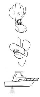
Portable Mounting
The standard transducer can be adapted for portable installations with a portable mounting kit available from Humminbird. This accessory adapts your transducer to a suction cup mount for temporary installation on the boat hull or other surface.
Trolling Motor Mounting
The standard transducer can also be adapted to mount on most trolling motors using a different accessory kit. This accessory includes a bracket and hose clamp that allows mounting the transducer to the body of most trolling motors.
Thru-Hull Mounting
Thru-hull transducers install through a hole drilled in the hull
of the boat. Larger boats or boats with inboard motors create turbulence that make transom mounting ineffective. Also, hulls that are very thick or are double layered, or made from materials such as wood or metal, (which do not conduct sonar signals) make inside the hull mounting inadvisable.
Thru-hull mounting may require the use of a fairing block to level the transducer with the waterline. Also, since special tools and knowledge may be required to perform this type of installation, it is best to refer to a qualified marine technician.
INSTALLATION PREPARATION
TRANSDUCER EXCHANGE
TRANSDUCER EXCHANGE
Other transducers are available as replacements for the standard transducer. You may exchange your new and unassembled transducer for another type by returning it to the address listed in Customer Support. Some transducers may have additional cost. Refer to the Accessory catalog or call Customer Support for information.
BEGINNING INSTALLATION
Now that you have determined the transducer mounting method you can begin installation of your new Humminbird fishfinder. The installation guide included on the next few pages provides detailed step by step instructions for installation of the control head and transducer. For transom mount transducer installations you will need the mounting template included with your manual.
In addition to the parts included you need the following for installation and operation:
∙A powered hand drill and various drill bits
∙Philips and flat-head screwdrivers
∙A ruler or measuring tape
∙Pen or pencil
∙12 volt power source (your boat’s battery)
∙A 1-amp fuse
∙A fuse holder (if you are wiring directly to the boat’s battery)
∙Silicone sealant (for sealing drilled holes)
∙2-part, slow-cure epoxy (for inside the hull transducer installations)

INSTALLATION
TRANSOM INSTALLATION
Do not begin this transducer installation until you read the Installation Preparation in the Operation Guide. This chapter contains information critical to the correct installation of your transducer.
Due to the wide variety of boat hulls, only general instructions are presented in the installation guide. Each boat hull represents a unique set of requirements that should be evaluated prior to installation.
TRANSOM INSTALLATION
Step One - Determine Where to Mount the Transducer
Begin the transducer installation by determining where on the transom to install the transducer. Consider the following to find the best location:
∙It is very important to locate the transducer in an area which is relatively free of turbulent water, As a boat moves through the water, turbulence is generated by the weight of the boat, and the thrust of the propeller(s). This turbulent water is normally confined to areas immediately aft of ribs, strakes or rows of rivets on the bottom of the boat, and in the immediate area of the propeller(s) (Figure 1). On outboard or inboard/outboard boats it is best to stay at least 15” (40cm) to the side of the propeller(s).
∙If possible, viewing the transom of the boat while the boat is moving will provide the best means of locating turbulence free water. If maximum high-speed operation is a high priority, this is the recommended method. If this is not possible, select a location on the transom where the hull forward of this location is smooth, flat, and free of protrusions or ribs.
∙The transducer when mounted should point straight down. The design of the transducer will accommodate a wide range of deadrises and remain ported straight down (Figure 2).
∙On boats with stepped hulls, it may be possible to mount the transducer on the step. Never mount the transducer on the transom behind a step, as this area of the transom will not be in contact with the water at high speed (Figure 3).
INSTALLATION
TRANSOM INSTALLATION
∙If the propeller(s) is (are) forward of the transom, it may be impossible to find an area clear from turbulence, and a different mounting technique or transducer type should be considered.
Step Two - Drill the Mounting Holes
1.Remove the mounting template from the front of the Operations Manual.
2.Hold the template on the transom of the boat in the location where the transducer will be installed (Figure 4). Align the template vertically, ensuring the lower edge of the transom meets with the bottom corner
of the template.
3.Using a pencil or punch, mark the two mounting holes shown on the template onto the transom. Do not mark or drill any other holes at this time.
4.Using a 5/32” (4mm) bit drill the two holes to a depth of approximately 1" (3cm). On fiberglass hulls, it is best to start with a smaller bit and use progressively larger drill bits to reduce the chance of chipping or flaking the outer coating.
Step Three - Assemble the Transducer
1.Attach the Pivot to the transducer body as shown in Figure 5, using the #8 – 3/8” (9mm) long allen headed pivot screw, the headed pin, the two flat washers, and the two toothed lock washers.
Note: The toothed lock washers must be positioned between the transducer and the pivot ears. The flat washers must be positioned to the outside at the pivot ears.
2.Using the AIlen wrenches provided, loosely tighten the pivot screw (Figure 6). Do not completely tighten the assembly at this time, so the pivot angle can be adjusted later.
3.Insert the pivot/transducer assembly into the mounting bracket as shown in Figure 7. Do not snap the assembly closed.

INSTALLATION
TRANSOM INSTALLATION
Step Four - Mount the Transducer to the Transom
1.Apply silicone sealant to the mounting holes drilled into the transom.
2.Align the transducer assembly with the drilled holes in the transom (Figure 8).
3.Use either a flat head screwdriver, a 5/16" (8mm) hex driver, or a 5/16" (8mm) socket to mount the assembly. Using the two #10 – 1”
(25mm) long slotted hex head screws, mount the transducer assembly to the transom as shown. Do not fully tighten the mounting screws in order to vertically adjust the transducer. Snap the pivot down into place.
Step Five - Adjust the Running Position of the Transducer
The bracket allows height and tilt adjustment, the pivot screws allow angular adjustment. Initially, adjust the transducer as described in the following paragraphs. Further adjustment may be necessary to refine the instillation after high speed testing.
1.First adjust the pivot angle of the transducer body so its length is parallel with the length of hull of the boat. Then pivot the transducer down so the rear is about 1/4 inch (6mm) lower than the front (Figure 9).
2.Fully tighten the two pivot screws using the Allen wrenches. It may be necessary to retighten the pivot screws after the initial use as the plastics may still be seating to the lock washers.
3.Adjust the height of the assembly so the face of the transducer is 3/16" (4.5mm) beneath the lower edge of the transom (Figure 10). Mark the position of the mounting bracket on the transom with a pencil.
4.Force the pivot to the up position to gain access to the mounting screws. Assure the transducer location has not changed, then fully tighten the two mounting screws (Figure 11). Snap the pivot back down.
Confirm the pivot angle has not changed.
Note: A third screw location is provided for the
mounting bracket. Drill this hole and install the screw after final testing and adjustments have been completed.
INSTALLATION
TRANSOM INSTALLATION
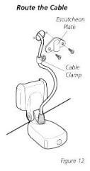
Step Six - Route the Cable
There are several ways to route the transducer cable to the to the area where the control head will be installed. The most common procedure routes the cable through the transom into the boat.
Inside the boat there is often a channel or conduit used for other wiring that the cable can be routed along. Do not cut or shorten the transducer cable and try not to damage the cable insulation. Route the cable as far as practical from the VHF radio antenna cables or tachometer cable to reduce the possibility of interference.
If the cable is too short, extension cables are available to extend the transducer cable up to a total of 50' (15 m). Call Humminbird Customer Support for more information.
Follow these steps to route the cable through the transom:
1.Drill a 5/8” (16mm) hole above the water line. Route the cable through the hole.
2.Fill the hole with silicone sealant.
3.Place the escutcheon plate over the hole and attach with the two #8 x 5/8” (16mm) screws.
4.Secure the cable by attaching the cable camp to the transom using a #8 x 5/8” (16mm) screw.
Note: The transducer will pivot up to 90 degrees in the bracket. Allow enough slack in the cable for this movement. It is best to route the cable to the side of the transducer so the cable will not be damaged by the transducer during movement.

INSTALLATION
INSIDE THE HULL INSTALLATION
INSIDE THE HULL INSTALLATION
Inside the hull installation requires the mount system and control head be installed and operational. See Installing the Control Head for instruction on installing the unit.
Inside the hull mounting generally produces good results in single thickness fiberglass-hulled boats. Humminbird cannot guarantee depth performance when transmitting and receiving through the hull of the boat since some signal loss occurs. The amount of loss depends on hull construction and thickness, and the installation.
This installation requires slow-cure two-part epoxy. Do not use silicone or any other soft adhesive to install the transducer, as this material reduces the sensitivity of the unit. Five minute epoxy has a tendency to cure before all the air bubbles can be purged.
Step One - Determine the Mounting Location
Begin the transducer installation by determining where inside the hull to install the transducer. Consider the following to find the best location:
∙Observe the outside of the boat hull to find the areas that are mostly free from turbulent water. Avoid ribs, strakes, and other protrusions as these create turbulence (Figure 14).
∙As a general rule, the faster the boat can travel the further aft and closer to the centerline of the hull the transducer has to be located to remain in contact with the water at high speeds.
Step Two - Test the Mounting Location
There is no opportunity for adjustment after the transducer glued
in place. Therefore, it is best to perform a trial installation on inside the hull transducers first, and run the boat at high speeds to determine the best mounting area.
1.At the identified mounting location, lay the transducer body face down with the pointed end towards the bow.
2.Fill the hull with enough water to submerge the transducer body. Use a sand filled bag or other heavy object to hold the transducer in position.
The transducer cannot transmit through air. The water purges any air from between the transducer and the hull and fills any voids in the coarse fiberglass surface.

INSTALLATION
INSIDE THE HULL INSTALLATION
3.Power up the Control Head.
4.Run the boat at various speeds and water depths while observing the screen on the Control Head. If the unit functions well at low speeds but begins to skip or miss the bottom at higher speeds, the transducer needs to be moved. If depth performance is required, test the fishfinder in water at the desired depth. Test different locations in the hull until the optimum performance is achieved.
Step Three - Permanently Mount the Transducer
1.Once the mounting location is determined, mark the position of the transducer.
2.Remove the water from inside the hull and thoroughly dry the mounting surface. If the surface is excessively rough, it may be necessary to sand the area to provide a smooth mounting surface.
Ensure the mounting area is clear and dry.
3.Mix an ample quantity of two-part slow-cure epoxy slowly and thoroughly. Avoid trapping air bubbles.
4.Coat the face of the transducer and the inside of the hull (Figure 16).
5.Press the transducer into place with a slight twisting motion to purge any trapped air from underneath, keeping the pointed end of the transducer body pointed forward (Figure 17).
Note: Proper operation requires the pointed end of the transducer body to face towards the bow.
6. Weight the transducer so it does not move while the epoxy is curing.
When the epoxy cures, no water is necessary inside the hull. Neither water, spilled gasoline, or oil will affect the performance of the transducer.

INSTALLATION
CONTROL HEAD INSTALLATION
CONTROL HEAD INSTALLATION
Step One - Determine Where to Mount
Begin the installation by determining where to mount the control head. Consider the following to determine best location:
∙The cables for power, transducer and temp/speed accessories (if applicable) should be installed first and must reach the mounting location. Extension cables are available.
∙There are two ways to route the cables to the unit: through a hole in the mounting surface underneath the mounting bracket or from a hole outside the mounting bracket. Routing the cables down under the mount provides maximum weather protection; however this is not always feasible if the area under the fishfinder is inaccessible. In this case, route the cables through a hole at another location and cover with the supplied hole cover.
∙The mounting surface should be adequately supported to protect the fishfinder from excessive wave shock and vibration, and provide visibility while in operation.
∙The mounting area should allow sufficient room for the unit to pivot and swivel freely, and for easy removal and installation (Figures 18-19).
Step Two - Connect the Power Cable to the Boat
A 6’ (2m) long power cable is included to supply power to the fishfinder. You may shorten or lengthen the cable using 18 gauge multi-stranded copper wire.
CAUTION: Some boats have 24 or 36 volt electric systems. Be sure your unit is connected to a 12 VDC power supply.
The Power can be connected to the boat's electrical system at two
places: a fuse panel, usually located near the console, or directly to the battery.
If a fuse terminal is available, use crimp-on type electrical connectors (not included) that match the terminal on the fuse panel. Attach the black wire to ground, and the red wire to 12 VDC power (Figure 20). Be sure to use a one amp
fuse in the connection. If you must wire the control head directly to a battery, be sure to install an inline fuse holder
INSTALLATION
CONTROL HEAD INSTALLATION
and one amp fuse (not included) for the protection of the unit (Figure 21). Humminbird is not responsible for over voltage or over current failures.
In order to minimize the potential for interference with other marine electronics a separate power source (such as a second battery) may be necessary.
Step Three - Drill the Mounting Holes
1.Set the mounting bracket in place on the mounting surface. Mark the four mounting screw locations with a pencil or punch.
2.Set the mounting bracket aside, and drill the four mounting screw holes using a 9/64” (3.6mm) bit.
Step Four - Run the Cables
1.If the cables must pass through a hole underneath the mounting surface, mark and drill a 1” (25mm) hole centered between the four mounting holes (Figure 22).
Note: if the cables must pass through the mounting surface at a different location, drill the 1" (25mm) hole at that location and pass the cables through from underneath. Also, you must break out the tabs on the rear of the mounting base using needle nose pliers (Figures 24-25).
2.Insert all cables through the 1” (25mm) hole from beneath the mounting surface.
3.Pass the cables through the grommet (if the cable hole is underneath the mounting bracket) then press the grommet in place around the cables and into the 1” (25mm) hole.
4.Pass the cables through the mounting base, out the top of the mounting bracket.
5.Place the mounting bracket on the mounting surface aligned with the drilled holes. Insert the four flathead wood screws into the mounting holes and tighten fully (Figure 23).
Optional: If the cables pass outside the mounting bracket, install the hole cover over the hole and fasten in place using the two #8 x 7/8” (22mm) wood screws (Figure 24).
 Loading...