


Before attempting to install or operate your Humminbird LCR, it is recommended that you read the operations manual thoroughly. The LCR is totally new concept in sonar and has a number of special features not found on any other recorder. To completely understand all the features of the LCR, we suggest you follow the instructions set forth in this manual. If, after reading the instructions, there is something you do not completely understand about the operations of your unit, we recommend you contact our Customer Service DepartmentCALL 334-687-0503.
IMPORTANT:
Complete your warranty card and return it to us immediately.
INTRODUCTION
Congratulations on selecting the most advanced piece of sonar equipment ever designed. Your new Humminbird LCR (Liquid Crystal Recorder) incorporates the most advanced, innovative
Concepts in sonar equipment. The LCR is probably the most intelligent depth sounder ever created. Advanced microcomputer technology is used to simplify its operation, not complicate it , so you can quickly learn the basics of operating your unit. After a couple of trips on the water, you will be operating your unit like an expert.
Your Humminbird LCR has a number of outstanding features including a unique automatic feature. This
Computer controlled feature makes using your LCR as simple as pushing the “On” button. The computer will automatically adjust the sensitivity, change the depth scale even if the bottom goes off the screen and black out everything below the bottom to make the display easy to read.
Other features include a High Visibility LCD readout, night light, low profile swivel movement, waterproof enclosure, four depth ranges beginning with a super-shallow 15 foot depth range, and more.
Read this operations manual thoroughly for all the outstanding features of your LCR. You will be amazed at its capabilities.
Since there are virtually no moving parts, your LCR will function more trouble free than any sonar unit you have ever owned.
This unit has been engineered, tested, manufactured and is guaranteed by the employee/owners of Humminbird, a division of Techsonic Industries, located on the shores of Lake Eufaula, Alabama.
Fishing, boating and depth sounders are our business, and at Humminbird we stand behind our products 100%.
Your new LCR is covered by our Lifetime Guaranteed Service policy. We wish you good luck, good fishing and many hours of pleasure with your new Humminbird LCR.
THEORY OF OPERATION
Your Humminbird LCR works on the basic principal of sonar.
An electric signal is generated within the control head of the unit. When coupled to the to, this signal is converted to an ultrasonic signal and is transmitted toward the bottom. The speed of the ultrasonic signal traveling through the water is approximately 4800 feet per second.
The signal travels through the water until it strikes an object or the bottom. At this instant it is reflected back , picked up by the transducer, reconverted to an electronic signal and is recorded on the display of the LCR.
The reading at the far right hand position of the display illustrates that which is being passed over at that time. If you are familiar with a flasher unit, you might think of the information coming on the right side of the screen as the information that would be seen at one instant on a flasher. However, unlike a flasher, this information is not lost but is shifted or moved to the left as new information comes on. Therefore, the information is retained until it disappears from the left hand position of the display.
The display used on the LCR is a Liquid Crystal Display. The material in the display is a liquid that can be aligned such that it either “blocks” light or it lets light pass through. This “blocking” of light is what makes the black dots on the screen.
Since the LCR’s display depends on light passing through it to make the images, increasing the light source will make it easier to use. This is why your LCR can be seen so well in direct sunlight. You will also notice that the display can be seen better at certain angles. The LCR mounting has been designed for tilting and pivoting so that you can easily maintain a good angle for viewing. Another characteristic of an LCD display is that you may find that some polarized glasses might affect the view by causing a rainbow prism to appear. This condition can possibly be improved by a slight adjustment in tilt.
The high visibility readout of the LCR allows you to see fish, bottom contour and underwater structure.
The LCR is designed to operate with a standard 16-degree transducer included with the unit. Other transducers, such as 32 degrees, cannot be used. In order for your LCR to operate well at high speeds, you must have a properly mounted transducer. Please read the transducer mounting procedure carefully.
TRANSDUCER MOUNTING PROCEDURE
Humminbird’s high-speed transducer is supplied with your LCR. This transducer has been designed to give good high speed readings on most all boat designs, including aluminum.
Please carefully consider the following before installing your transducer.

TRANSDUCER MOUNTING OPTIONS
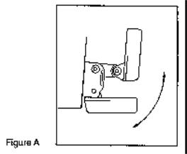
A.Transom MountThe Humminbird high speed transducer allows the transducer element to be mounted below the bottom of the boat hull keeping the transducer out of turbulent water and insuring good high speed operation. The transducer will absorb the blow of any obstruction by rotating up out of the metal spring bracket without harming the transducer, or your boat. The transducer can be re-engaged by simply rotating the transducer down and snapping it back in place. (See Figure A)
B.Inside Hull MountThe high speed transducer can be mounted inside the hull (without pivot assembly) using the proper two-part epoxy, such as Humminbird’s epoxy kit. Even though there is some loss of signal in shooting through the hull, your LCR will perform well with this type of installation. You cannot shoot through the hull of an aluminum boat.
C.Trolling motor MountThis type of transducer is not supplied with your LCR. It is designed to mount on the foot of a trolling motor. You may exchange your un-used high speed transducer for a trolling motor transducer. Call the Humminbird Customer Service Department.
D.Bronz Thru-Hull MountThis transducer is not supplied with your LCR but for an additional cost you may exchange your un-used high speed transducer for a bronz thru-hull. The bronz thru-hull transducer has a threaded stem which installs through a hole drilled in the boat hull, leaving the housing exposed under the boat. This type of installation must be used for many boats with inboard engines, because there is no suitable location on the transom away from the noise and turbulence created by the prop. A bronz thru-hull transducer should be installed by qualified personnel only.
The LCR will operate well at high speeds with a properly mounted transducer. Remember, a transducer will not work transmitting through air or through air bubbles.
1.TRANSOM MOUNTING PROCEEDURE
Step 1.
MOUNTING LOCATIONIt is important that the transducer be mounted on the transom where water flow is in constant contact with the transducer. You may wish to observe the rear of the boat while it is moving through the water to determine the best mounting location.
Step 2.
BRACKET INSTALLATION (Aluminum Boats)- To install the metal bracket on an aluminum boat locate the template on the transom between rows of rivets, or ribs that are on the bottom of the boat. Align the template so that the bottom corner of the template nearest the center of the transom is on the bottom edge of the transom.

Once the location is determined mark and drill three 7/64” dia.. holes noted on the template. Attach the metal bracket using three #10 self threading screws supplied. Be sure to align holes in the center of the Bracket slots. On some aluminum boats it may be necessary to use a wood back-up plate. It is important to use a silicone sealant between the screwhead and bracket in order to prevent leaking. (See Figure C)
Step 2.
BRACKET INSTALLATION (Fiberglass Boats)- If your boat has a stepped transom located below and under the main transom, the compact transducer design allows mounting in this area. This mounting location is recommended for good reading at very high speeds. (See Figure D)
To install the metal bracket on a fiberglass boat, locate the template on the transom in the same manner as for an aluminum boat. (See Figure C)
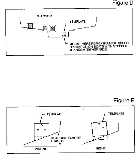
NOTE: On boats with more than 15 degree deadrise angle it may be necessary to mount the transducer slightly off parallel with the water level. (See Figure E)
Mark and drill the three 9/64” dia. holes as shown on the template. Attach the metal bracket using the three #10 self threading screws supplied. Be sure to align the holes so that they are centered vertically in the three slots found in the bracket. It is important to use a silicone sealant between the screwhead and bracket in order to prevent leaking.
Step 3.
TRANSDUCER PIVOT ASSEMBLYAssemble the pivot to the transducer main body using the two ¼”x5/8” allen head screws, two 3/8” tooth washers and two, ¼” square nuts. Make sure the tooth washers are sandwiched between the transducer main body and the pivot. The square nuts are trapped inside the pivot and will not rotate as the allen head screws are tightened. HOWEVER, DO NOT TIGHTEN AT THIS POINT. (See Figure F)

Step 4
TRANSDUCER ASSEMBLYInsert the transducer assembly into the metal bracket from the bottom. Push up until the holes in the plastic pivot align with the uppermost holes in the bracket. Slide the O- ring on to the headed pin and insert it through the two parts. Assemble by screwing the ¼”x3/8” allen head screw into the end of the pin and tighten. (See Figure G)
Step 5
ANGLE ALLIGHMENTSet the transducer angle so that it is parallel with the bottom of the boat hull. Once proper alignment is achieved, tighten the two allen head screws using the 5/32” allen wrench
 Loading...