


SOLIX
Operations Manual
532566-3EN_A

THANK YOU!
Thank you for choosing Humminbird®, the #1 name in marine electronics. Humminbird has built its reputation by designing and manufacturing top quality, thoroughly reliable marine equipment. Your Humminbird is designed for trouble-free use in even the harshest marine environment. In the unlikely event that your Humminbird does require repairs, we o er an exclusive Service Policy. For complete details, see the separate warranty card included with your unit. We encourage you to read this operations manual carefully in order to get the full benefit from all the features and applications of your Humminbird product.
Contact Humminbird Customer Service at humminbird.com or call 1-800-633-1468.
WARNING! This device should not be used as a navigational aid to prevent collision, grounding, boat damage, or personal injury. When the boat is moving, water depth may change too quickly to allow time for you to react. Always operate the boat at very slow speeds if you suspect shallow water or submerged objects.
WARNING! The electronic chart in your Humminbird unit is an aid to navigation designed to facilitate the use of authorized government charts, not to replace them. Only official government charts and notices to mariners contain all of the current information needed for the safety of navigation, and the captain is responsible for their prudent use.
WARNING! Compass Safe Distance: The control head must be installed at least 4 feet (1.2 meters) from the compass or other magnetic equipment on the boat. Also, see your compass installation guide for details.
WARNING! This device is granted for use in Mobile only configurations in which the antennas used for this transmitter must be installed to provide a separation distance of at least 8 inches (20 cm) from all person and not be co-located with any other transmitters except in accordance with FCC and Industry Canada multi-transmitter product procedures.
WARNING! Humminbird is not responsible for the loss of data files (waypoints, routes, tracks, groups, recordings, etc.) that may occur due to direct or indirect damage to the unit’s hardware or software. It is important to back up your control head’s data files periodically. Data files should also be saved to your PC before restoring the unit’s defaults or updating the software. Review the information in this manual for details.
WARNING! Disassembly and repair of this electronic unit should only be performed by authorized service personnel. Any modification of the serial number or attempt to repair the original equipment or accessories by unauthorized individuals will void the warranty.
WARNING! Do not travel at high speed with the unit cover installed. Remove the unit cover before traveling at speeds above 20 mph.
NOTE: Some features discussed in this manual require a separate purchase, and some features are only available on international models. Every effort has been made to clearly identify those features. Please read the manual carefully in order to understand the full capabilities of your model.
NOTE: The illustrations in this manual may not look the same as your product, but your unit will function in a similar way.
NOTE: To purchase accessories or any additional equipment for your control head configuration, visit our Web site at humminbird.com or contact Humminbird Customer Service at
1-800-633-1468.
NOTE: The procedures and features described in this manual are subject to change without notice. This manual was written in English and may have been translated to another language. Humminbird is not responsible for incorrect translations or discrepancies between documents.
NOTE: Product specifications and features are subject to change without notice.
NOTE: Humminbird verifies maximum stated depth in saltwater conditions, however actual depth performance may vary due to transducer installation, water type, thermal layers, bottom composition, and slope.
ROHS STATEMENT: Product designed and intended as a fixed installation or part of a system in a vessel may be considered beyond the scope of Directive 2002/95/EC of the European Parliament and of the Council of 27 January 2003 on the restriction of the use of certain hazardous substances in electrical and electronic equipment.
ATTENTION INTERNATIONAL CUSTOMERS: Products sold in the U.S. are not intended for use in the international market. Humminbird international units provide international features and are designed to meet country and regional regulations. Languages, maps, time zones, units of measurement, and warranty are examples of features that are customized for Humminbird international units purchased through our authorized international distributors.
To obtain a list of authorized international distributors, please visit our Web site at humminbird.com or contact Humminbird Customer Service at (334) 687-6613.
2

360 Imaging®, AUTOCHART®, AutoChart® LIVE, ChartSelect®, Cross Touch®, Down Imaging®, DualBeam PLUS™, Dual Spectrum™, Fish ID+™, FishSmart™, Humminbird®, Humminbird Basemap™, i-Pilot® Link™, LakeMaster®, MEGA Imaging™, MEGA Down Imaging™, MEGA Down Imaging+™, MEGA Side Imaging™, MEGA Side Imaging+™, Real Time Sonar™, RTS Window™, SI™, Side Imaging®, SmartStrike™, SOLIX®, Structure ID™, SwitchFire®, WhiteLine™, X-Press™ Menu, and ZeroLine Map Card™ are trademarked by or registered trademarks of Johnson Outdoors Marine Electronics, Inc.
Airmar is a registered trademark of Airmar Technology Corp.
Adobe, Acrobat, Adobe PDF, and Reader are either registered trademarks or trademarks of Adobe Systems Incorporated in the United States and/or other countries.
Baekmuk Batang, Baekmuk Dotum, Baekmuk Gulim, and Baekmuk Headline are registered trademarks owned by Kim Jeong-Hwan.
The Bluetooth® word mark and logos are registered trademarks owned by the Bluetooth SIG, Inc. and any use of such marks by Johnson Outdoors, Inc. is under license. Other trademarks and trade names are those of their respective owners.
Gentoo™ is a trademark of Gentoo Foundation, Inc.
microSD and SD are trademarks or registered trademarks of SD-3C, LLC in the United States, other countries or both.
Navionics® is a registered trademark of Navionics S.p.A.
NMEA 2000® is a registered trademark of the National Marine Electronics Association.
© 2019 Johnson Outdoors Marine Electronics, Inc. All rights reserved.
3

TABLE OF CONTENTS
Warnings |
2 |
Introduction |
6 |
Using Humminbird Manuals on your Mobile Device or Computer |
. .7 |
The SOLIX Control Head |
8 |
SOLIX Touch Screen and Keypad . . . . . . . . . . . . . . . . . . . . . . . . . . |
.9 |
SD Card Slots . . . . . . . . . . . . . . . . . . . . . . . . . . . . . . . . . . . . . . . . . . . |
14 |
Power On/Off |
15 |
Getting Started |
16 |
The Home Screen |
24 |
The Menu System |
32 |
Views |
38 |
Edit the On-Screen View . . . . . . . . . . . . . . . . . . . . . . . . . . . . . . . . .41 The View Options Menu . . . . . . . . . . . . . . . . . . . . . . . . . . . . . . . . . .50 Create a New View . . . . . . . . . . . . . . . . . . . . . . . . . . . . . . . . . . . . . . .53 Set up an Instrument View . . . . . . . . . . . . . . . . . . . . . . . . . . . . . . .57
Chart Overview |
59 |
Map Source Overview . . . . . . . . . . . . . . . . . . . . . . . . . . . . . . . . . . . .60
Navigation Alarms Overview . . . . . . . . . . . . . . . . . . . . . . . . . . . . . .70
Man Overboard (MOB) Navigation . . . . . . . . . . . . . . . . . . . . . . . . .74
Customize the Chart View . . . . . . . . . . . . . . . . . . . . . . . . . . . . . . . .75
Change the Chart View Data Overlays . . . . . . . . . . . . . . . . . . . . . .84
Chart and Radar . . . . . . . . . . . . . . . . . . . . . . . . . . . . . . . . . . . . . . . .85
Introduction to Navigation |
86 |
Navigation Menu Overview |
87 |
Navigation X-Press Menu . . . . . . . . . . . . . . . . . . . . . . . . . . . . . . . . .87
Mark Menu . . . . . . . . . . . . . . . . . . . . . . . . . . . . . . . . . . . . . . . . . . . . . .88
Go To Menu . . . . . . . . . . . . . . . . . . . . . . . . . . . . . . . . . . . . . . . . . . . . .88
Info Menu . . . . . . . . . . . . . . . . . . . . . . . . . . . . . . . . . . . . . . . . . . . . . . .90
Cursor Menu . . . . . . . . . . . . . . . . . . . . . . . . . . . . . . . . . . . . . . . . . . . .92
Waypoints |
93 |
Routes |
98 |
Search |
105 |
Tracks |
107 |
Manage your Navigation Data |
110 |
Manage Waypoints . . . . . . . . . . . . . . . . . . . . . . . . . . . . . . . . . . . . .111
Manage Routes . . . . . . . . . . . . . . . . . . . . . . . . . . . . . . . . . . . . . . . .114
Manage Tracks . . . . . . . . . . . . . . . . . . . . . . . . . . . . . . . . . . . . . . . . .116
Manage Groups . . . . . . . . . . . . . . . . . . . . . . . . . . . . . . . . . . . . . . . .119
Delete All Navigation Data . . . . . . . . . . . . . . . . . . . . . . . . . . . . . . .120
Import/Export Navigation Data . . . . . . . . . . . . . . . . . . . . . . . . . .120
AutoChart LIVE Overview |
121 |
Plan your Map . . . . . . . . . . . . . . . . . . . . . . . . . . . . . . . . . . . . . . . . . .121 Prepare the Control Head for Mapping . . . . . . . . . . . . . . . . . . . .122 Record your Custom Map . . . . . . . . . . . . . . . . . . . . . . . . . . . . . . .125 Stop Recording . . . . . . . . . . . . . . . . . . . . . . . . . . . . . . . . . . . . . . . .126 Correct Data . . . . . . . . . . . . . . . . . . . . . . . . . . . . . . . . . . . . . . . . . . .127 Display the AutoChart Live Map . . . . . . . . . . . . . . . . . . . . . . . . . .128 Adjust the Map Display Settings . . . . . . . . . . . . . . . . . . . . . . . . .130 Customize the Bottom Hardness Display Settings . . . . . . . . .134 Customize the Vegetation Display Settings . . . . . . . . . . . . . . .137
Mosaic Live Overview |
140 |
For Best Performance . . . . . . . . . . . . . . . . . . . . . . . . . . . . . . . . . .140
Open the Mosaic Live Menu . . . . . . . . . . . . . . . . . . . . . . . . . . . . .141
Customize the Mosaic Live Display . . . . . . . . . . . . . . . . . . . . . . .143
Autopilot Overview |
147 |
Radar Overview |
149 |
Radar Transmission Settings . . . . . . . . . . . . . . . . . . . . . . . . . . . .150
Adjust the Transmission Range . . . . . . . . . . . . . . . . . . . . . . . . . .153
Radar Alarms . . . . . . . . . . . . . . . . . . . . . . . . . . . . . . . . . . . . . . . . . .154
Customize the Radar View . . . . . . . . . . . . . . . . . . . . . . . . . . . . . .157
Open the Radar Preferences Menu . . . . . . . . . . . . . . . . . . . . . . .157
Change the Radar View Data Overlays . . . . . . . . . . . . . . . . . . . .159
Adjust Radar Signal Settings . . . . . . . . . . . . . . . . . . . . . . . . . . . .161
EBL/VRM . . . . . . . . . . . . . . . . . . . . . . . . . . . . . . . . . . . . . . . . . . . . . .164
Navigation in Radar View . . . . . . . . . . . . . . . . . . . . . . . . . . . . . . . .166
AIS and MARPA |
168 |
AIS and MARPA Alarms . . . . . . . . . . . . . . . . . . . . . . . . . . . . . . . . . |
.168 |
AIS and MARPA Display Settings . . . . . . . . . . . . . . . . . . . . . . . . . |
170 |
AIS Overview |
172 |
MARPA Targets |
179 |
4

TABLE OF CONTENTS |
|
Sonar Overview |
184 |
Sonar Setup . . . . . . . . . . . . . . . . . . . . . . . . . . . . . . . . . . . . . . . . . . |
.190 |
Sonar Alarms . . . . . . . . . . . . . . . . . . . . . . . . . . . . . . . . . . . . . . . . . . |
191 |
2D Sonar Overview |
192 |
Customize the 2D Sonar View . . . . . . . . . . . . . . . . . . . . . . . . . . .193 Open the 2D Sonar Preferences Menu . . . . . . . . . . . . . . . . . . . .193 Change the 2D Sonar View Overlays . . . . . . . . . . . . . . . . . . . . . .199 Adjust 2D Sonar Display Settings . . . . . . . . . . . . . . . . . . . . . . . .200
Side Imaging Overview |
205 |
Customize the Side Imaging View . . . . . . . . . . . . . . . . . . . . . . . .207 Open the Side Imaging Preferences Menu . . . . . . . . . . . . . . . .207 Change the Side Imaging View Overlays . . . . . . . . . . . . . . . . . .209 Adjust Side Imaging Display Settings . . . . . . . . . . . . . . . . . . . . .210
Down Imaging Overview |
213 |
Customize the Down Imaging View . . . . . . . . . . . . . . . . . . . . . . .214 Open the Down Imaging Preferences Menu . . . . . . . . . . . . . . .214 Change the Down Imaging View Overlays . . . . . . . . . . . . . . . . .216 Adjust Down Imaging Display Settings . . . . . . . . . . . . . . . . . . . .217
Use Cursor and Zoom in Sonar Views (2D, SI, DI) |
220 |
Navigation in Sonar Views (2D, SI, DI) |
222 |
Sonar Recording |
224 |
Images Tool |
225 |
Installation Information |
231 |
Set up or Change Transducer Settings (advanced settings) . . .232 Configure Humminbird Radar (Installation and Repair only) . .240 Configure the Control Head . . . . . . . . . . . . . . . . . . . . . . . . . . . . .243 Set up a NMEA 2000 Network . . . . . . . . . . . . . . . . . . . . . . . . . . .247 Set up your Humminbird Network . . . . . . . . . . . . . . . . . . . . . . . .256 Change the Network Name . . . . . . . . . . . . . . . . . . . . . . . . . . . . . .262
Manage your Control Head |
264 |
Update Software |
266 |
Specifications |
270 |
Statements and Acknowledgements |
282 |
Contact Humminbird |
288 |
5

INTRODUCTION
The instructions in this manual describe the SOLIX control head operations. For an overview of functions, see the Quick Start Guide included with your product.
Build your Network: Some of the features shown in this manual require a separate purchase. Radar, Talon, AIS, Compass/Heading Sensor, Ethernet Switch, i-Pilot Link, etc. require a separate purchase. To install each accessory, use the installation guide provided with it, or download the guide from our Web site at humminbird.com.
Register and Update: As you build your Humminbird network, it is important to register your products and keep your software up to date. Visit our Web site at humminbird.com to register your Humminbird products, update control head and accessory software, and purchase additional equipment. Also, see Update Software in this manual for more information.
Introduction |
6 |

USING HUMMINBIRD MANUALS ON YOUR MOBILE DEVICE OR COMPUTER
The Humminbird manuals for your control head and accessories can be downloaded to your mobile device or computer. If you prefer to use a hard copy for reference, this manual may be printed.
Download the Manual to your Mobile Device
1.Download the free Adobe Acrobat Reader app to your mobile device.
2.Go to our Web site at humminbird.com, and click Support > Manuals.
3.Select the PDF for your control head model or accessory, and save it to your device.
4.Open the Adobe Acrobat Reader app.
5.Open the Humminbird manual.
Download the Manual to your Computer
1.Download the free Adobe Acrobat Reader software from http://get.adobe.com/reader/, and install it on your computer.
2.Go to our Web site at humminbird.com, and click Support > Manuals.
3.Select the PDF for your control head model or accessory, and save it to your computer.
4.Open Adobe Acrobat Reader.
5.Open the Humminbird manual.
Jump to a Section: Click a section name in the Bookmarks panel. Bookmarks can be expanded and collapsed by clicking on the plus (+) or minus (-) icons.
Search for Words or Phrases: Press and hold the Ctrl F keys on your keyboard. Type the word(s) into the text box.
Print: To print, confirm the page sizing is 8.5 x 11" and set to Fit. Set the page orientation to Portrait.
Using the Manual
 search for bookmarks
 key words
panel
(Ctrl + F)
7 |
Introduction |
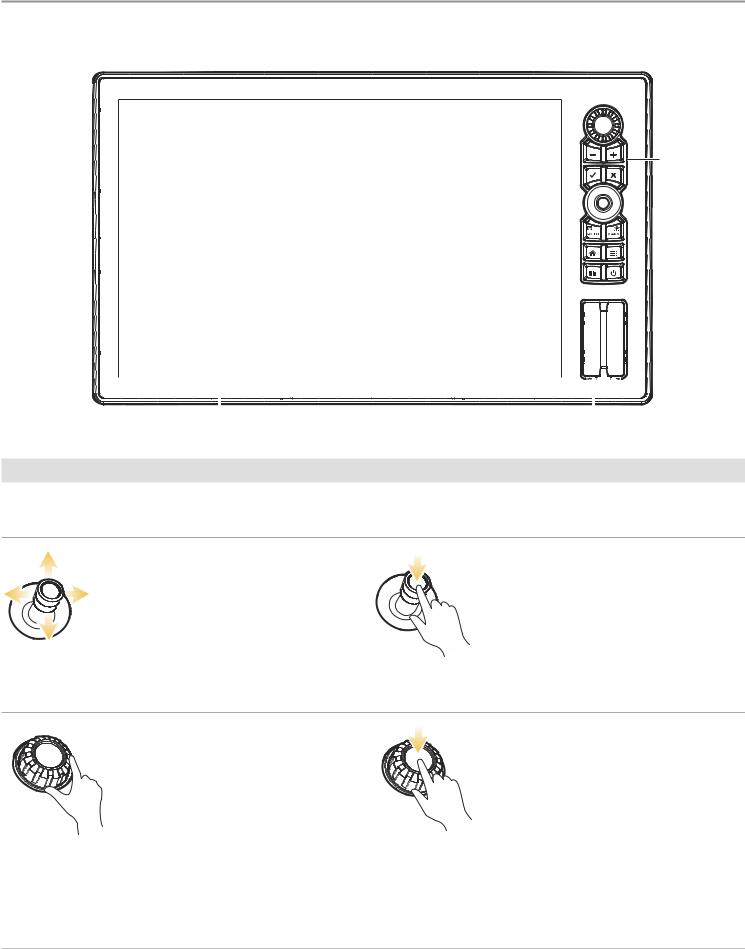
THE SOLIX CONTROL HEAD
The SOLIX control head includes CrossTouch, which allows you to use both the touch screen and keypad to make selections. Review this section for an overview of touch and keypad functions.
keypad
|
|
|
|
|
|
|
|
|
|
|
|
|
|
|
|
|
|
|
|
|
|
|
|
|
|
|
|
touch |
screen |
SD or microSD card slots |
|||||
Keypad Functions
The functions for each key are described here. To apply the key functions, see each section of this manual.
Joystick
Move Functions
Move to select a view, tool, widget, or menu.
Move to activate and/or move the cursor across the displayed view.
(Down) Press Functions
Open your selected view, tool, widget, menu, or submenu.
Mark a route point.
Rotary Dial
Turn Functions
Turn to adjust menu settings.
Turn to adjust the sensitivity in Sonar Views.
Turn to zoom in and out in Chart View.
Turn to adjust in Radar View.
(Down) Press Function
Press the Rotary dial to open the Favorite Views widget.
The SOLIX Control Head |
8 |
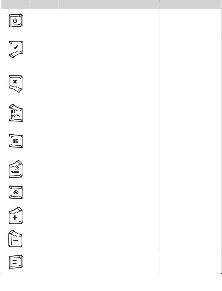
Key |
Name |
Key Press Function(s) |
Key Press Function(s) |
|
POWER key |
Powers on the control head. |
Powers off the control head. |
|
|
During operation, this key opens the Power X-Press Menu.
|
|
|
|
|
|
Starts a command. |
|
|
|
|
|
|
|
|
|
ENTER key |
Selects, or turns on, a setting. |
Adjusts menu settings. |
|
||
|
|
|
|
|
|
|||||
|
|
|
|
|
Opens menus. |
May vary with the displayed view. |
||||
|
|
|
|
|
|
|||||
|
|
|
|
|
|
Opens the Info menu and the Cursor menu. |
|
|
|
|
|
|
|
|
|
|
|
|
|
|
|
|
|
|
|
|
|
Closes an open menu or dialog box. |
|
|
|
|
|
|
|
|
|
EXIT key |
Turns o an alarm. |
Closes all open submenus and |
|||
|
|
|
|
|
||||||
|
|
|
|
|
|
|||||
|
|
|
|
|
Exits Cursor mode. |
menus. |
|
|
||
|
|
|
|
|
|
|
|
|||
|
|
|
|
|
|
Returns to the last displayed view from the Home screen. |
|
|
|
|
|
|
|
|
|
|
|
|
|
||
|
|
|
|
|
GO TO & |
Opens the Go To menu for navigation functions (see |
Screen Snapshot: Saves |
the |
||
|
|
|
|
|
||||||
|
|
|
|
|
Screen |
on-screen view |
(image). See |
|||
|
|
|
|
|
Routes for details). |
|||||
|
|
|
|
|
Snapshot key |
Images Tool. |
|
|
||
|
|
|
|
|
|
|
|
|||
|
|
|
|
|
|
|
|
|
|
|
|
|
|
|
|
|
|
|
|
|
|
|
|
|
|
|
|
Activates the Side Bar (the side bar is highlighted in |
|
|
|
|
|
|
|
|
|
|
yellow). Use the Joystick to scroll through the side bar |
|
|
|
|
|
|
|
|
|
PANE key |
widgets. |
|
|
|
|
|
|
|
|
|
|
|
|
|
|
|
|
|
|
|
|
|
Selects a pane in a multi-pane view (the selected pane |
|
|
|
|
|
|
|
|
|
|
|
|
|
|
|
|
|
|
|
|
|
|
|
|
|
|
|
|
|
|
|
|
is highlighted in yellow. See Views.) |
|
|
|
|
|
|
|
|
|
|
|
|
|
|
|
|
|
|
|
|
MARK & |
|
Man |
Overboard: |
Starts |
Man |
|
|
|
|
|
Man Overboard |
Press TWICE to mark waypoints. |
Overboard (MOB) Navigation. See |
|||
|
|
|
|
|
Man |
Overboard |
(MOB) |
and |
||
|
|
|
|
|
key |
|
||||
|
|
|
|
|
|
Introduction to Navigation). |
||||
|
|
|
|
|
|
|||||
|
|
|
|
|
|
|
||||
|
|
|
|
|
|
|
|
|
|
|
|
|
|
|
|
HOME key |
Displays the Home screen. See The Home Screen. |
|
|
|
|
|
|
|
|
|
|
|
|
|
||
|
|
|
|
|
|
|
|
|
|
|
|
|
|
|
|
|
|
|
|
|
|
|
|
|
|
|
|
|
|
|
|
|
|
|
|
|
|
ZOOM In key |
Changes the scale of the view to show a closer |
|
|
|
|
|
|
|
|
|
|
|
|
|
||
|
|
|
|
|
|
|
|
|
||
|
|
|
|
|
|
|
|
|
||
|
|
|
|
|
perspective. |
|
|
|
|
|
|
|
|
|
|
|
|
|
|
|
|
|
|
|
|
|
|
|
|
|
|
|
|
|
|
|
|
|
|
|
|
|
|
|
|
|
|
|
ZOOM Out key |
Changes the scale of the view to show a wider view. |
Zoom out all the way. |
|
||
|
|
|
|
|
|
|||||
|
|
|
|
|
|
|||||
|
|
|
|
|
|
|||||
|
|
|
|
|
|
|||||
|
|
|
|
|
|
|||||
|
|
|
|
|
|
|
|
|
|
|
|
|
|
|
|
|
|
|
|
|
|
Opens the X-Press Menu for the on-screen view and
MENU key operation mode. Returns to the last-used Settings tool tab. See The Menu System.
Press TWICE to open the Settings tool.
9 |
The SOLIX Control Head |
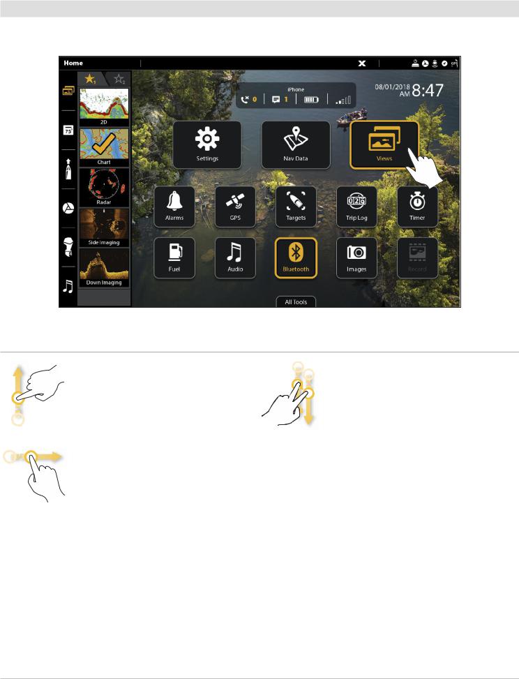
Touch Screen Functions
The touch screen actions are also determined by the view displayed on the screen.
Using the Touch Screen
Swipe Functions
One Finger Swipe (vertical)
Browse Menus: Scroll through a menu or list (up or down).
One Finger Swipe (horizontal)
Adjust Menu Slider: Drag the slider to adjust the setting.
With a Chart View displayed on the screen, drag one finger across the screen to see more of the chart that is displayed off-screen.
With a 2D Sonar View displayed on the screen, drag one finger across the screen to see more of the sonar history.
Two Finger Swipe
With a view displayed on-screen, touch the screen with two fingers and swipe down to return to the Home screen.
The SOLIX Control Head |
10 |
Tap Functions
One Tap |
Two Taps |
Select (Open): Tap to select (or open) a |
Tap the screen twice to zoom in on the |
view, tool, widget, menu, or icon. |
current display. |
Activate the Cursor: Tap a position on the |
|
view once. |
|
Press and Hold Functions
Pinch
Zoom In: Touch the screen with two fingers and move them apart to zoom in on the display.
Zoom Out: Touch the screen with two fingers and bring them closer together to zoom out.
Press and Hold
Press and hold a position on the view with one finger to open the Cursor Menu.
11 |
The SOLIX Control Head |

Basic Touch Screen and Keypad Operations
Select (Open) a Tool, Widget, or View
Touch Screen |
Keypad |
Select |
Open |
tap to open
Adjust a Menu Setting
Touch Screen |
|
Keypad |
||
|
|
|
|
|
|
|
|
|
|
|
|
|
|
|
|
|
|
|
|
|
|
|
|
|
|
|
|
|
|
Tap |
Press |
|
|
|
OR |
Press and Hold OR Slide |
Turn |
Press and Hold |
Close a Tool or Menu
Touch Screen Keypad
Select |
Close |
tap to close
The SOLIX Control Head |
12 |
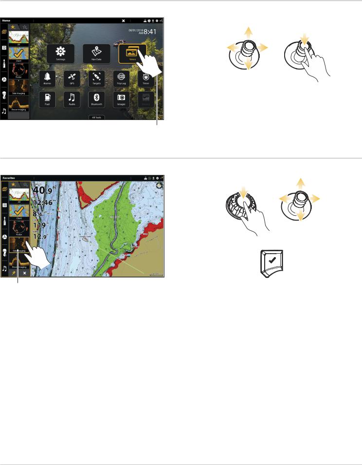
Open a View from the Views Tool
Touch Screen |
Keypad |
Select |
Display |
tap to open
Open a View from the Favorite Views Widget
Touch Screen |
Keypad |
Open |
Select |
tap to open |
Display |
13 |
The SOLIX Control Head |
SD Card Slots
Your control head may be compatible with an SD or microSD card (separate purchase required). Use it to update software, add detailed charts to your control head, import/export navigation data, and save sonar recordings and screen snapshots. Use the instructions in this section to install the card.
CAUTION! Before the control head software is updated or restored to system defaults, export your menu settings, radar settings, and navigation data (see Update Software).
WARNING! Do not leave the card slot cover open. The slot cover should always be closed to prevent water damage to the unit.
Insert an SD Card |
Load an SD Card |
The left slot is displayed as SD Card (1) in the menu system, and the right slot is displayed as
SD Card (2).
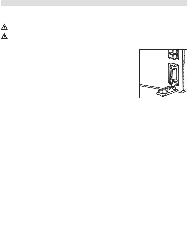
1. Remove the SD card slot cover.
2. Position the SD card so that the label faces to the left.
3. Insert the card into the slot until it clicks into place.
4. Replace the slot cover so it is secure.
5. Remove: Press the card into the slot and then release it. The card will eject. Pull the card carefully from the slot.
Insert the SD card with the label facing left
Insert a microSD Card
The top slot is displayed as SD Card (1) in the menu system, and the bottom slot is displayed as SD Card (2).
1.Remove the microSD card slot cover.
2.Remove the microSD card from the microSD card adapter.
3.Position the microSD card so that the label faces the front of the control head and the card notches face down.
4.Insert the card into the slot until it clicks into place.
5.Replace the slot cover so it is secure.
6.Remove: Press the card into the slot and then release it. The card will eject. Pull the card carefully from the slot.
The SOLIX Control Head |
14 |

POWER ON/OFF
Power On
1.Press the POWER key.
2.Select Start Normal Mode.
3.When the first view is displayed on the screen, the control head is ready for operation.
Use Standby Mode to Conserve Power
To conserve power while the control head is not in-use, start Standby mode from the Power X-Press Menu.
1.Open the Power X-Press Menu: Press the POWER key.
2.Select Standby.
3.Turn o Standby Mode: Press the POWER key.
Power Off
1.Tap the top, right corner of the status bar.
OR
Press the POWER key.
2.Select Power O .
Additional Keypad Option
Press and hold the POWER key.
15 |
Power On/Off |

GETTING STARTED
The procedures in this section describe how to get started with your control head:
•review GPS reception
•check connected accessories and sensors
•start radar transmission
•pair your Bluetooth® wireless technology enabled mobile device (phone or tablet)
•set alarms
See the control head installation guide and the quick start guide included with your SOLIX control head to configure the unit for first time setup. Also, see Installation Information in this manual for control head configuration and network configuration details.
NOTE: When the SOLIX control head equipment and accessories are first installed, the Setup Guide provides the prompts to guide you through configuring the unit. The Setup Guide includes important steps to configure the control head with the equipment, including vessel dimensions, map source selection, and offset menus. See your control head installation guide to configure the unit for the first time.
The Home Screen
Bluetooth notifications (with paired mobile phone)(from left to right): call notifications, text notifications, phone battery power percentage, and phone carrier signal strength.
status bar
side bar
tools
customizable Home screen |
|
view additional tools |
wallpaper (background) |
|
|
|
||
|
|
|
Getting Started |
16 |
1 | Review GPS Reception
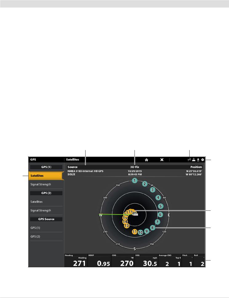
Use the GPS tool to check the GPS reception. The GPS tool provides two ways to view the satellites communicating with the GPS Receiver. Yellow indicates that the satellite is being used to determine your current position. Teal indicates that the satellite is being monitored but not used. The following data is also displayed:
•Position (latitude and longitude)
•GPS Fix Type: reported as No Fix, 2D Fix, 3D Fix, or Enhanced. An Enhanced fix has been augmented using information from WAAS, EGNOS, or MSAS. A 3D or Enhanced Fix is required for navigation.
•HDOP (the Horizontal Dilution of Precision): a GPS system parameter which depends on the current satellite configuration. HDOP is used to calculate the Estimated Position Error.
Open the GPS Tool
If there is more than one control head installed on the network, select the control head that is connected directly to the GPS receiver.
1.Press the HOME key.
2.Select the GPS tool.
Review Satellites and Signal Strength
1.Under GPS (1), select Satellites.
2.Under GPS (1), select Signal Strength.
GPS (1) Satellite Sky Chart
selected GPS source |
fix type |
GPS status icon |
status bar
satellites communicating to GPS (1)
used satellite (yellow)
monitored satellite (teal)
digital readouts
GPS (1) Satellites shows a sky chart and numerical data from the selected GPS receiver
17 |
Getting Started |

Signal Strength (bar graph)
selected GPS source |
fix type |
GPS status icon |
status bar
boat position (latitude/ longitude)
satellites signal strength GPS (1)
monitored satellite (teal) and strength level
used satellite (yellow) and strength level
digital readouts
Signal Strength (GPS 1/GPS 2): displays vertical bar graphs indicating the satellite signal strengths with the respecting CNO (Carrier-to-Noise) value (0 to 60).
GPS (1) and GPS (2) Sources
You can also manually change which GPS receiver is the selected source for GPS (1) or GPS (2). To change the GPS sources, see
Set up your Humminbird Network.
GPS (1) provides position data, Speed over Ground (SOG), Course over Ground (COG), waypoints, routes, tracks, and navigation calculations to the control head.
GPS (2) provides position data that is displayed in the GPS (2) data box.
Getting Started |
18 |
2 | Check Sensor Reception and Connections
If you’ve connected other separate-purchase equipment to the control head network, such as AIS, Compass/Heading Sensor, Radar, i-Pilot Link, 360 Imaging, and more, use these instructions to confirm the equipment is detected and communicating with the control head.
1.Press the HOME key.
2.Review the top, right corner of the status bar.
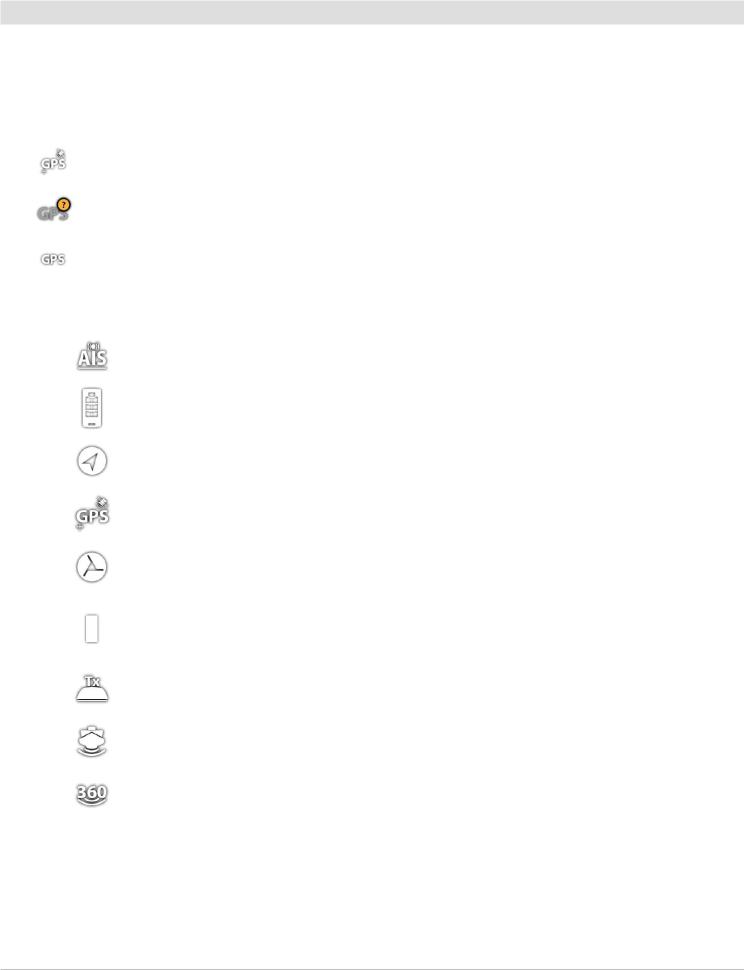
Detected and Active: If a sensor is active and transmitting/receiving, it will be white. See the table below.
Connected but not Detected or Active: If a sensor is not detected on the network, or not transmitting/receiving, it will be completely gray.
Connected but not Transmitting/Receiving: If a sensor is detected, but is not transmitting/receiving, the icon will be partially gray. In this illustration, the GPS receiver is detected, but it doesn’t have a GPS fix. This feature will vary with the type of icon represented.
Active Status Icon |
Sensor |
Icon Description |
|
|
|
|
AIS |
AIS is on and receiving targets. |
|
|
|
|
Wireless Remote |
The Bluetooth wireless remote is connected. |
|
|
|
|
Compass |
The selected compass/heading sensor is on and heading data is being |
|
received. |
|
|
|
|
|
|
|
|
GPS |
The GPS receiver is detected and a GPS fix has been obtained. |
|
|
|
|
i-Pilot Link |
i-Pilot Link is connected, enabled, and actively navigating. |
|
|
|
|
|
The Talon is connected and stowed. Download the Bluetooth Talon |
|
Bluetooth Talon |
Accessory Manual from our Web site at humminbird.com for |
|
|
additional Talon status icons. |
|
|
|
|
Radar |
The selected radar source is detected and transmitting. |
|
|
|
|
2D Sonar |
The selected 2D sonar source is detected and pinging. |
|
|
|
|
360 Imaging Sonar |
The 360 Imaging transducer is pinging data. |
|
|
|
3.If the sensors are active, your system is ready for use on the water.
For additional system status, select Home > Settings > Network > System Info.
If you have connected an accessory to the control head, and the icon is not displaying in the system status bar, check the installation of the accessory and the cable connection to the control head.
To change the NMEA 2000 network or multi-control head network sources, see Set up a NMEA 2000 Network and Set up your Humminbird Network.
19 |
Getting Started |

3 | Start Radar Transmission (connected Radar source required)
For more information about Humminbird CHIRP Radar and Humminbird Radar, see Radar Overview.
WARNING! The radar should be configured by a qualified radar technician after installation or equipment repair. See Installation Information: Configure Humminbird Radar.
1.Confirm the radar power source is turned on (breaker or switch).
2.Press the POWER key.
3.Humminbird CHIRP Radar: Select Radar > Standby. Press the POWER key again, and select Radar > Transmit.
Humminbird Radar: Select Radar Transmit. Tap the on/o button, or press the ENTER key, to turn it on.
4 | Pair a Bluetooth supported Mobile Device with the Control Head
Use |
llowing instructions to pair a mobile device (phone or tablet) to the control head using Bluetooth wireless technology. |
TE: If you have a Bluetooth Talon or the Bluetooth Wireless Remote (separate purchases required), see the accessory erations manual for each product for pairing instructions. Operations manuals can be downloaded from our Web site at
humminbird.com.
TE: WiFi or cellular data must be enabled on your device.
Enable Bluetooth on your Device
1.Open the Settings menu on your device.
2.Select Bluetooth.
3.Select On.
Pair the Phone with the Control Head
1.Press the HOME key.
2.Select the Bluetooth tool.
3.Select Connect Phone.
4.Under Device List, select your phone name.
It may take a moment for your phone name to appear in the menu.
5.Follow the on-screen prompts to complete the pairing process.
6.Check your phone. When prompted, tap Pair on your phone.
7.In your phone Settings menu, turn on Show Notifications.
8.Turn Connection On/O : Under Phone, select your phone name and tap the on/o button.
Forget Device: To remove the paired device, select Forget Device.
Getting Started |
20 |
Pairing a Mobile Phone to the SOLIX
 Turn paired phone connection
Bluetooth on/off. settings
 device list
The status bar indicates the SOLIX is actively searching for Bluetooth devices.
Change the Phone Bluetooth Notification Settings
Use the following instructions to select an alert format on the control head or turn o alerts.
1.Under the Phone Bluetooth menu, select Settings.
 NOTE: In your phone Settings menu, confirm that Bluetooth is turned on and Show Notifications is turned on.
2.Select Text Message Alerts or Phone Call Alerts.
Tap to select an alert format. To turn o notifications, select o .
3.Turn Sounds On/O : Select Sounds. Select on or o .
Review Phone Bluetooth Notifications
View phone notifications on the Home screen.
21 |
Getting Started |
5 | Set Alarms
When an alarm is turned on, an alert will sound or display on the control head to indicate the threshold has been exceeded.
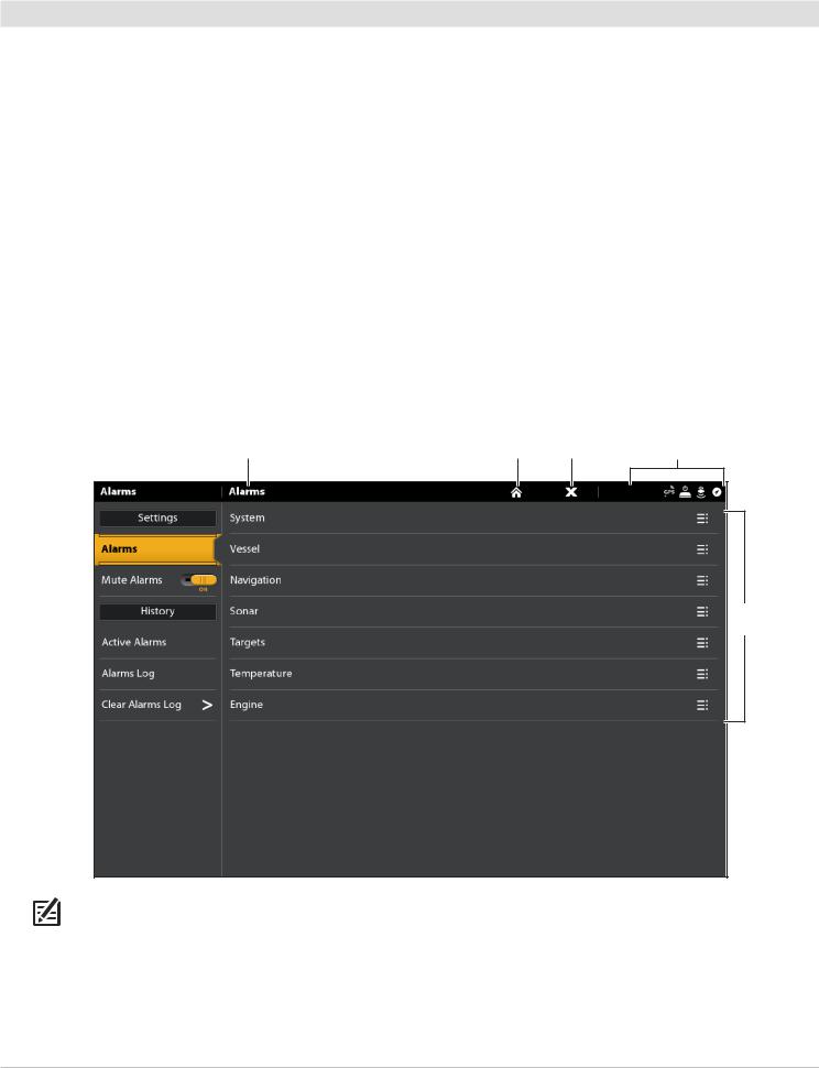
1.Press the HOME key. Select Alarms.
2.Under Settings, select Alarms.
If the control head is connected to the Humminbird network, select Local Alarms (control head only) or Networked Alarms (alarms shared across control heads). See Set up your Humminbird Network for more information.
3.Select an alarm category.
4.Select an alarm name.
5.On/O : Tap the on/o button, or press the ENTER key, to turn on the alarm.
6.Adjust the alarm threshold.
Touch Screen: Press and hold the slider, or drag the slider.
Keypad: Press and hold the ENTER key, or turn the Rotary dial.
7.Repeat steps 3 through 6 for each alarm you want to set.
Setting an Alarm
selected category |
home |
close |
status bar |
menu options
NOTE: See The Menu System: Tips for Using the Status Bar for more details.
Getting Started |
22 |

The available alarms are determined by the connected equipment, so your control head may provide more or less options than the information shown here.
System |
Voltage, Lost Heading (compass/heading sensor required), etc. |
|
|
|
|
Vessel |
Drift Limit, SOG (Speed over Ground), STW (Speed through Water), etc. Also, see Views: |
|
Understand the Data Box Digital Readouts for more information. |
||
|
||
|
|
|
Navigation |
See Chart Overview: Navigation Alarms Overview for details. |
|
|
|
|
Sonar |
See Sonar Overview: Sonar Alarms for details. |
|
|
|
|
Radar |
See Radar Overview: Radar Alarms for details. |
|
|
|
|
Temperature |
Temp (High) or Temp (Low). To change the Temperature sources, see Installation Information: |
|
Set up your Humminbird Network. |
||
|
||
|
|
|
Engine |
Low Fuel, Engine Temp, Oil Level, Coolant Level, Check Engine, etc. To change Engine and Fuel |
|
sources, see Installation Information: Set up a NMEA 2000 Network. |
||
|
||
|
|
Change System Settings
Your control head was configured during the installation setup. To change the system settings such as the backlight, key sounds, units of measurement, and the time and date format (including Daylight Saving Time), select Settings from the Home screen. See
Manage your Control Head for more information.
1.Press the HOME key.
2.Select Settings.
3.Select General.
 NOTE: To reconfigure the control head with the Setup Guide, select the Setup Guide tool from the Home screen.
Set up Sonar
Proceed to the Sonar Overview section.
Select the Map Source
Proceed to the Chart Overview section.
23 |
Getting Started |

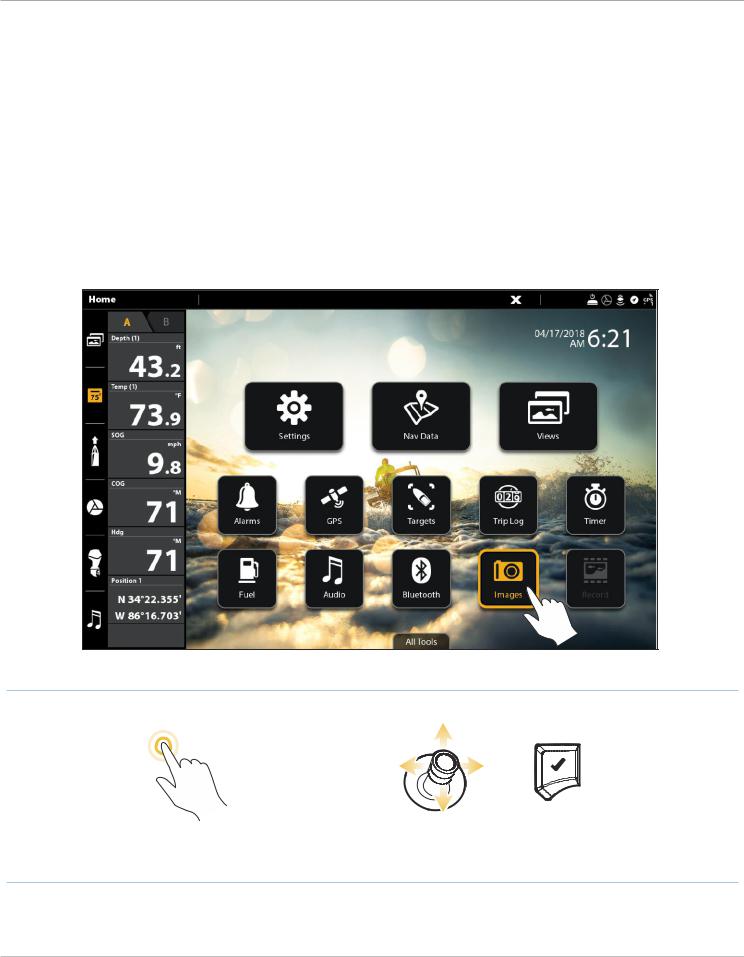
THE HOME SCREEN
The Home screen is the main control center for your control head. Use the Home screen to access the control head settings, navigation data, views, alarms, and other tools.
•The tools, views, and side bar widgets available on the Home screen are determined by the equipment attached to the control head network.
•The Home screen wallpaper (background) can be customized using the Images tool.
•Pair your Bluetooth capable control head and mobile device to receive text message and phone call alerts on your Home screen.
Open the Home Screen
Touch Screen |
Keypad |
1. With a view displayed on-screen, touch the screen with |
1. Press the HOME key. |
two fingers and swipe down. |
|
The SOLIX Home Screen
favorite views widget |
Bluetooth notifications (with paired mobile device) |
STATUS BAR |
 time and date
SIDE BAR widgets
TOOLS
|
customizable Home screen |
select to view additional tools |
|
wallpaper (background) |
|
|
|
|
|
|
|
OR
Swipe down to open
Press the HOME key
from any view
Home Screen |
24 |
Navigate the Home Screen
See the instructions and screenshot below to better understand the Home screen layout.
Touch Screen
Open a Tool: Tap the tool icon.
Open a Widget: Tap the widget icon (in the side bar).
View Additional Tools: Tap All Tools.
Close (return to the previous view): Tap the X icon in the status bar.
Keypad
Select (Open): Use the Joystick to select a menu, tool, or widget. Press the ENTER key to open it.
Open a Widget: Press the PANE key. Use the Joystick to select the widget icon and press the ENTER key to open it.
View Additional Tools: Use the Joystick to select All Tools. Press the ENTER key.
Close (return to the previous view): Press the EXIT key.
Opening a Tool
OR
Tap to Select (Open) |
Select |
Open |
25 |
Home Screen |

Tools
Tools allow you to manage the control head network operations and saved data. When you connect an accessory to the control head, a related tool may also be displayed.
|
Select Settings to change general system settings such as the backlight, units of measurement, and |
|
Settings |
the time and date format. You can also use this menu to change the main settings for each application |
|
|
(Sonar, Chart, Radar, etc.). See each related section of this manual for details. |
|
|
|
|
|
Select Nav Data to manage your saved waypoints, routes, tracks, and groups. You can create new |
|
Nav Data |
navigation data from this screen, edit your saved navigation data, or start navigation (see Manage your |
|
Navigation Data). |
||
|
Required Equipment: GPS receiver (internal or external) |
|
|
|
|
Views |
Select Views to access the complete set of views available on your control head. You can edit views, |
|
create your own views, and save your favorite views. See Views for more information. |
||
|
||
|
|
|
|
Select Alarms to view the alarm log, mute alarm sounds, and set the alarms for the individual |
|
Alarms |
applications. To set up individual alarms for navigation, sonar, radar, AIS, etc., see each related section |
|
|
of this manual for details. For example, for radar alarm settings, see Radar Alarms. |
|
|
|
|
|
Select GPS to review the signal strength of the GPS receivers (“sensors”) connected to the system. The |
|
|
tool shows the satellites in the area, the positions, and the signal strength for each one. You can also |
|
GPS |
designate a primary and secondary GPS source from this tool. See Getting Started, Installation |
|
Information, and Set up your Humminbird Network. |
||
|
||
|
Required Equipment: GPS receiver (internal or external) |
|
|
|
|
Targets |
Select Targets to manage AIS and MARPA targets. See AIS and MARPA for more information. |
|
Required Equipment: AIS or Radar, GPS receiver (internal or external), and compass/heading sensor |
||
|
||
|
|
|
|
Select Trip Log to display Speed over Ground (SOG), timer for elapsed time, distance traveled since last |
|
Trip Log |
reset, average speed, and trip fuel. You can also reset the trip log to zero and review trend data from |
|
this tool. |
||
|
Required Equipment: GPS receiver (internal or external) |
|
|
|
|
Timer |
Select Timer to set an alarm clock for a selected time of day, use the countdown timer, or use the |
|
stopwatch. You can set more than one alarm clock. |
||
|
||
|
|
|
|
Select Fuel to review the fuel log for NMEA 2000 fuel sensors connected to the network. This tool provides |
|
Fuel* |
refuel alerts and displays the fuel level in graphical form. See Set up a NMEA 2000 Network for details. |
|
|
||
|
*Required Equipment: NMEA 2000 tank sensor and/or fuel flow rate sensor |
|
|
|
|
|
|
Home Screen |
26 |

Audio* |
Select Audio to listen to AM/FM radio or audio files saved to a USB stick, iPod, etc. |
|
*Required Equipment: compatible audio system |
||
|
||
|
|
|
|
Select Bluetooth to pair your mobile phone and/or Bluetooth wireless remote (separate purchase |
|
Bluetooth |
required) to the control head. You can also assign key functions for the Bluetooth remote from this tool. |
|
See your installation guide for details. To pair your mobile phone to the control head, see Getting Started. |
||
|
Required Equipment: mobile phone (with Bluetooth), Bluetooth remote |
|
|
|
|
|
Select Images to manage your screen snapshots. When a screen snapshot is taken, a waypoint can also |
|
|
be saved at the current position. You can also choose to save the image on the control head or to an SD |
|
Images |
or microSD card. Also, screen snapshots and pictures from your camera’s SD card (JPG Files) can be |
|
|
displayed as the Home screen wallpaper and in a slideshow from this tool. See Getting Started and |
|
|
Images Tool for more information. |
|
|
|
|
|
Select Record to start a sonar recording or select a save location. You can also watch a sonar recording |
|
Record |
from the perspective of a 2D, SI, or DI View, depending on the capabilities of your model. See Sonar |
|
Recording for more information. |
||
|
Required Equipment: transducer, black box sonar |
|
|
|
|
Sun + Moon |
Select Sun + Moon to review the sunrise and sunset for today or the date you select. The Moon data |
|
provides the rise and set of the moon and moon phases. |
||
|
||
|
|
|
|
Select Files to update the software for the control head or connected accessories. You can also import |
|
|
and export navigation data from this tool, and you can import and export menu settings. Radar |
|
Files |
installation settings can be managed from this tool, but only authorized radar technicians should use |
|
this menu. See the following sections: Manage your Navigation Data and Manage your Control Head. |
||
|
||
|
Required Equipment: SD or microSD card (depending on your control head model) |
|
|
|
|
|
Select Setup Guide, and the control head will guide you through the basic configuration settings for your |
|
Setup Guide |
control head, including units of measurement, language, transducer source, map source, and vessel |
|
settings. See your installation guide for details. To change the settings after setup, select Home > |
||
|
||
|
Settings. |
|
|
|
|
|
Select Tides to review information for the nearest tide station to your present position. The tool includes |
|
|
the position of the station and the times of the high and low tides for today’s date. A tide graph is also |
|
Tides |
displayed showing the rise and fall of the tides for the 24 hour time period encompassing the date. You |
|
can also search data for a selected date. |
||
|
||
|
Required Map Source: Navionics |
|
|
|
|
|
Select Currents to review information for the nearest current station to your present position. Two graphs |
|
Currents |
are also presented that show the time, direction, and flow speed of the current changes for the 24 hour |
|
time period of today’s date. You can also search data for a selected date. |
||
|
Required Map Source: Navionics |
|
|
|
27 |
Home Screen |

Side Bar Widgets
The side bar includes widgets that allow you to quickly access your favorite views, data bars, and digital remotes for networked accessories, like i-Pilot Link and Talon.
The side bar is set to always display on the Home screen, but it can be hidden in other views. See Edit the On-Screen View: Turn the Side Bar On/O .
Opening a Widget
engine data widget
selected data box
(highlighted in yellow)
submenu with additional data boxes
selected widget
OR
Tap to Select (Open) |
Select the Side Bar |
Select a Widget |
Open |
|
|
|
|
Home Screen |
28 |
Available Side Bar Widgets
When you connect an accessory to the control head, a related widget may also be displayed in the side bar.
If you have connected an accessory to the control head, and the icon is not displaying in the system status bar, check the installation of the accessory and the cable connection to the control head.
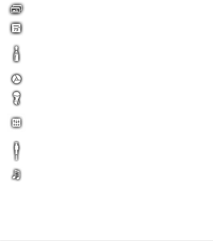
Widget Icon |
Name |
Widget Function |
|
|
|
|
|
Allows you to create a list of your favorite views. There are two tabs, which allow |
|
Favorite Views |
you save up to 10 views. Use the widget to quickly display your favorite views (see |
|
|
Views). |
|
|
|
|
|
Displays the standard Data Bar with data box readouts. There are two tabs and |
|
Data Bar |
each data box can be customized (see Views: Understand the Data Box Digital |
|
|
Readouts). |
|
|
|
|
|
Displays the Nav (Navigation) Data Bar with digital readout boxes for navigation. |
|
|
There are two tabs and each data box can be customized (see Views: Understand |
|
Navigation Data Bar |
the Data Box Digital Readouts). |
|
|
|
|
|
*With a connected i-Pilot Link, this selection will display the i-Pilot Link Navigation |
|
|
Data Bar. |
|
|
|
|
i-Pilot Link* |
Displays the i-Pilot Link digital remote. |
|
|
|
|
Engine Data* |
Displays engine data from the connected NMEA 2000 network. Some data boxes |
|
include built-in submenus to view additional data. |
|
|
|
|
|
|
|
|
|
Displays the digital switch panel for your boat. Use this widget to quickly access |
|
Digital Switching* |
settings for your boat’s electrical and connected systems, such as lights, fans, |
|
horns, bilge, etc. |
|
|
|
See our Web site for compatibility information. |
|
|
|
|
Talon* |
Displays the Talon digital remote, which includes quick access menus to deploy |
|
and retract the Talon, change the anchor mode, turn the work light on/off, etc. |
|
|
|
|
|
|
|
|
Audio* |
Displays the audio settings for a connected audio accessory. |
|
|
|
|
|
*separate purchase accessory |
29 |
Home Screen |

Status Bar
The status bar is located at the top of the screen. It changes to match the on-screen view and operation mode.
In the following illustration, the information in the status bar corresponds with the Chart View displayed on-screen. You can tap the icon in the status bar to open a menu, return to the Home screen, close a menu, or make a selection. You can also use the corresponding keys.
Status Bar
|
|
touch menus change to match the on-screen view and status |
sensor status |
|
||||
|
|
|
|
|
|
|
|
|
|
|
|
|
|
|
|
|
|
|
|
|
|
|
|
|
|
|
|
|
|
|
|
|
|
|
|
Tap, or press the MENU key, to open the X-Press Menu for the on-screen view.
Tap, or press the POWER key, to open the Power X-Press Menu
Chart View Status Bar Menus
Chart View Status Bar Menus
|
chart orientation chart mode |
AutoChart Live center vessel show cursor |
|||||
|
|
|
|
|
|
|
|
|
|
|
|
|
|
|
|
|
|
|
|
|
|
|
|
|
|
|
|
|
|
|
|
Tap, or press the MENU key, to open the X-Press Menu.
Sonar View Status Bar Menus
Sonar View Status Bar Menus
sonar display frequency SwitchFire™ sonar colors zoom
Tap, or press the MENU key, to open the X-Press Menu.
Home Screen |
30 |
 Loading...