


531524-1_A - 717 & 727 Man_Eng.qxp 9/30/2006 7:23 PM Page 1
700 Series™
Operations Manual
531524-1
531524-1_A - 717 & 727 Man_Eng.qxp 9/30/2006 7:23 PM Page 2
Thank You!
Thank you for choosing Humminbird®, America's #1 name in fishfinders. Humminbird® has built its reputation by designing and manufacturing topquality, thoroughly reliable marine equipment. Your Humminbird® is designed for trouble-free use in even the harshest marine environment. In the unlikely event that your Humminbird® does require repairs, we offer an exclusive Service Policy - free of charge during the first year after purchase, and available at a reasonable rate after the one-year period. For complete details, see the separate warranty card included with your unit. We encourage you to read this operations manual carefully in order to get full benefit from all the features and applications of your Humminbird® product.
Contact our Customer Resource Center at either 1-800-633-1468 or visit our website at www.humminbird.com.
WARNING! This device should not be used as a navigational aid to prevent collision, grounding, boat damage, or personal injury. When the boat is moving, water depth may change too quickly to allow time for you to react. Always operate the boat at very slow speeds if you suspect shallow water or submerged objects.
WARNING! Disassembly and repair of this electronic unit should only be performed by authorized service personnel. Any modification of the serial number or attempt to repair the original equipment or accessories by unauthorized individuals will void the warranty. Handling and/or opening this unit may result in exposure to lead, in the form of solder.
WARNING! This product contains lead, a chemical known to the state of California to cause cancer, birth defects and other reproductive harm.
NOTE: Some features discussed in this manual require a separate purchase, and some features are only available on international models. Every effort has been made to clearly identify those features. Please read the manual carefully in order to understand the full capabilities of your model.
of
©
i

531524-1_A - 717 & 727 Man_Eng.qxp 9/30/2006 7:23 PM Page 3
Table of Contents
How Sonar Works |
1 |
DualBeam PLUS™ Sonar . . . . . . . . . . . . . . . . . . . . . . . . . . . . . . . . . . . . . . . . . . . . . . . . . . . . . 3 QuadraBeam PLUS™ Sonar (with optional-purchase QuadraBeam PLUS™ transducer) . . . . 4 WideSide® Sonar (with optional-purchase WideSide® transducer) . . . . . . . . . . . . . . . . . . . . . 5 Universal Sonar 2 . . . . . . . . . . . . . . . . . . . . . . . . . . . . . . . . . . . . . . . . . . . . . . . . . . . . . . . . . . . 6
What’s On the Display |
7 |
Views |
9 |
Sonar View . . . . . . . . . . . . . . . . . . . . . . . . . . . . . . . . . . . . . . . . . . . . . . . . . . . . . . . . . . . . . . . 10 Understanding Sonar History . . . . . . . . . . . . . . . . . . . . . . . . . . . . . . . . . . . . . . . . . . . . . . . . 11 Real Time Sonar (RTS®) Window . . . . . . . . . . . . . . . . . . . . . . . . . . . . . . . . . . . . . . . . . . . . . 12 Freeze Frame and Cursor . . . . . . . . . . . . . . . . . . . . . . . . . . . . . . . . . . . . . . . . . . . . . . . . . . . . 12 Bottom Presentation . . . . . . . . . . . . . . . . . . . . . . . . . . . . . . . . . . . . . . . . . . . . . . . . . . . . . . . 13 Sonar Zoom View . . . . . . . . . . . . . . . . . . . . . . . . . . . . . . . . . . . . . . . . . . . . . . . . . . . . . . . . . . 16 200/83 kHz Split Sonar View . . . . . . . . . . . . . . . . . . . . . . . . . . . . . . . . . . . . . . . . . . . . . . . . . 17 Big Digits View . . . . . . . . . . . . . . . . . . . . . . . . . . . . . . . . . . . . . . . . . . . . . . . . . . . . . . . . . . . . 18 Circular Flasher View . . . . . . . . . . . . . . . . . . . . . . . . . . . . . . . . . . . . . . . . . . . . . . . . . . . . . . . 19 Side Beam View (with optional-purchase QuadraBeam PLUS™ transducer) . . . . . . . . . . . . 20 WideSide® View (with optional-purchase WideSide® transducer) . . . . . . . . . . . . . . . . . . . . . 23
Key Functions |
24 |
POWER/LIGHT Key . . . . . . . . . . . . . . . . . . . . . . . . . . . . . . . . . . . . . . . . . . . . . . . . . . . . . . . . . 24
VIEW Key . . . . . . . . . . . . . . . . . . . . . . . . . . . . . . . . . . . . . . . . . . . . . . . . . . . . . . . . . . . . . . . . 24
MENU Key . . . . . . . . . . . . . . . . . . . . . . . . . . . . . . . . . . . . . . . . . . . . . . . . . . . . . . . . . . . . . . . 25
4-WAY Cursor Control Key . . . . . . . . . . . . . . . . . . . . . . . . . . . . . . . . . . . . . . . . . . . . . . . . . . . 25
EXIT Key . . . . . . . . . . . . . . . . . . . . . . . . . . . . . . . . . . . . . . . . . . . . . . . . . . . . . . . . . . . . . . . . . 26
Accessory Bus |
27 |
Powering Up the Unit |
28 |
The Menu System |
29 |
Start-Up Options Menu |
31 |
Normal Operation . . . . . . . . . . . . . . . . . . . . . . . . . . . . . . . . . . . . . . . . . . . . . . . . . . . . . . . . . . 31
Simulator . . . . . . . . . . . . . . . . . . . . . . . . . . . . . . . . . . . . . . . . . . . . . . . . . . . . . . . . . . . . . . . . 32
System Status . . . . . . . . . . . . . . . . . . . . . . . . . . . . . . . . . . . . . . . . . . . . . . . . . . . . . . . . . . . . 33
Self Test. . . . . . . . . . . . . . . . . . . . . . . . . . . . . . . . . . . . . . . . . . . . . . . . . . . . . . . . . . . . . . . . . . 33
Accessory Test. . . . . . . . . . . . . . . . . . . . . . . . . . . . . . . . . . . . . . . . . . . . . . . . . . . . . . . . . . . . . 34
PC Connect (with PC Connect Cable Only) . . . . . . . . . . . . . . . . . . . . . . . . . . . . . . . . . . . . . . 34
ii

531524-1_A - 717 & 727 Man_Eng.qxp 9/30/2006 7:23 PM Page 4
Table of Contents
Sonar X-Press™ Menu |
35 |
Side (WideSide® transducer: WideSide® view only) . . . . . . . . . . . . . . . . . . . . . . . . . . . . . . . . 36 Sensitivity . . . . . . . . . . . . . . . . . . . . . . . . . . . . . . . . . . . . . . . . . . . . . . . . . . . . . . . . . . . . . . . . 37 Upper Range (Advanced: Sonar, Split Sonar, Big Digits and Circular Flasher Views only) . . 38 Lower Range . . . . . . . . . . . . . . . . . . . . . . . . . . . . . . . . . . . . . . . . . . . . . . . . . . . . . . . . . . . . . 39 Side Beam Range (WideSide® transducer: WideSide® view only) . . . . . . . . . . . . . . . . . . . . 40 Chart Speed . . . . . . . . . . . . . . . . . . . . . . . . . . . . . . . . . . . . . . . . . . . . . . . . . . . . . . . . . . . . . . 41 Bottom View . . . . . . . . . . . . . . . . . . . . . . . . . . . . . . . . . . . . . . . . . . . . . . . . . . . . . . . . . . . . . . 41 Quad Layout (with optional-purchase QuadraBeam PLUS™ transducer,
Side Beam View only) . . . . . . . . . . . . . . . . . . . . . . . . . . . . . . . . . . . . . . . . . . . . . . . . . . . . . . . 42 Zoom Level (Sonar Zoom view only) . . . . . . . . . . . . . . . . . . . . . . . . . . . . . . . . . . . . . . . . . . . 43 Bottom Lock . . . . . . . . . . . . . . . . . . . . . . . . . . . . . . . . . . . . . . . . . . . . . . . . . . . . . . . . . . . . . . 43 Bottom Range (Sonar Zoom View only, when Bottom Lock is On) . . . . . . . . . . . . . . . . . . . . 44
Sonar Menu Tab |
45 |
Beam Select . . . . . . . . . . . . . . . . . . . . . . . . . . . . . . . . . . . . . . . . . . . . . . . . . . . . . . . . . . . . . . 46 Fish ID+™ . . . . . . . . . . . . . . . . . . . . . . . . . . . . . . . . . . . . . . . . . . . . . . . . . . . . . . . . . . . . . . . . 47 Fish ID Sensitivity . . . . . . . . . . . . . . . . . . . . . . . . . . . . . . . . . . . . . . . . . . . . . . . . . . . . . . . . . . 48 Real Time Sonar (RTS®) Window . . . . . . . . . . . . . . . . . . . . . . . . . . . . . . . . . . . . . . . . . . . . . 48 Zoom Width . . . . . . . . . . . . . . . . . . . . . . . . . . . . . . . . . . . . . . . . . . . . . . . . . . . . . . . . . . . . . . 49 83 kHz Sensitivity (Advanced) . . . . . . . . . . . . . . . . . . . . . . . . . . . . . . . . . . . . . . . . . . . . . . . . 49 455 kHz Sensitivity (Advanced, with QuadraBeam PLUS™ transducer) . . . . . . . . . . . . . . . . 50 WideSide® Sensitivity (Advanced, with WideSide® transducer) . . . . . . . . . . . . . . . . . . . . . . 51 Depth Lines (Advanced) . . . . . . . . . . . . . . . . . . . . . . . . . . . . . . . . . . . . . . . . . . . . . . . . . . . . . 52 Surface Clutter (Advanced) . . . . . . . . . . . . . . . . . . . . . . . . . . . . . . . . . . . . . . . . . . . . . . . . . . 53 Noise Filter (Advanced) . . . . . . . . . . . . . . . . . . . . . . . . . . . . . . . . . . . . . . . . . . . . . . . . . . . . . 54 Max Depth (Advanced) . . . . . . . . . . . . . . . . . . . . . . . . . . . . . . . . . . . . . . . . . . . . . . . . . . . . . 54 Water Type (Advanced) . . . . . . . . . . . . . . . . . . . . . . . . . . . . . . . . . . . . . . . . . . . . . . . . . . . . . 55 Transducer Select . . . . . . . . . . . . . . . . . . . . . . . . . . . . . . . . . . . . . . . . . . . . . . . . . . . . . . . . . . 56
Alarms Menu Tab |
57 |
Depth Alarm . . . . . . . . . . . . . . . . . . . . . . . . . . . . . . . . . . . . . . . . . . . . . . . . . . . . . . . . . . . . . . 58 Fish ID Alarm. . . . . . . . . . . . . . . . . . . . . . . . . . . . . . . . . . . . . . . . . . . . . . . . . . . . . . . . . . . . . . 58 Low Battery Alarm . . . . . . . . . . . . . . . . . . . . . . . . . . . . . . . . . . . . . . . . . . . . . . . . . . . . . . . . . 59 Aux. Temp. Alarm (with optional-purchase temp. probe or Temp/Speed only) . . . . . . . . . . . 59 Temp Alarm . . . . . . . . . . . . . . . . . . . . . . . . . . . . . . . . . . . . . . . . . . . . . . . . . . . . . . . . . . . . . . . 60 Alarm Tone . . . . . . . . . . . . . . . . . . . . . . . . . . . . . . . . . . . . . . . . . . . . . . . . . . . . . . . . . . . . . . . 60
Setup Menu Tab |
61 |
Units - Depth . . . . . . . . . . . . . . . . . . . . . . . . . . . . . . . . . . . . . . . . . . . . . . . . . . . . . . . . . . . . . 62 Units - Temp (International only) . . . . . . . . . . . . . . . . . . . . . . . . . . . . . . . . . . . . . . . . . . . . . . 62
iii

531524-1_A - 717 & 727 Man_Eng.qxp 9/30/2006 |
7:23 PM Page 5 |
Table of Contents |
|
Units - Distance (with Temp/Speed or GPS receiver) . . . . . . . . . . . |
. . . . . . . . . . . . . . . . . . . 62 |
Units - Speed (with Temp/Speed or GPS receiver) . . . . . . . . . . . . . . |
. . . . . . . . . . . . . . . . . . 63 |
User Mode . . . . . . . . . . . . . . . . . . . . . . . . . . . . . . . . . . . . . . . . . . . . . |
. . . . . . . . . . . . . . . . . . 63 |
Language (International only) . . . . . . . . . . . . . . . . . . . . . . . . . . . . . . . |
. . . . . . . . . . . . . . . . . . 63 |
Triplog Reset (with Temp/Speed or GPS receiver) . . . . . . . . . . . . . . . |
. . . . . . . . . . . . . . . . . . 64 |
Restore Defaults . . . . . . . . . . . . . . . . . . . . . . . . . . . . . . . . . . . . . . . . . |
. . . . . . . . . . . . . . . . . . 64 |
Select Readouts (Advanced, Sonar view only) . . . . . . . . . . . . . . . . . |
. . . . . . . . . . . . . . . . . . 65 |
Depth Offset (Advanced). . . . . . . . . . . . . . . . . . . . . . . . . . . . . . . . . . . |
. . . . . . . . . . . . . . . . . . 67 |
Aux. Temp. Offset (Advanced; with |
|
optional-purchase temp. probe or Temp/Speed only) . . . . . . . . . . |
. . . . . . . . . . . . . . . . . . 67 |
Temp Offset (Advanced) . . . . . . . . . . . . . . . . . . . . . . . . . . . . . . . . . . . |
. . . . . . . . . . . . . . . . . . 68 |
Speed Calibration (Advanced, with Temp/Speed only) . . . . . . . . . . . |
. . . . . . . . . . . . . . . . . . 68 |
Digits Format (Advanced) . . . . . . . . . . . . . . . . . . . . . . . . . . . . . . . . . . . |
. . . . . . . . . . . . . . . . . . . 69 |
NMEA Output (Advanced). . . . . . . . . . . . . . . . . . . . . . . . . . . . . . . . . . |
. . . . . . . . . . . . . . . . . . 70 |
Views Menu Tab |
71 |
Accessories Menu Tab |
72 |
Troubleshooting |
73 |
700 Series™ Doesn’t Power Up. . . . . . . . . . . . . . . . . . . . . . . . . . . . . . . . . . . . . . . . . . . . . . . 73 700 Series™ Defaults to Simulator with a Transducer Attached . . . . . . . . . . . . . . . . . . . . 73 Display Problems . . . . . . . . . . . . . . . . . . . . . . . . . . . . . . . . . . . . . . . . . . . . . . . . . . . . . . . . . . 74 Finding the Cause of Noise . . . . . . . . . . . . . . . . . . . . . . . . . . . . . . . . . . . . . . . . . . . . . . . . . . 75
700 Series™ Fishing System Accessories |
76 |
Specifications |
78 |
Glossary |
81 |
Contact Humminbird® |
91 |
NOTE: Entries in this Table of Contents which list (International only) are only available on products sold outside of the US by our authorized International Distributors. To obtain a list of authorized International Distributors, please visit our website at www.humminbird.com or contact our Customer Resource Center at 1-800-633-1468to locate the distributor nearest you.
NOTE: Entries in this Table of Contents which list (with Temp/Speed or GPS Receiver), or (with PC Connect Cable Only) require the purchase of separate accessories. You can visit our website at www.humminbird.com to order these accessories online or contact our Customer Resource Center at 1-800-633-1468.
iv
531524-1_A - 717 & 727 Man_Eng.qxp 9/30/2006 7:23 PM Page 6
How Sonar Works
Sonar technology is based on sound waves. The 700 Series™ Fishing System uses sonar to locate and define structure, bottom contour and composition, as well as depth directly below the transducer.
Your 700 Series™ Fishing System sends a sound wave signal and determines distance by measuring the time between the transmission of the sound wave and when the sound wave is reflected off of an object; it then uses the reflected signal to interpret location, size, and composition of an object.
Sonar is very fast. A sound wave can travel from the surface to a depth of 240 ft (70 m) and back again in less than 1/4 of a second. It is unlikely that your boat can "outrun" this sonar signal.
SONAR is an acronym for SOund and NAvigation Ranging. Sonar utilizes precision sound pulses or "pings" which are emitted into the water in a teardrop-shaped beam.
The sound pulses "echo" back from objects in the water such as the bottom, fish and other submerged objects. The returned echoes are displayed on the LCD screen. Each time a new echo is received, the old echoes are moved across the LCD, creating a scrolling effect.
When all the echoes are viewed side by side, an easy to interpret "graph" of the bottom, fish and structure appears.
1
531524-1_A - 717 & 727 Man_Eng.qxp 9/30/2006 7:23 PM Page 7
The sound pulses are transmitted at various frequencies depending on the application. Very high frequencies (455 kHz) are used for greatest definition but the operating depth is limited. High frequencies (200 kHz) are commonly used on consumer sonar and provide a good balance between depth performance and resolution. Low frequencies (83 kHz) are typically used to achieve greater depth capability.
The power output is the amount of energy generated by the sonar transmitter. It is commonly measured using two methods:
•Root Mean Square (RMS) measures power output over the entire transmit cycle.
•Peak to Peak measures power output at the highest points.
The benefits of increased power output are the ability to detect smaller targets at greater distances, ability to overcome noise, better high speed performance and enhanced depth capability.
2
531524-1_A - 717 & 727 Man_Eng.qxp 9/30/2006 7:23 PM Page 8
DualBeam PLUS™ Sonar
Your 700 Series™ Fishing System uses a 200/83 kHz DualBeam PLUS™ sonar system with a wide (60°) area of coverage. DualBeam PLUS™ sonar has a narrowly focused 20° center beam, surrounded by a second beam of 60°, expanding your coverage to an area equal to your depth. In 20 feet of water, the wider beam covers an area 20 feet wide. The 20° center beam is focused on the bottom, to show you structure, weeds and cover. The 60° wide beam is hunting for fish in the wide coverage area. DualBeam PLUS™ sonar returns can be blended together, viewed separately or compared side-by-side. DualBeam PLUS™ is ideal for a wide range of conditions - from shallow to very deep water in both fresh and salt water. Depth capability is affected by such factors as boat speed, wave action, bottom hardness, water conditions and transducer installation.
3
531524-1_A - 717 & 727 Man_Eng.qxp 9/30/2006 7:23 PM Page 9
QuadraBeam PLUS™ Sonar
(with optional-purchase QuadraBeam PLUS™
transducer)
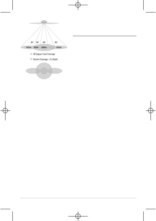
Your 700 Series™ Fishing System also supports QuadraBeam PLUS™ sonar with the purchase of an additional QuadraBeam PLUS™ transducer. QuadraBeam PLUS™ sonar provides an extremely wide 90° area of coverage. QuadraBeam PLUS™ starts with two fan-shaped 35° 455 kHz Side Structure locating sonar beams to spot fish, bait and structure to the left and right of the boat over an area of the bottom that’s always equal to twice your depth. For a detailed view below the boat, QuadraBeam PLUS™ uses DualBeam PLUS™ technology, with precision 20° and wide 60° beams. QuadraBeam PLUS™ finds more fish faster, and can even tell you where to put your bait by showing if fish are to the left, right or directly beneath your boat.
4
531524-1_A - 717 & 727 Man_Eng.qxp 9/30/2006 7:23 PM Page 10
WideSide® Sonar
(with optional-purchase WideSide® transducer)
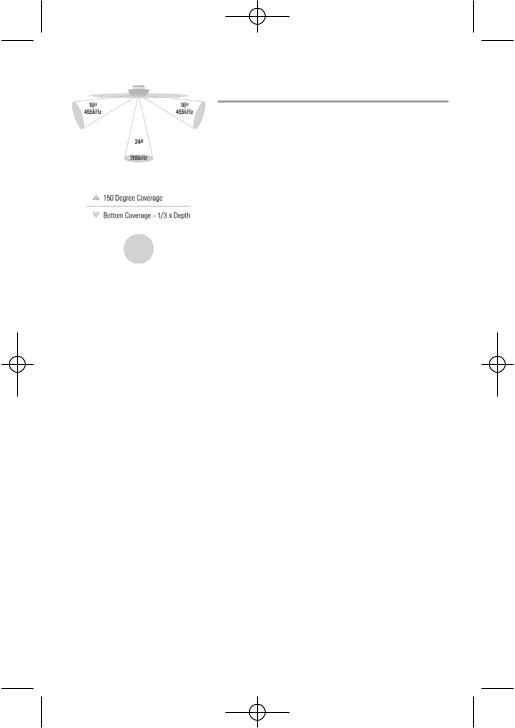
Your 700 Series™ Fishing System also supports WideSide® sonar with the purchase of an additional WideSide® transducer. The WideSide® transducer is a specialized "sidelooking" transducer that is extremely useful for bank fishing or looking for bait fish in open water. The WideSide® transducer uses three different sonar elements that transmit signals to the left, right and straight down from your boat. The downward beam is 200 kHz with a 24° area of coverage. This beam maintains a continuous digital depth readout from the bottom directly beneath your boat. The side beams are 455 kHz with a 16° area of coverage. The side-looking elements can be used independently, or together to locate targets near the surface of the water on either side of your boat.
5
531524-1_A - 717 & 727 Man_Eng.qxp 9/30/2006 7:23 PM Page 11
Universal Sonar 2
Your 700 Series™ Fishing System supports Universal Sonar 2, a state-of-the- art, integrated and protected transducer that is built into the lower unit of Minnkota trolling motors. With Universal Sonar 2, all wiring is concealed inside the indestructible composite shaft—out of sight and out of harm’s way, with no clamps, ties, or exposed wires. Universal Sonar 2 features new temperature sensing and the performance of DualBeam PLUS™ technology (available with all Humminbird® DualBeam PLUS™ models). An expanded view and greater bottom detail gives you a totally new perspective of the water below, along with optimal sonar performance to help you find fish.
6

531524-1_A - 717 & 727 Man_Eng.qxp 9/30/2006 7:23 PM Page 12
What’s On the Display
The 700 Series™ Fishing System can display a variety of useful information |
about the |
Depth - water depth; can be set to alarm when the water becomes too shallow.
Temperature - water surface temperature.
Bait Ball
Hard Bottom
Rocky Bottom
- when the sonar the bottom and the and back again. Use the second return hardness. Hard strong second return, show a very weak
Cursor - available in Freeze Frame and |
can be p |
to provide depth of a sonar return and |
bottom de |
Cursor Dialog Box - indicates cursor |
depth on |
of the bottom directly below the cursor. |
|
NOTE: Entries in this view that list (with Temp/Speed or GPS Receiver) are available if either |
device is |
information from the GPS receiver will be displayed on the view. |
|
7
531524-1_A - 717 & 727 Man_Eng.qxp 9/30/2006 7:23 PM Page 13
rmation |
about the area under and adjacent to your boat, including the following items: |
||||||||
|
|
|
|
|
|||||
Frame and |
can be positioned in the Sonar |
|
|
83 kHz, Wide Beam Hollow Fish Symbol |
|
||||
return and |
bottom depth below the cursor |
|
|
|
|
||||
|
|
|
|
||||||
|
|
|
|
||||||
|
|
|
|
|
|
|
|
|
|
|
|
|
|
|
|
|
|
|
|
|
|
|
|
|
|
|
|
|
|
|
|
|
|
|
|
|
|
|
|
|
|
|
|
|
|
|
|
|
|
|
|
|
|
|
|
|
|
|
|
|
|
|
|
|
|
|
|
|
|
200 kHz, Narrow Beam Shaded Fish Symbol
Window
ates cursor w the cursor
e if either |
device is connected to the Fishing System. If both devices are connected, then only the |
8
531524-1_A - 717 & 727 Man_Eng.qxp 9/30/2006 7:23 PM Page 14
Views
The views available on your Fishing System are:
•Sonar View
•Zoom View
•200/83 kHz Split Sonar View
•Big Digits View
•Circular Flasher View
•Side Beam View
•WideSide® View.
Sonar View is the default view. When the VIEW key is pressed, the display cycles through the available views. When the EXIT key is pressed, the display cycles through the available views in reverse order. Any view can be hidden or displayed as part of the view rotation using the Views Menu tab.
NOTE: When you change any menu settings that affect the sonar, the view will update immediately (i.e. you don’t have to exit the menu to apply the change to the screen). For instance, by switching between "Inverse" and "Structure ID®" from the X-Press™ Menu it is possible to quickly alternate between the two viewing methods.
NOTE: Side Beam View and WideSide® View require the purchase of the QuadraBeam PLUS™ transducer for the Side Beam View and the WideSide® transducer for the WideSide® View. You can visit our website at www.humminbird.com to order these accessories online or contact our Customer Resource Center at 1-800-633-1468.
9
531524-1_A - 717 & 727 Man_Eng.qxp 9/30/2006 7:23 PM Page 15
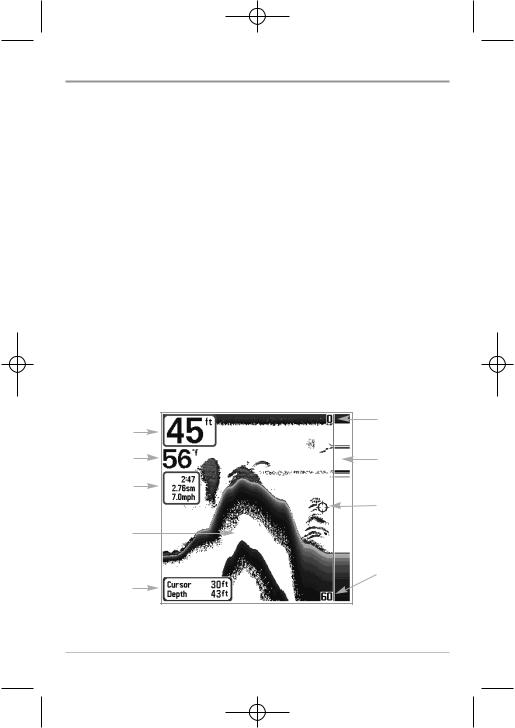
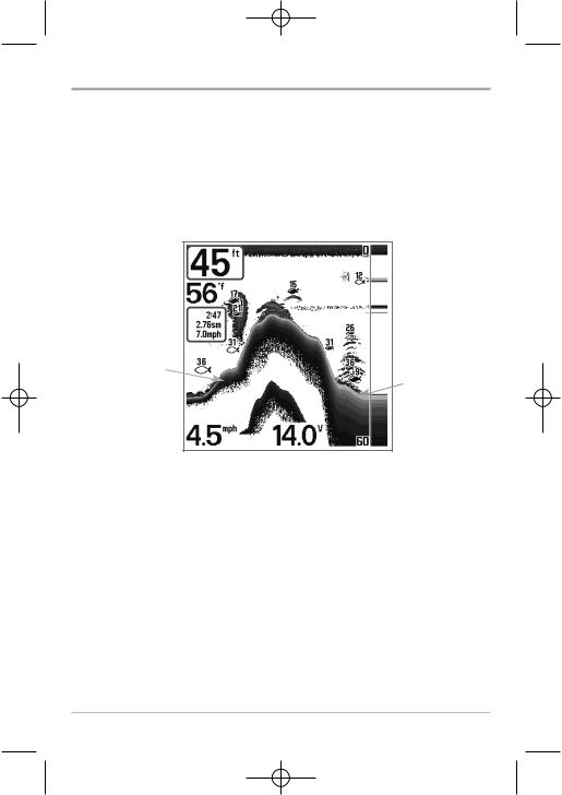
Sonar View
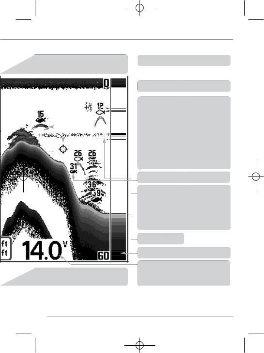
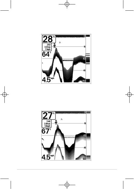
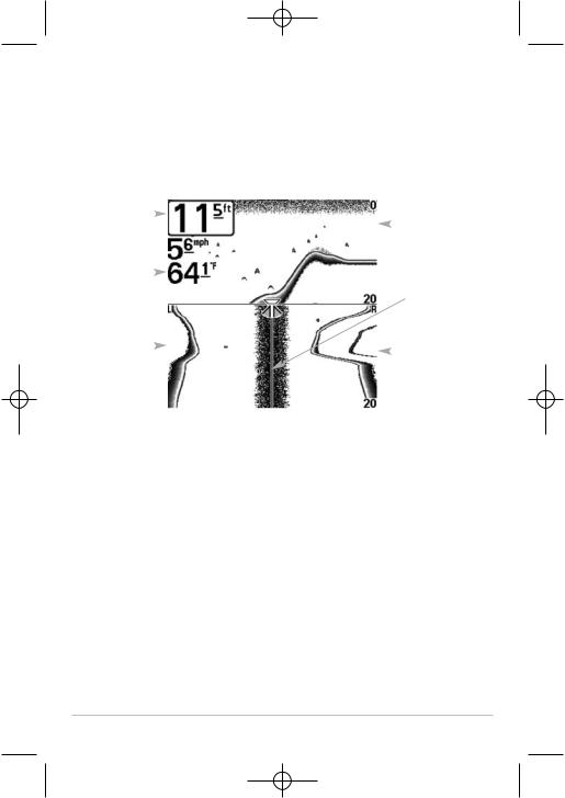
Sonar View presents a historical log of sonar returns. Depth is always displayed. Readouts for temperature and speed are automatically displayed if the appropriate accessory is connected. The most recent sonar returns are charted on the right side of the window; as new information is received, the older information is moved across the display to the left. A Digital Depth Readout is displayed in the upper left corner. A scale with Upper and Lower Depth Range readouts appears along the right edge of the Sonar View. The scale indicates the distance from the surface of the water to a depth range sufficient to show the bottom. Depth Range is automatically selected to keep the bottom visible on the display, although you can adjust it manually as well (see Sonar X-Press™ Menu). Six Digital Readouts display information from optional-purchase accessories.
These information boxes can be customized to show only the information desired (see Setup Menu Tab, Select Readouts).
NOTE: If the Depth number is flashing, it means that the unit is having trouble locating the bottom. This usually happens if the water is too deep, the transducer is out of the water, the boat is moving too fast, or for any other reason that the unit can’t accurately receive continuous data.
|
Sonar View |
|
Upper Depth |
Depth |
Range |
Temperature |
RTS® Window |
|
|
Triplog |
|
|
Cursor |
Sonar History |
|
Window |
|
Lower Depth
Cursor Range
Dialog Box
10
531524-1_A - 717 & 727 Man_Eng.qxp 9/30/2006 7:23 PM Page 16
Understanding Sonar History
It is important to understand the significance of the display. The display does NOT show a literal 3-dimensional representation of what is under the water. Each vertical band of data received by the control head and plotted on the display represents something that was detected by a sonar return at a particular time. As both the boat and the targets (fish) may be moving, the returns are only showing a particular segment of time when objects were detected, not exactly where those objects are in relation to other objects shown on the display.
11
531524-1_A - 717 & 727 Man_Eng.qxp 9/30/2006 7:23 PM Page 17
Real Time Sonar (RTS®) Window
A Real Time Sonar (RTS®) Window appears on the right side of the display in the Sonar View only. The RTS® Window always updates at the fastest rate possible for depth conditions and shows only the returns from the bottom, structure and fish that are within the transducer beam. The RTS® Window plots the depth and intensity of a sonar return (see Sonar Menu - RTS® Window).
The Narrow RTS® Window indicates the sonar intensity through the use of grayscale. The grayscale used matches the bottom view grayscale setting used in the sonar history window (i.e. Inverse, Structure ID®, WhiteLine®, Bottom Black). The depth of the sonar return is indicated by the vertical placement of the return on the display depth scale.
The Wide RTS® Window indicates the sonar intensity through the use of a bar graph. The length of the plotted return provides an indication of whether the return is weak or strong. The depth of the sonar return is indicated by the vertical placement of the return on the display depth scale. The Wide RTS® Window does not make use of grayscale.
Freeze Frame and Cursor
Freeze Frame - Pressing any arrow on the 4-WAY Cursor Control key will freeze the screen and a cursor will be displayed on the screen. The cursor can be positioned on the display using the 4-WAY Cursor Control key to determine the depth of any sonar return. The RTS® Window continues to update in Freeze Frame. In addition, see the effects of menu setting changes with Instant Image Update. Pressing EXIT will exit Freeze Frame and the display will start to scroll. Freeze Frame is available in Sonar, Sonar Zoom and 200/83 kHz Split Sonar Views.
12
531524-1_A - 717 & 727 Man_Eng.qxp 9/30/2006 7:23 PM Page 18
Bottom Presentation
As the boat moves, the unit charts the changes in depth on the display to create a profile of the Bottom Contour. The type of bottom can be determined from the return charted on the display. A Hard Bottom such as compacted sediment or flat rock appears as a thinner line across the display. A Soft Bottom such as mud or sand appears as a thicker line across the display. Rocky Bottoms have a broken, random appearance.
Bottom Contour Profile with RTS® Window.
Temp/Speed Accessory is optional.
Hard Bottom
Soft Bottom
Rocky Bottom 
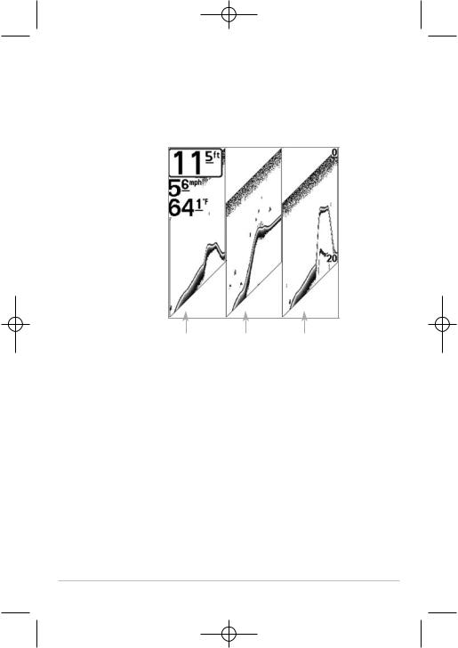
The sonar returns from the bottom, structure and fish can be represented as either Inverse (default), WhiteLine®, Structure ID®, or Bottom Black. See
Sonar X-Press™ Menu: Bottom View for details on how to set the bottom view.
13
531524-1_A - 717 & 727 Man_Eng.qxp 9/30/2006 7:23 PM Page 19
Inverse is a method where weak returns are shown with dark pixels and strong returns with lighter pixels. This has the benefit of ensuring that weak signals will be clearly visible on the display.
Structure ID® represents weak returns as light pixels and strong returns as dark pixels. This has the benefit of ensuring that strong returns will be clearly visible on the display.
14

531524-1_A - 717 & 727 Man_Eng.qxp 9/30/2006 7:23 PM Page 20
WhiteLine® highlights the strongest sonar returns in white, resulting in a distinctive outline. This has the benefit of clearly defining the bottom on the display.
Bottom Black displays all pixels below the bottom contour as black, regardless of signal strength. This has the benefit of providing a high contrast between the bottom and other sonar returns on the display. Any targets such as fish, structure and thermoclines will be shown using the Structure ID® method.
15
531524-1_A - 717 & 727 Man_Eng.qxp 9/30/2006 7:23 PM Page 21
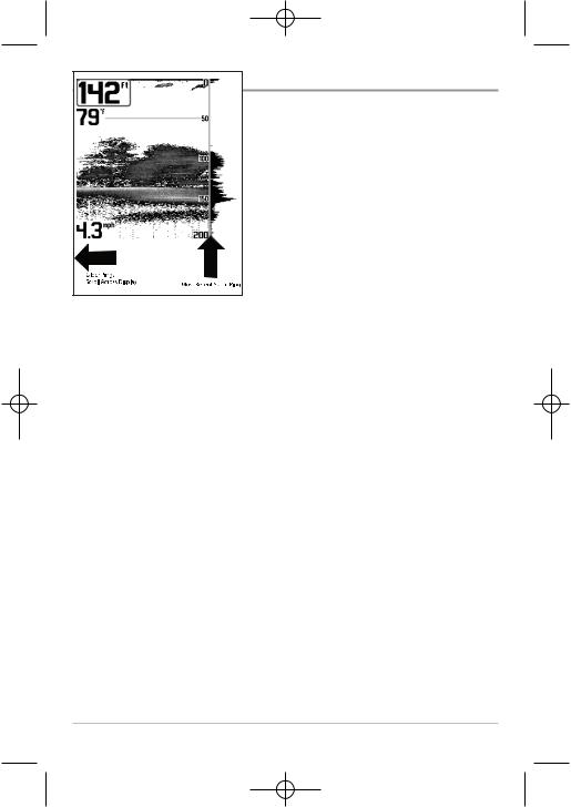
Sonar Zoom View
Sonar Zoom View increases the displayed resolution to separate sonar returns that are very close together, such as those caused by fish suspended close to the bottom or within structure. In Zoom View, the display is split to show a narrow slice of the full range view on the right and the zoomed view on the left. The full range view on the right also contains the Zoom Preview Box that shows what part of the full range view is shown in zoom view on the left; the Zoom Preview Box tracks the bottom in the full range view.
As the depth changes, the zoomed view updates automatically to display a magnified image of the bottom. The Zoom Preview Box shows where the zoomed view is in relation to the full range view. The Zoom Level, or magnification, is displayed in the lower left corner and can be changed to suit conditions (see Sonar X-Press™ Menu: Zoom Level). Upper and Lower Zoom Depth Range numbers indicate the depth of the water which is being viewed.
Digital depth is displayed in the upper left hand corner. The digital readouts in the Sonar Zoom View cannot be customized; therefore, information such as water temperature and voltage are unavailable in the Sonar Zoom View.
|
|
|
Sonar Zoom View |
||||
|
|
|
|
|
|
|
Upper Depth Range, |
|
|
|
|
|
|
|
|
Depth |
|
|
|
|
|
|
Full Range View |
|
|
|
|||||
|
|
|
|
|
|
|
Upper Depth Range, |
|
|
|
|
|
|
|
Zoom View |
|
|
|
|
|
|
|
Full Range |
|
|
|
|
|
|
|
View |
Zoomed |
|
|
|
|
Zoom |
||
|
|
|
|
||||
View |
|
|
|
|
Preview Box |
||
|
|
|
|
|
|
|
Lower Depth Range, |
|
|
|
|
|
|
|
Zoom View |
Zoom |
|
|
|
|
Lower Depth Range, |
||
Level |
|
|
|
|
Full Range View |
||
16

531524-1_A - 717 & 727 Man_Eng.qxp 9/30/2006 7:23 PM Page 22
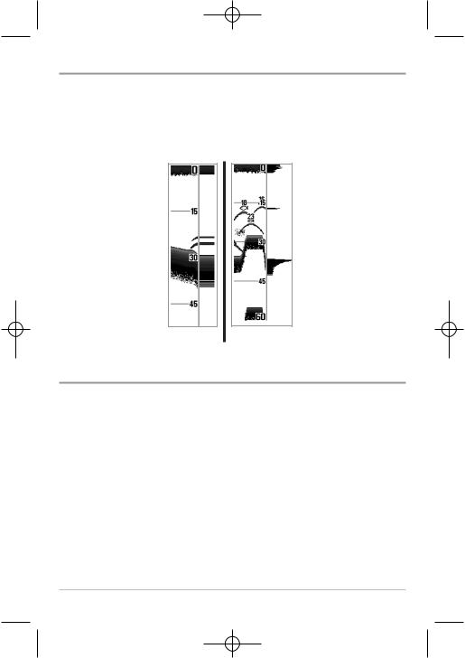
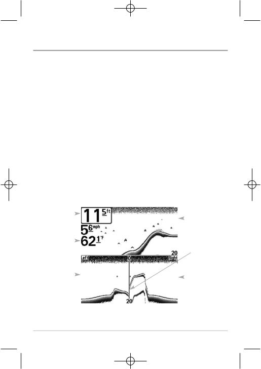
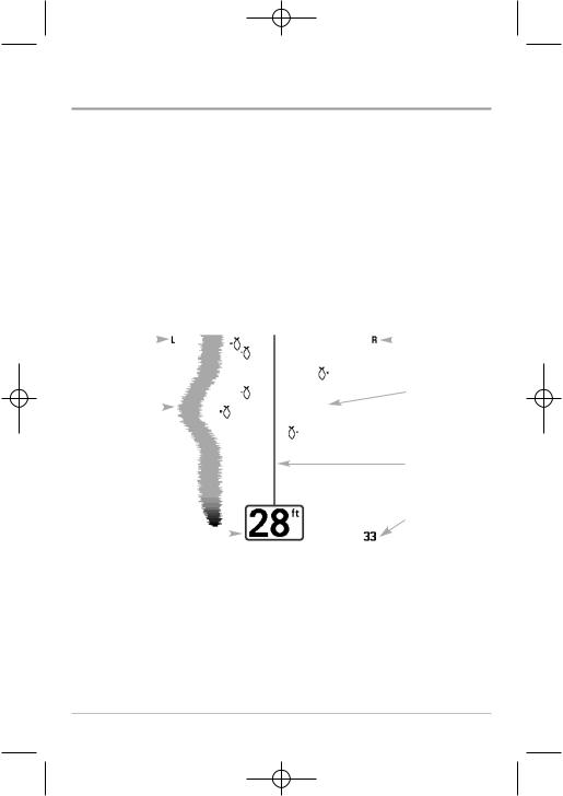
200/83 kHz Split Sonar View
Split Sonar View displays sonar returns from the 83 kHz wide beam on the left side of the screen and displays sonar returns from the 200 kHz narrow beam on the right side of the screen. Depth is always displayed in the upper left hand corner. You can use the Split Sonar View to make side by side comparisons between the sonar returns from the 83 kHz wide beam and the 200 kHz narrow beam.
The digital readouts in the Split Sonar View cannot be customized; therefore, information such as water temperature and voltage are unavailable in the Split Sonar View.
|
200/83 kHz Split Sonar View |
|
Upper Depth |
Depth |
Range |
|
200 kHz |
|
Sonar History |
|
Window |
83 kHz |
Lower Depth |
Sonar History |
|
Window |
Range |
17
531524-1_A - 717 & 727 Man_Eng.qxp 9/30/2006 7:23 PM Page 23
Big Digits View
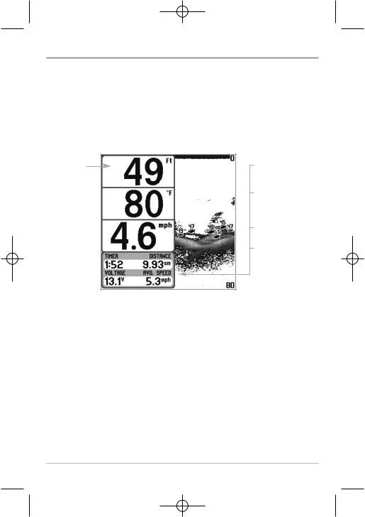
Big Digits View provides digital data in a large, easy-to-see format. Depth is always displayed. Readouts for temperature, speed and Triplog information are displayed automatically if the appropriate accessory is connected to the system. The Triplog shows distance traveled, average speed, and time elapsed since the Triplog was last reset. The digital readouts in the Big Digits View cannot be customized.
Big Digits View
Depth
Temperature 
Speed 
Timer shows the time elapsed since Triplog was last reset
Distance is the distance traveled since the Triplog was last reset
Voltage displays the battery voltage.
Average Speed shows the speed since the Triplog was last reset
18
531524-1_A - 717 & 727 Man_Eng.qxp 9/30/2006 7:23 PM Page 24
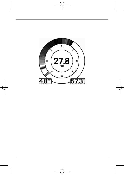
Circular Flasher View
Circular Flasher View displays Real Time Sonar (RTS®) data in the traditional flasher format. Depth and temperature are always displayed. The digital readouts in the Circular Flasher View cannot be customized.
19
531524-1_A - 717 & 727 Man_Eng.qxp 9/30/2006 7:23 PM Page 25
Side Beam View
(with optional-purchase QuadraBeam PLUS™ transducer)
Side Beam View is only available if you have connected an optional-purchase QuadraBeam PLUS™ transducer accessory and when Transducer Select is set to QuadraBeam (see Sonar Menu Tab: Transducer Select). The QuadraBeam PLUS™ transducer requires a separate purchase. This view shows sonar information from both the left and right 455 kHz beams and the 200 kHz downlooking beam in one view. You can customize the way the sonar data is displayed in the Side Beam View to suit your personal preferences. Depending on the layout selected from the Quad Layout Sonar X-Press™ menu (only available on the Sonar X-Press™ menu when in Side Beam View), the display will represent the same sonar data in one of the following three layouts: Default, Classic, and Slanted.
Default layout: The top portion of the display presents a historical log of sonar returns from the 200 kHz down-looking sonar beam. New information in the down beam panel scrolls from right to left. The bottom portion of the display presents a historical log of sonar returns from the 455 kHz rightand leftlooking sonar beams. New information in the side beam panels scrolls from the center out.
Side Beam View, Default Layout
Depth |
|
|
|
|
|
200 kHz |
|
|
|
|
|||
|
|
|
|
|
|
|
|
|
|
|
|
|
Sonar |
|
|
|
|
|
|
History |
|
|
|
|
|
|
Window |
Temperature |
|
|
|
|
|
Water Surface |
|
|
|
|
|||
|
|
|
|
|
|
|
|
|
|
|
|
|
Line for |
|
|
|
|
|
|
455 kHz Sonar |
|
|
|
|
|
|
History Windows |
Left Side 455 |
|
|
|
|
|
Right Side |
|
|
|
|
|||
kHz Sonar |
|
|
|
|||
|
|
|
455 kHz |
|||
History Window |
|
|
|
|||
|
|
|
Sonar |
|||
|
|
|
|
|
|
|
|
|
|
|
|
|
History |
|
|
|
|
|
|
Window |
|
|
|
|
|
|
|
20
531524-1_A - 717 & 727 Man_Eng.qxp 9/30/2006 7:23 PM Page 26
Classic layout: The top portion of the display presents a historical log of sonar returns from the 200 kHz down-looking sonar beam. New information in the down beam panel scrolls from right to left. The bottom portion of the display presents a historical log of sonar returns from the 455 kHz rightand leftlooking sonar beams. New information appears at the top, and scrolls down the display.
Side Beam View, Classic Layout
Depth |
|
|
|
|
|
200 kHz |
|
|
|
|
|||
|
|
|
|
|
|
|
|
|
|
|
|
|
Sonar |
|
|
|
|
|
|
History |
|
|
|
|
|
|
Window |
Temperature |
|
|
|
|
|
Water Surface Line |
|
|
|
|
|||
|
|
|
|
|
|
|
|
|
|
|
|
|
for 455 kHz |
|
|
|
|
|
|
Sonar History |
|
|
|
|
|
|
Windows |
Left Side 455 |
|
|
|
|
|
Right Side |
|
|
|
|
|||
kHz Sonar |
|
|
|
|||
|
|
|
455 kHz |
|||
History Window |
|
|
|
|||
|
|
|
Sonar |
|||
|
|
|
|
|
|
|
|
|
|
|
|
|
History |
|
|
|
|
|
|
Window |
|
|
|
|
|
|
|
21
531524-1_A - 717 & 727 Man_Eng.qxp 9/30/2006 7:23 PM Page 27
Slanted layout: This layout presents the two 455 kHz side sonar beams and the 200 kHz down-looking sonar beam as three panels of historical data. This layout is presented as three slanted panels. New information appears on the right, and scrolls to the left.
Side Beam View, Slanted Layout
Depth
Temperature
Left Side |
200 kHz Sonar |
Right Side |
455 kHz Sonar |
History Window |
455 kHz Sonar |
History Window |
|
History Window |
In all of these layouts, the sonar information from the side-looking beams reveals bottom contour, structure and fish similar to the down-looking beam, but the area covered is to the left and right of the area shown in the downlooking portion, so you actually see more of the bottom. The distance covered by the right and left beams is based on the depth setting for the down-looking beam, up to a maximum of 160 feet.
22
531524-1_A - 717 & 727 Man_Eng.qxp 9/30/2006 7:23 PM Page 28
WideSide® View
(with optional-purchase WideSide® transducer)
WideSide® View is only available if you have connected a WideSide® transducer accessory and when Transducer Select is set to WideSide® (see Sonar Menu Tab: Transducer Select). The WideSide® transducer requires a separate purchase. The WideSide® View displays information from the 455 kHz WideSide® transducer. Three views are available: Left, Right and Both. The default view is Both. Information from both the left and right beams are displayed simultaneously. The depth of the water beneath the boat is always displayed. A bottom contour may be present while bank fishing or fishing river channels. When fishing in the open water, a bottom contour will not be present, and only sonar returns from either debris or fish will be displayed.
|
|
|
|
|
WideSide View |
|||
Left Side |
|
|
|
|
|
|
|
Right Side View |
View |
|
|
|
|
|
|||
|
|
|
|
|
|
|
|
Open Water |
Bank |
|
|
|
|
|
|
(no bottom |
|
Contour |
|
|
|
|
contour visible |
|||
|
|
|
|
|
|
|
|
on-screen) |
|
|
|
|
|
|
|
|
Water |
|
|
|
|
|
|
|
|
Surface Line |
|
|
|
|
|
|
|
|
Side Beam |
Depth |
|
|
|
|
|
|
|
Depth Range |
|
|
|
|
|
|
|||
|
|
|
|
|
|
|
|
|
23
531524-1_A - 717 & 727 Man_Eng.qxp 9/30/2006 7:23 PM Page 29
Key Functions
Your Fishing System user interface consists of a set of easy-to-use keys that work with various on-screen views and menus to give you flexibility and control over your fishing experience.
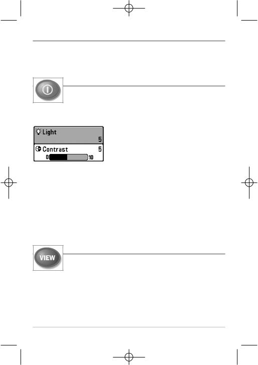
POWER/LIGHT Key
The POWER/LIGHT key is used to turn the Fishing System on and off, and also to adjust the backlight and contrast of the display.
Press the POWER/LIGHT key to turn the unit on. The Title screen is then displayed until the Fishing System begins sonar operation.
Your Fishing System will start up with the backlight on and will automatically turn it off to conserve power. To turn the backlight on for night fishing, or to adjust the display contrast, press the POWER/LIGHT key to access the Light and
Contrast menu. Use the 4-WAY Cursor key to select Light or Contrast and then use the LEFT or RIGHT Cursor key to change the settings. Press EXIT to exit the Light and Contrast menu.
Press and hold the POWER/LIGHT key for 3 seconds to turn the unit off. A message will appear telling you how many seconds there are until shutdown occurs. Your Fishing System should always be turned off using the POWER/LIGHT key. This will ensure that shutdown occurs properly and any menu settings will be saved.
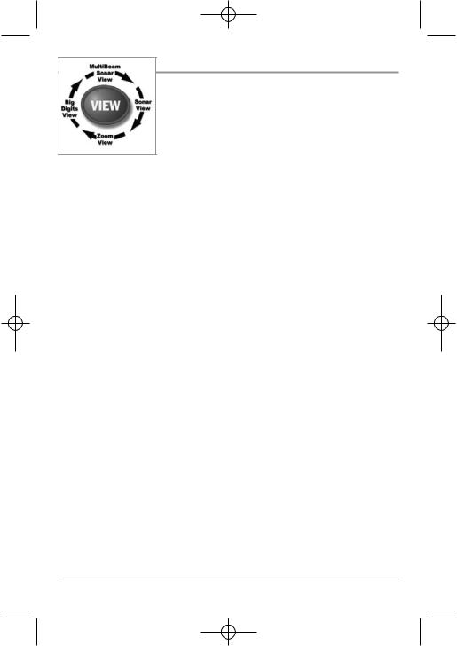
VIEW Key
The VIEW key is used to cycle through all available views. Press the VIEW key to advance to the next view. Repeatedly pressing VIEW cycles through all views available. Views can be hidden to optimize the system to your fishing requirements (see Views Menu Tab).
24
 Loading...