


HDR 650
531874-3_A
HDR 650 Installation
and Operations Manual
HDR 650 Installation
and Operations Manual

Thank You!
Thank you for choosing Humminbird®, America's #1 name in fishfinders.
Humminbird has built its reputation by designing and manufacturing
top-quality, thoroughly reliable marine equipment.
Your Humminbird is designed for trouble-free use in even the harshest marine
environment. In the unlikely event that your Humminbird does require repairs,
we offer an exclusive Service Policy. For complete details, see the separate
warranty card included with your unit.
Contact Humminbird Customer Service at 1-800-633-1468 or visit our Web site
at humminbird.com.
WARNING! This device should not be used as a navigational aid to prevent
collision, grounding, boat damage, or personal injury. When the boat is moving,
water depth may change too quickly to allow time for you to react. Always operate
the boat at very slow speeds if you suspect shallow water or submerged objects.
WARNING! Disassembly and repair of this electronic unit should only be
performed by authorized service personnel. Any modification of the serial number
or attempt to repair the original equipment or accessories by unauthorized
individuals will void the warranty.
NOTE: The procedures and features described in this manual are subject to change
without notice. This manual was written in English and may have been translated
to another language. Humminbird is not responsible for incorrect translations or
discrepancies between documents.
Humminbird® is a registered trademark of Johnson Outdoors Marine Electronics, Inc.
© 2018 Johnson Outdoors Marine Electronics, Inc. All rights reserved.

Table of Contents
i
How Sonar Works 1
Installation Overview 2
Installing the HDR 650 .................................................................................................... 3
1. Locating the HRD 650 Mounting Position ............................................................ 4
2. Cutting the Mounting Hole .................................................................................... 4
3. Customizing and Assembling the HDR 650 .......................................................... 5
4. Installing the HDR 650 .......................................................................................... 6
5. Installing the Buzzer................................................................................................ 7
6. Connecting to the Power Supply............................................................................ 7
7. Installing the Transducer ........................................................................................ 8
8. Connecting the Transducer Cable.......................................................................... 9
9. Testing and Finishing the Installation.................................................................... 9
Operating the HDR 650 10
The HDR 650 Control Head............................................................................................ 10
Power On/Off.................................................................................................................. 11
Key Functions Overview ................................................................................................ 11
Units................................................................................................................................ 12
Shallow Alarm ................................................................................................................ 13
Deep Alarm .................................................................................................................... 14
Set Offset (waterline or keel) ........................................................................................ 15
Maintenance 16
HDR 650 Maintenance .................................................................................................. 16
Transducer Maintenance .............................................................................................. 16
Troubleshooting 17
HDR 650 Doesn't Power Up .......................................................................................... 17

Table of Contents
ii
No Bottom Reading on the Display .............................................................................. 18
No Continuous Depth Display in Very Shallow Water ................................................ 18
Screen Fades, Images are not Sharp............................................................................ 18
Bottom Reading Disappears During a Hard Turn ........................................................ 18
Specifications 19
Contact Humminbird 22
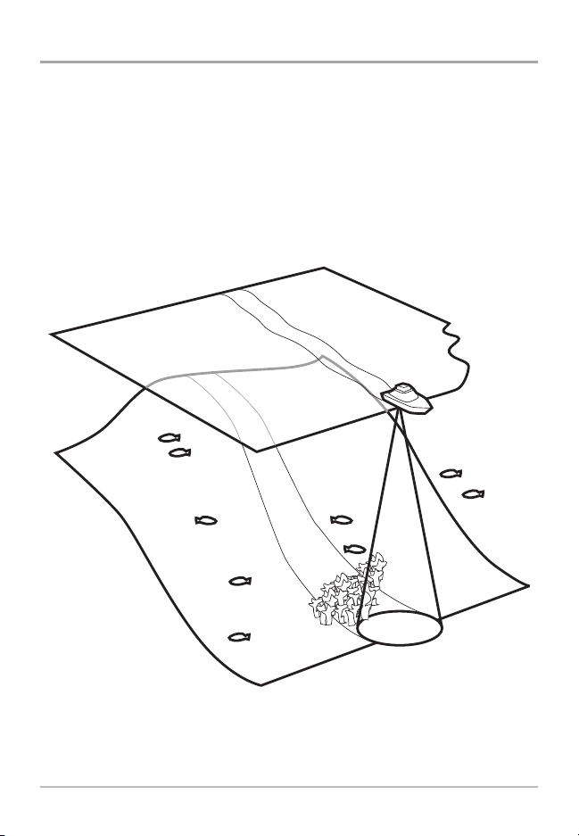
How Sonar Works
Sonar technology is based on sound waves. The HDR 650 Digital Depth Sounder
uses sonar to determine depth directly below the transducer. Your HDR 650
Digital Depth Sounder consists of two components: the HDR 650 sonar unit and
the transducer. The sonar unit contains the transmitter and receiver, as well as
the user controls and display. The transducer is mounted beneath the water
surface and converts electrical energy from the transmitter into mechanical
pulses or sound waves. The transducer also receives the reflected sound waves
and converts them back into electrical signals for display on the sonar unit.
Sonar is very fast. A sound wave can travel from the surface to a depth of 240 ft
(70 m) and back again in less than 1/4 of a second. It is unlikely that your boat
can "outrun" this sonar signal.
1
How Sonar Works

Installation Overview
Before you start installation, we encourage you to read these instructions
carefully in order to get the full benefit from your HDR 650 Digital Depth Sounder.
In addition to the hardware included in the installation kit, you will also
need the following supplies:
• powered hand drill and various drill bits, including a 2 1/8" hole saw if your
boat does not have an existing gauge hole
• Phillips-head and flat-head screwdrivers
• ruler or measuring tape
• pen or pencil
• 12 Volt power source (your boat's battery)
• marine-grade silicone sealant (for sealing drilled holes)
NOTE: If you are wiring directly to the boat's battery, you will also need a 1 Amp
fuse and a fuse holder.
2
Installation

Installing the HDR 650
You will install your HDR 650 depth sounder first, then your transducer. When
you are done with both of these installation tasks, you should perform a final
installation test before operating your HDR 650. Perform the following high-level
steps by following the instructions in each numbered section to install the depth
sounder:
1. Locating the HRD 650 mounting position
2. Cutting the mounting hole
3. Customizing and assembling the HDR 650
4. Installing the HDR 650
5. Installing the buzzer
6. Connecting to the power supply
7. Installing the transducer: See the transducer installation guide included
with your product.
8. Connecting the transducer cable
9. Testing and finishing the installation
3
Installation

1. Locating the HDR 650 Mounting Position
You must select an appropriate mounting location for the HDR 650. Consider
different positions on the console or deck of the boat, and note the following:
• The cables for the transducer and power must reach the mounting location.
Extension cables are available.
• The mounting surface should be visible to the boat operator and adequately
supported to protect the HDR 650 from excessive wave shock and vibration.
• Allow at least 2" clearance at the back, sides, and top of the unit for
connection, air flow, and ease of installation and removal.
2. Cutting the Mounting Hole
Once you have selected your mounting location, perform the following steps:
1. Mark the desired mounting location, then drill a pilot hole.
2. Drill a 2 1/8" diameter hole using a hole saw and hand drill. This is a
standard hole saw readily availablefor rental or purchase. If you prefer, any
marine service shop can perform this task.
Choosing Mounting Hole Location
4
Installation
 Loading...