


 Loading...
622 Mb/s Logic Interface DFB
Laser Transmitter
Preliminary Technical Data
Features
•SONET/SDH Compliant to
STM4 L-4.1 OC12 LR-1
•–40°C to +85°C Operation
•Compact 20 Pin Package
•ECL/PECL Logic Interface
•Multisourced Pinout
Applications
•SONET/SDH Systems
•Fiber to the Home
•Data Communications Networks
Description
The XMT5170-622 is a high performance uncooled optical DFB laser transmitter for CCITT SDH and ANSI SONET applications. It is designed with
XMT5170-622
an ECL/PECL logic interface for 622 MBd transmission.
The transmitter incorporates several features which simplify system design. The XMT5170-622 may be operated with either +5 V or –5 V power supplies. Its standard 10 KH ECL data interface enables direct interface with PECL or ECL logic. The compact transmitter module contains a pigtailed laser, data interface, bias and modulation control circuitry. Thus, no external components or adjustments are necessary. Finally, a laser disable input is provided to shut down the laser for standby or test purposes.
The XMT5170-622 includes analog outputs which are
proportional to laser current and optical power. These may be used with external circuitry to detect end-of-life, or over temperature conditions.
The transmitter is packaged in a 20 pin 0.4" pitch DIP. Contact your local representative for more details.
Preliminary Product Disclaimer
This preliminary data sheet is provided to assist you in the evaluation of engineering samples of the product which is under development and targeted for release during 1997. Until Hewlett-Packard releases this product for general sales, HP reserves the right to alter prices, specifications, features, capabilities, function, manufacturing release dates, and even general availability of the product at any time.
430 |
(5/97) |
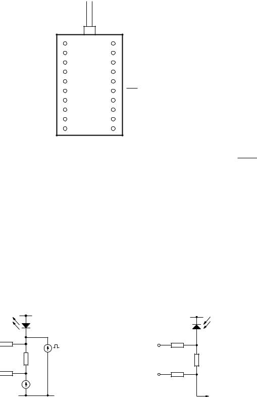
Connection Diagram
Top View
FIBER PIGTAIL
NC |
1 |
20 |
NC |
LASER BIAS MONITOR (+) |
2 |
19 |
LASER BACK FACET MONITOR (+) |
NC |
3 |
18 |
VCC |
LASER BIAS MONITOR (–) |
4 |
17 |
LASER BACK FACET MONITOR (–) |
VEE |
5 |
16 |
DATA |
VCC |
6 |
15 |
DATA |
TRANSMIT DISABLE |
7 |
14 |
VEE |
VCC |
8 |
13 |
CASE GROUND (SEE NOTE BELOW) |
VCC |
9 |
12 |
VCC |
NC |
10 |
11 |
CASE GROUND (SEE NOTE BELOW) |
Pin Descriptions
Pins 1, 3, 10, 20, NC:
These pins should not be connected and should be left open circuit on the application PCB.
Pin 2, Laser Bias Monitor (+):
See Figure 1.
Pins 6, 8, 9, 12, 18, VCC: |
Pins 15, 16, DATA, DATA: |
These pins are connected to +5 V |
These are differential ECL inputs. |
for positive supply systems and |
If open circuited they float to VBB |
ground for –5.2 V systems. |
(VCC –1.3 V). |
Pin 7, Transmit Disable: |
Pin 17, Laser Back Facet |
Pin 7 floats to VEE when open |
Monitor (–): |
circuited, enabling the |
See Figure 2. |
transmitter. It must be biased |
|
Pin 4, Laser Bias Monitor (–):
See Figure 1.
Pins 5, 14, VEE:
These pins are connected to ground in +5 V systems and –5 V in negative supply systems.
within 3 V of VCC to disable. |
Pin 19, Laser Back Facet |
|
Monitor (+): |
Pins 11, 13, Ground: |
See Figure 2. |
The XMT5170-622 case is plastic, |
|
therefore pins are not connected. |
|
3 kΩ
PIN 2 

3 kΩ
PIN 4 

VCC |
V |
|
CC |
LASER |
|
MONITOR |
|
|
PHOTODIODE |
|
|
3 kΩ |
|
|
PIN 19 |
10 Ω |
MODULATION |
200 Ω |
CURRENT |
||
|
|
3 kΩ |
|
|
PIN 17 |
IBIAS
VEE |
TO LASER BIAS |
CONTROL CIRCUITRY |
Figure 1. Laser Bias Monitor Circuitry. |
Figure 2. Back Facet Monitor Circuitry. |
431
Loading...