


 Loading...
HP PageWide Enterprise Color 765, PageWide Enterprise Color 780, PageWide Enterprise Color 785 Troubleshooting Manual
HP PageWide Enterprise Color 765 and MFP 780/785
HP PageWide Managed Color E75160 and MFP E77650/P77660
Troubleshooting Manual
Copyright and License
© Copyright 2017 HP Development Company,
L.P.
Reproduction, adaptation, or translation without prior written permission is prohibited, except as allowed under the copyright laws.
The information contained herein is subject to change without notice.
The only warranties for HP products and services are set forth in the express warranty statements accompanying such products and services. Nothing herein should be construed as constituting an additional warranty. HP shall not be liable for technical or editorial errors or omissions contained herein.
Edition 1, 9/2017
Trademark Credits
Microsoft®, Windows®, Windows® XP, and Windows Vista® are U.S. registered trademarks of Microsoft Corporation.
Adobe®, Acrobat®, and PostScript® are trademarks of Adobe Systems Incorporated.
UNIX® is a registered trademark of The Open Group.

Conventions used in this guide
TIP: Helpful hints or shortcuts.
 NOTE: Information that explains a concept or how to complete a task.
Reinstallation tip: Reinstallation helpful hints, shortcuts, or considerations.
 IMPORTANT: Information that help the user to avoid potential printer error conditions.
 CAUTION: Procedures that the user must follow to avoid losing data or damaging the printer.
WARNING! Procedures that the user must follow to avoid personal injury, catastrophic loss of data, or extensive damage to the printer.
ENWW |
iii |
iv |
Conventions used in this guide |
ENWW |

For additional service and support information
HP service personnel, go to one of the following Web-based Interactive Search Engines (WISE) sites:
AMS
●https://support.hp.com/wise/home/ams-en
●https://support.hp.com/wise/home/ams-es
●https://support.hp.com/wise/home/ams-pt
APJ
●https://support.hp.com/wise/home/apj-en
●https://support.hp.com/wise/home/apj-ja
●https://support.hp.com/wise/home/apj-ko
●https://support.hp.com/wise/home/apj-zh-Hans
●https://support.hp.com/wise/home/apj-zh-Hant
EMEA
●https://support.hp.com/wise/home/emea-en
Channel partners, go to HP Channel Services Network (CSN) at www.hp.com/partners/csn .
At these locations, nd information on the following topics:
●Install and con gure
●Printer speci cations
●Up-to-date control panel message (CPMD) troubleshooting
●Solutions for printer issues and emerging issues
●Remove and replace part instructions and videos
●Service advisories
●Warranty and regulatory information
Channel partners, access training materials in the HP University and Partner Learning Center at https://content.ext.hp.com/sites/LMS/HPU.page.
To access HP PartSurfer information from any mobile device, go to http://partsurfermobile.hp.com/ or scan the Quick Response (QR) code below.
ENWW |
v |
vi |
For additional service and support information |
ENWW |

Table of contents
1 Theory of operation .................................................................................................................................................................................. |
1 |
Basic operation ......................................................................................................................................................................... |
2 |
Function structure ............................................................................................................................................... |
2 |
Operation sequence ............................................................................................................................................ |
4 |
System control .......................................................................................................................................................................... |
6 |
................................................................................................................................................................................. |
6 |
Formatter and data path .................................................................................................................................... |
6 |
Engine control ...................................................................................................................................................... |
8 |
Pen interface (I/F) .............................................................................................................................................. |
10 |
Power supply ...................................................................................................................................................... |
11 |
AC control module ............................................................................................................................................. |
11 |
Cabling system ....................................................................................................................................................................... |
13 |
Flat Flexible Cables ........................................................................................................................................... |
13 |
FFC routing .......................................................................................................................................................... |
16 |
Discrete cables ................................................................................................................................................... |
19 |
Ground wires ...................................................................................................................................................... |
20 |
Connectors .......................................................................................................................................................... |
21 |
Ferrites ................................................................................................................................................................ |
23 |
Cable management ........................................................................................................................................... |
23 |
Print subsystem ..................................................................................................................................................................... |
25 |
Printhead ............................................................................................................................................................ |
25 |
Printhead air management system ................................................................................................................ |
26 |
Printhead lift ....................................................................................................................................................... |
26 |
Print cartridges .................................................................................................................................................. |
26 |
Optical scan carriage ......................................................................................................................................... |
26 |
Print system operational states ...................................................................................................................... |
26 |
Paper-handling system ......................................................................................................................................................... |
29 |
Printer sensors ................................................................................................................................................... |
29 |
High Capacity Input (HCI) sensors ................................................................................................................... |
30 |
3x550 tray sensors ........................................................................................................................................... |
31 |
1x550 tray sensors ........................................................................................................................................... |
32 |
Inline nisher sensors ....................................................................................................................................... |
33 |
ENWW |
vii |
Printer motors/solenoids ................................................................................................................................. |
34 |
High capacity input (HCI) motors/solenoids .................................................................................................. |
35 |
3x550 tray motors/solenoids .......................................................................................................................... |
36 |
1x550 tray motors/solenoids .......................................................................................................................... |
37 |
Inline nisher motors ........................................................................................................................................ |
38 |
Printer printing system ..................................................................................................................................... |
39 |
Input trays ........................................................................................................................................................... |
40 |
Paper path zones ............................................................................................................................................... |
43 |
Jam detection ..................................................................................................................................................... |
45 |
Servicing system .................................................................................................................................................................... |
48 |
Printhead wiper .................................................................................................................................................. |
48 |
Service fluid and aerosol management systems ............................................................................................................. |
49 |
irflow system ........................................................................................................................................................................ |
51 |
Function .............................................................................................................................................................. |
51 |
Heating ................................................................................................................................................................ |
51 |
irflow ................................................................................................................................................................. |
51 |
Modes .................................................................................................................................................................. |
51 |
Components ....................................................................................................................................................... |
52 |
Document feeder system ..................................................................................................................................................... |
53 |
Document feed system .................................................................................................................................... |
53 |
Sensors in the document feeder .................................................................................................................... |
53 |
Document feeder paper path .......................................................................................................................... |
54 |
Document feeder simplex operation ............................................................................................................. |
55 |
Document feeder e-duplex operation ........................................................................................................... |
56 |
Deskew operation ............................................................................................................................................. |
57 |
Document feeder hinges .................................................................................................................................. |
57 |
Scanning and image capture system (780/785) .............................................................................................................. |
59 |
Fax functions and operation ................................................................................................................................................. |
60 |
Computer and network security features ..................................................................................................... |
60 |
PSTN operation .................................................................................................................................................. |
60 |
The fax subsystem ............................................................................................................................................ |
60 |
Fax card in the fax subsystem ......................................................................................................................... |
60 |
Fax page storage in flash memory ................................................................................................................. |
62 |
Output accessories ................................................................................................................................................................ |
63 |
Inline nisher ...................................................................................................................................................... |
64 |
2 Solve problems ....................................................................................................................................................................................... |
91 |
Problem-solving checklist .................................................................................................................................................... |
92 |
Step 1: Check that the printer power is on .................................................................................................... |
92 |
Step 2: Check the control panel for error messages ................................................................................... |
92 |
Step 3: Test print functionality ........................................................................................................................ |
93 |
viii |
ENWW |
Step 4: Test copy functionality (MFP models only) ...................................................................................... |
93 |
Step 5: Test the fax sending functionality (785f/785zs/785z+) ............................................................... |
94 |
Step 6: Test the fax receiving functionality (fax models only) ................................................................... |
94 |
Step 7: Try sending a print job from a computer ......................................................................................... |
94 |
Step 8: Test the Plug and Print USB Drive printing functionality ............................................................... |
94 |
Factors that a ect printer performance ........................................................................................................ |
94 |
Troubleshooting process ...................................................................................................................................................... |
96 |
Determine the problem source ....................................................................................................................... |
96 |
Power subsystem .............................................................................................................................................. |
98 |
Tools for troubleshooting ................................................................................................................................................... |
129 |
Print the con guration and printhead information pages ........................................................................ |
129 |
Event log messages ........................................................................................................................................ |
132 |
Tools for troubleshooting: Individual component diagnostics ................................................................ |
133 |
Diagrams .......................................................................................................................................................... |
146 |
Print-quality troubleshooting tools .............................................................................................................. |
159 |
Control panel menus ...................................................................................................................................... |
168 |
Control panel message document (CPMD) ................................................................................................. |
243 |
Print quality troubleshooting guide .................................................................................................................................. |
244 |
Printer pre-checks .......................................................................................................................................... |
244 |
Printer speci c image defects ....................................................................................................................... |
258 |
Solve copy/scan problems (780/785) .............................................................................................................................. |
297 |
Solve copy problems (780/785 models only) ............................................................................................ |
297 |
Solve scan problems (780/785 models only) ............................................................................................ |
302 |
Solve paper jam or feed problems ................................................................................................................................... |
308 |
Printer does not pick up paper or misfeeds ................................................................................................ |
308 |
Clear paper jams ............................................................................................................................................. |
310 |
Solve performance problems ............................................................................................................................................ |
340 |
Factors a ecting print performance ............................................................................................................ |
340 |
The printer does not print or it prints slowly .............................................................................................. |
341 |
The printer prints slowly ................................................................................................................................ |
342 |
Solve connectivity problems .............................................................................................................................................. |
343 |
Solve USB connection problems ................................................................................................................... |
343 |
Solve wired network problems ..................................................................................................................... |
343 |
Service mode functions ...................................................................................................................................................... |
345 |
Service menu ................................................................................................................................................... |
345 |
Printer resets ................................................................................................................................................... |
354 |
Format Disk and Partial Clean functions ..................................................................................................... |
356 |
Firmware upgrades ............................................................................................................................................................. |
359 |
Determine the installed revision of rmware ............................................................................................. |
359 |
Perform a rmware upgrade ........................................................................................................................ |
361 |
Solve fax problems .............................................................................................................................................................. |
365 |
ENWW |
ix |
Solve email problems ......................................................................................................................................................... |
366 |
Appendix A Printer speci cations ......................................................................................................................................................... |
367 |
Printer dimensions and weight ......................................................................................................................................... |
368 |
Printer space requirements ............................................................................................................................................... |
369 |
Power consumption, electrical speci cations, and acoustic emissions ...................................................................... |
369 |
Operating-environment range .......................................................................................................................................... |
370 |
Certi cate of Volatility ......................................................................................................................................................... |
371 |
Index ........................................................................................................................................................................................................... |
415 |
x |
ENWW |
List of tables
Table 1-1 |
Operation sequence ................................................................................................................................................................ |
4 |
Table 1-2 |
Printbar components ............................................................................................................................................................ |
25 |
Table 1-3 Service Fluid and Aerosol Management System Components ...................................................................................... |
50 |
|
Table 1-4 Document feeder sensors ................................................................................................................................................... |
54 |
|
Table 1-5 Document feeder paper path .............................................................................................................................................. |
54 |
|
Table 2-1 |
Troubleshooting flowchart .................................................................................................................................................. |
97 |
Table 2-2 |
MPCA LEDs ........................................................................................................................................................................... |
100 |
Table 2-3 MPCA LED sequence at printer power on ....................................................................................................................... |
100 |
|
Table 2-4 |
MPCA LEDs ........................................................................................................................................................................... |
133 |
Table 2-5 MPCA LED sequence at printer power on ....................................................................................................................... |
134 |
|
Table 2-6 |
ACCM LEDs ........................................................................................................................................................................... |
135 |
Table 2-7 ACCMA LED sequence at printer power on ..................................................................................................................... |
135 |
|
Table 2-8 Heartbeat LED, product initialization ............................................................................................................................... |
136 |
|
Table 2-9 Heartbeat LED, product operational ................................................................................................................................ |
139 |
|
Table 2-10 |
Reports menu ................................................................................................................................................................... |
169 |
Table 2-11 |
Settings menu ................................................................................................................................................................... |
171 |
Table 2-12 Copy menu (MFP only) ..................................................................................................................................................... |
197 |
|
Table 2-13 Scan menu (780/785) ..................................................................................................................................................... |
203 |
|
Table 2-14 Fax menu (fax models only) ........................................................................................................................................... |
231 |
|
Table 2-15 Print Options menu .......................................................................................................................................................... |
235 |
|
Table 2-16 |
Supplies menu .................................................................................................................................................................. |
236 |
Table 2-17 |
Trays menu ........................................................................................................................................................................ |
237 |
Table 2-18 |
Backup/Restore menu ..................................................................................................................................................... |
238 |
Table 2-19 |
Calibrate/Cleaning menu ................................................................................................................................................. |
238 |
Table 2-20 |
Troubleshooting menu .................................................................................................................................................... |
240 |
Table 2-21 Printhead health score .................................................................................................................................................... |
251 |
|
Table 2-22 Solve performance problems ......................................................................................................................................... |
340 |
|
Table 2-23 |
Service menu .................................................................................................................................................................... |
345 |
Table A-1 Dimensions for printer base model (SFP; all) ................................................................................................................. |
368 |
|
Table A-2 Dimensions for base models (780dn, 785f; MFP) ......................................................................................................... |
368 |
|
Table A-3 Dimensions for 785zs (MFP) ............................................................................................................................................. |
368 |
|
Table A-4 Dimensions for the 1x550-sheet paper feeder ............................................................................................................. |
368 |
|
ENWW |
xi |
Table A-5 |
Dimensions for the 1x550-sheet paper feeder with stand ......................................................................................... |
369 |
Table A-6 |
Dimensions for the 3x550-sheet paper feeder with stand ......................................................................................... |
369 |
Table A-7 |
Dimensions for the 4,000-sheet HCI with stand ........................................................................................................... |
369 |
Table A-8 |
Operating-environment speci cations ............................................................................................................................ |
370 |
xii |
ENWW |

List of gures
Figure 1-3 FFC insertion line ................................................................................................................................................................. |
13 |
|
Figure 1-4 FFC support tape ................................................................................................................................................................. |
14 |
|
Figure 1-5 |
FFC label ................................................................................................................................................................................ |
14 |
Figure 1-6 FFC wing feature .................................................................................................................................................................. |
15 |
|
Figure 1-7 |
ZIF connector ........................................................................................................................................................................ |
15 |
Figure 1-8 FFC hook arm retainers ...................................................................................................................................................... |
16 |
|
Figure 1-9 FFC pill bump retainers ....................................................................................................................................................... |
17 |
|
Figure 1-10 FFC die-cut retainers ........................................................................................................................................................ |
18 |
|
Figure 1-11 FFC double-sided tape retainer ...................................................................................................................................... |
18 |
|
Figure 1-12 Discrete cable ferrite ........................................................................................................................................................ |
19 |
|
Figure 1-13 Discrete cable tie-wraps .................................................................................................................................................. |
20 |
|
Figure 1-14 |
Ground wires ...................................................................................................................................................................... |
21 |
Figure 1-16 FFC wing feature ............................................................................................................................................................... |
22 |
|
Figure 1-17 |
ZIF connector ..................................................................................................................................................................... |
23 |
Figure 1-18 |
FFC spacing ........................................................................................................................................................................ |
24 |
Figure 1-19 |
Printhead components ..................................................................................................................................................... |
25 |
Figure 1-20 Print engine sensors ......................................................................................................................................................... |
29 |
|
Figure 1-21 |
HCI sensors ........................................................................................................................................................................ |
30 |
Figure 1-22 3x550 Tray sensors .......................................................................................................................................................... |
31 |
|
Figure 1-23 1x550 tray sensors ........................................................................................................................................................... |
32 |
|
Figure 1-24 |
Inline nisher sensors ....................................................................................................................................................... |
33 |
Figure 1-25 |
HCI motors/solenoids ....................................................................................................................................................... |
35 |
Figure 1-26 3x550 tray motors/solenoids ......................................................................................................................................... |
36 |
|
Figure 1-27 1x550 tray motors/solenoids ......................................................................................................................................... |
37 |
|
Figure 1-28 |
Inline nisher motors ........................................................................................................................................................ |
38 |
Figure 1-29 Printer printing system .................................................................................................................................................... |
39 |
|
Figure 1-30 Tray 1 pick and separation system ................................................................................................................................ |
40 |
|
Figure 1-31 Service fluid and aerosol management system .......................................................................................................... |
50 |
|
Figure 1-32 irflow system components ........................................................................................................................................... |
52 |
|
Figure 1-33 Document feeder sensors ............................................................................................................................................... |
54 |
|
Figure 1-34 Document feeder paper path .......................................................................................................................................... |
54 |
|
Figure 1-35 |
Deskew operation ............................................................................................................................................................. |
57 |
ENWW |
xiii |
Figure 1-36 Document feeder open (book mode) ............................................................................................................................ |
58 |
||
Figure 1-37 Document feeder open (60º to 80º) .............................................................................................................................. |
58 |
||
Figure 1-38 FFC insertion line ............................................................................................................................................................... |
67 |
||
Figure 1-39 FFC support tape ............................................................................................................................................................... |
68 |
||
Figure 1-40 |
FFC label ............................................................................................................................................................................. |
68 |
|
Figure 1-41 FFC hook arm retainers .................................................................................................................................................... |
69 |
||
Figure 1-42 FFC pill bump retainers .................................................................................................................................................... |
70 |
||
Figure 1-43 FFC die-cut retainers ........................................................................................................................................................ |
71 |
||
Figure 1-44 FFC double-sided tape retainer ...................................................................................................................................... |
71 |
||
Figure 1-45 Discrete cable ferrite ........................................................................................................................................................ |
72 |
||
Figure 1-46 Discrete cable tie-wraps .................................................................................................................................................. |
73 |
||
Figure 1-47 |
Connectors ......................................................................................................................................................................... |
74 |
|
Figure 1-48 |
FFC spacing ........................................................................................................................................................................ |
75 |
|
Figure 1-49 |
Inline |
nisher control diagram (front) ............................................................................................................................ |
76 |
Figure 1-50 |
Inline |
nisher sensor control diagram (front) ............................................................................................................... |
77 |
Figure 1-51 |
Inline |
nisher motor control diagram (front) ................................................................................................................ |
78 |
Figure 1-52 |
Inline |
nisher sensor diagram (1 of 2) ........................................................................................................................... |
79 |
Figure 1-53 |
Inline |
nisher sensor diagram (2 of 2) ........................................................................................................................... |
80 |
Figure 1-54 |
Inline |
nisher motor diagram .......................................................................................................................................... |
81 |
Figure 1-55 |
Inline |
nisher stapler control diagram ........................................................................................................................... |
82 |
Figure 1-56 |
Inline |
nisher stapler sensor diagram ........................................................................................................................... |
83 |
Figure 1-57 |
Inline |
nisher stapler motor control diagram ............................................................................................................... |
84 |
Figure 2-1 |
MPCA LEDs ......................................................................................................................................................................... |
100 |
|
Figure 2-2 Formatter heartbeat LED ................................................................................................................................................. |
101 |
||
Figure 2-3 Diagnostic-tests access button (765 printers) ............................................................................................................. |
104 |
||
Figure 2-4 Diagnostic-tests access button (780/785 printers) .................................................................................................... |
104 |
||
Figure 2-5 Press the diagnostics-access button (780/785 printers) ........................................................................................... |
105 |
||
Figure 2-6 Control panel version A yellow screen ........................................................................................................................... |
105 |
||
Figure 2-7 Exit the diagnostic mode ................................................................................................................................................. |
107 |
||
Figure 2-8 Open the Pre-boot menu ................................................................................................................................................. |
108 |
||
Figure 2-9 |
Pre-boot menu .................................................................................................................................................................. |
109 |
|
Figure 2-10 Access the administration menu .................................................................................................................................. |
110 |
||
Figure 2-11 Access the diagnostics menu ........................................................................................................................................ |
110 |
||
Figure 2-12 Open the screen test ...................................................................................................................................................... |
111 |
||
Figure 2-13 Blue vertical gradient screen ........................................................................................................................................ |
111 |
||
Figure 2-14 Open the touch test ........................................................................................................................................................ |
115 |
||
Figure 2-15 Touch the white grid ....................................................................................................................................................... |
115 |
||
Figure 2-16 Verify the mark ............................................................................................................................................................... |
116 |
||
Figure 2-17 Open the softkey test .................................................................................................................................................... |
117 |
||
Figure 2-18 |
Select Home .................................................................................................................................................................... |
117 |
|
Figure 2-19 |
Successful test ................................................................................................................................................................ |
118 |
|
xiv |
ENWW |
Figure 2-20 Open the backlight test .................................................................................................................................................. |
119 |
||
Figure 2-21 Open the sound test ....................................................................................................................................................... |
120 |
||
Figure 2-22 Open the keyboard test ................................................................................................................................................. |
121 |
||
Figure 2-23 Open the sound test ....................................................................................................................................................... |
122 |
||
Figure 2-24 Touchscreen blank, white, or dim (no image) ............................................................................................................ |
124 |
||
Figure 2-25 Touchscreen has an unresponsive zone ..................................................................................................................... |
125 |
||
Figure 2-26 No control panel sound .................................................................................................................................................. |
126 |
||
Figure 2-27 Home key is unresponsive ............................................................................................................................................ |
127 |
||
Figure 2-28 Hardware integration pocket (HIP) is not functioning (control panel functional) ................................................ |
128 |
||
Figure 2-29 |
Con guration page ......................................................................................................................................................... |
129 |
|
Figure 2-30 Printhead information page .......................................................................................................................................... |
131 |
||
Figure 2-31 |
MPCA LEDs ....................................................................................................................................................................... |
133 |
|
Figure 2-32 |
ACCM LEDs ....................................................................................................................................................................... |
135 |
|
Figure 2-33 Defeating interlocks (cartridge door) .......................................................................................................................... |
141 |
||
Figure 2-34 Defeating interlocks (left door) .................................................................................................................................... |
142 |
||
Figure 2-35 Defeating interlocks (right door) .................................................................................................................................. |
142 |
||
Figure 2-36 Plug/jack locations (external printer) .......................................................................................................................... |
146 |
||
Figure 2-37 Print engine sensors ...................................................................................................................................................... |
148 |
||
Figure 2-38 |
HCI sensors ...................................................................................................................................................................... |
149 |
|
Figure 2-39 3x550 tray sensors ........................................................................................................................................................ |
150 |
||
Figure 2-40 1x550 tray sensors ........................................................................................................................................................ |
151 |
||
Figure 2-41 |
Inline nisher sensors .................................................................................................................................................... |
152 |
|
Figure 2-42 |
Printer motors/solenoids .............................................................................................................................................. |
153 |
|
Figure 2-43 |
HCI motors/solenoids ..................................................................................................................................................... |
154 |
|
Figure 2-44 3x550 tray motors/solenoids ....................................................................................................................................... |
155 |
||
Figure 2-45 1x550 tray motors/solenoids ....................................................................................................................................... |
156 |
||
Figure 2-46 |
Inline nisher motors ..................................................................................................................................................... |
157 |
|
Figure 2-47 Printer printing system .................................................................................................................................................. |
158 |
||
Figure 2-50 |
Ink smear/redeposit ....................................................................................................................................................... |
255 |
|
Figure 2-51 Print Quality Report page .............................................................................................................................................. |
260 |
||
Figure 2-52 Print Head Diagnostic Page ........................................................................................................................................... |
262 |
||
Figure 2-53 Printhead Details page .................................................................................................................................................. |
264 |
||
Figure 2-67 Paper jam locations (765) ............................................................................................................................................. |
310 |
||
Figure 2-68 Paper jam locations (780/785) .................................................................................................................................... |
312 |
||
Figure 2-69 Open the Pre-boot menu .............................................................................................................................................. |
355 |
||
Figure 2-70 Open the Pre-boot menu .............................................................................................................................................. |
357 |
||
Figure 2-71 Open the Pre-boot menu .............................................................................................................................................. |
358 |
||
Figure 2-72 |
Determine the installed revision of rmware ............................................................................................................ |
360 |
|
Figure 2-73 Open the Pre-boot menu .............................................................................................................................................. |
363 |
||
Figure A-1 |
Certi |
cate of Volatility (750dn; 1 of 3) ........................................................................................................................... |
371 |
Figure A-2 |
Certi |
cate of Volatility (750dn; 2 of 3) ........................................................................................................................... |
372 |
ENWW |
xv |
Figure A-3 |
Certi |
cate of Volatility (750dn; 3 of 3) ........................................................................................................................... |
373 |
|
Figure A-4 |
Certi |
cate of Volatility (750dw; 1 of 4) .......................................................................................................................... |
374 |
|
Figure A-5 |
Certi |
cate of Volatility (750dw; 2 of 4) .......................................................................................................................... |
375 |
|
Figure A-6 |
Certi |
cate of Volatility (750dw; 3 of 4) .......................................................................................................................... |
376 |
|
Figure A-7 |
Certi |
cate of Volatility (750dw; 4 of 4) .......................................................................................................................... |
377 |
|
Figure A-8 |
Certi |
cate of Volatility (772dn; 1 of 3) ........................................................................................................................... |
378 |
|
Figure A-9 |
Certi |
cate of Volatility (772dn; 2 of 3) ........................................................................................................................... |
379 |
|
Figure A-10 |
Certi |
cate of Volatility (772dn; 3 of 3) ........................................................................................................................ |
380 |
|
Figure A-11 |
Certi |
cate of Volatility (772dw; 1 of 4) ........................................................................................................................ |
381 |
|
Figure A-12 |
Certi |
cate of Volatility (772dw; 2 of 4) ........................................................................................................................ |
382 |
|
Figure A-13 |
Certi |
cate of Volatility (772dw; 3 of 4) ........................................................................................................................ |
383 |
|
Figure A-14 |
Certi |
cate of Volatility (772dw; 4 of 4) ........................................................................................................................ |
384 |
|
Figure A-15 |
Certi |
cate of Volatility (777z; 1 of 4) ........................................................................................................................... |
385 |
|
Figure A-16 |
Certi |
cate of Volatility (777z; 2 of 4) ........................................................................................................................... |
386 |
|
Figure A-17 |
Certi |
cate of Volatility (777z; 3 of 4) ........................................................................................................................... |
387 |
|
Figure A-18 |
Certi |
cate of Volatility (777z; 4 of 4) ........................................................................................................................... |
388 |
|
Figure A-19 |
Certi |
cate of Volatility (75050dn; 1 of 3) .................................................................................................................... |
389 |
|
Figure A-20 |
Certi |
cate of Volatility (75050dn; 2 of 3) .................................................................................................................... |
390 |
|
Figure A-21 |
Certi |
cate of Volatility (75050dn; 3 of 3) .................................................................................................................... |
391 |
|
Figure A-22 |
Certi |
cate of Volatility (75050dw; 1 of 4) ................................................................................................................... |
392 |
|
Figure A-23 |
Certi |
cate of Volatility (75050dw; 2 of 4) ................................................................................................................... |
393 |
|
Figure A-24 |
Certi |
cate of Volatility (75050dw; 3 of 4) ................................................................................................................... |
394 |
|
Figure A-25 |
Certi |
cate of Volatility (75050dw; 4 of 4) ................................................................................................................... |
395 |
|
Figure A-26 |
Certi |
cate of Volatility (77740dn; 1 of 3) .................................................................................................................... |
396 |
|
Figure A-27 |
Certi |
cate of Volatility (77740dn; 2 of 3) .................................................................................................................... |
397 |
|
Figure A-28 |
Certi |
cate of Volatility (77740dn; 3 of 3) .................................................................................................................... |
398 |
|
Figure A-29 |
Certi |
cate of Volatility (77740dw; 1 of 4) ................................................................................................................... |
399 |
|
Figure A-30 |
Certi |
cate of Volatility (77740dw; 2 of 4) ................................................................................................................... |
400 |
|
Figure A-31 |
Certi |
cate of Volatility (77740dw; 3 of 4) ................................................................................................................... |
401 |
|
Figure A-32 |
Certi |
cate of Volatility (77740dw; 4 of 4) ................................................................................................................... |
402 |
|
Figure A-33 |
Certi |
cate of Volatility (77740z; 1 of 4) ...................................................................................................................... |
403 |
|
Figure A-34 |
Certi |
cate of Volatility (77740z; 2 of 4) ...................................................................................................................... |
404 |
|
Figure A-35 |
Certi |
cate of Volatility (77740z; 3 of 4) ...................................................................................................................... |
405 |
|
Figure A-36 |
Certi |
cate of Volatility (77740z; 4 of 4) ...................................................................................................................... |
406 |
|
Figure A-37 |
Certi |
cate of Volatility (77750z; 1 of 4) ...................................................................................................................... |
407 |
|
Figure A-38 |
Certi |
cate of Volatility (77750z; 2 of 4) ...................................................................................................................... |
408 |
|
Figure A-39 |
Certi |
cate of Volatility (77750z; 3 of 4) ...................................................................................................................... |
409 |
|
Figure A-40 |
Certi |
cate of Volatility (77750z; 4 of 4) ...................................................................................................................... |
410 |
|
Figure A-41 |
Certi |
cate of Volatility (77760z; 1 of 4) ...................................................................................................................... |
411 |
|
Figure A-42 |
Certi |
cate of Volatility (77760z; 2 of 4) ...................................................................................................................... |
412 |
|
Figure A-43 |
Certi |
cate of Volatility (77760z; 3 of 4) ...................................................................................................................... |
413 |
|
xvi |
ENWW |
Figure A-44 Certi cate of Volatility (77760z; 4 of 4) ...................................................................................................................... |
414 |
ENWW |
xvii |
xviii |
ENWW |

1Theory of operation
●Basic operation
●System control
●Cabling system
●Print subsystem
●Paper-handling system
●Servicing system
●Service fluid and aerosol management systems
●irflow system
●Document feeder system
●Scanning and image capture system (780/785)
●Fax functions and operation
●Output accessories
ENWW |
1 |

Basic operation
Function structure
HP recommends printing the following document (on A3 size paper) for troubleshooting reference. It is available on the HP Web-based Interactive Search Engines (WISE). See HP Web-based Interactive Search Engines (WISE) on page 3.
Figure 1-1 Printer printing system
Legend |
VentSolenoid |
S |
PumpFluid |
PumpFluidMotor |
|
N |
|
|
|
|
|
|
|
Motor
Fan/Digital Tach F
Solenoid N S
Opto Sensor
Reflective REDI
Other Sensors Pinch roller
Retard Roller Star Wheel
Switch/Hall
Effect Sensor
Torque Coupling
Media Path
12.13mm Dia
16.17mm Dia  PTO connection
150 LPI, 1200 Line
Digital Encoder
Acumen
Level Sensors |
|
Air Pump |
Fluid |
|
|
|
|
|
|
|
|
Printhead Assembly
Pinch 1
Ejection
|
Assembly |
F |
Motor |
|
|
AirflowFan |
|
Left Vertical Pinch 2 |
Airflow |
|
|
|
|
||
|
|
|
|
|
|
|
|
|
|
|
|
Image Sensor Carriage Motor |
|
|
|
Duplex Pinch 5 |
|
|
|
|
|
|
|
|
|
|
|
|
|
|
|
|
|
|
|
|
|
|
|
|
|
|
|
|
|
|
|
|
|
|
|
|
Air Pump Motor |
|
|
|
|
|
|
|
|
|
|
|
|
|
|
|
|
|
|
|
|
|
|
|
|
|
|
|
|
|
|
|
|
|
|
|
|
|
|
|
|
|
|
|
|
|
|
|
|
|
|
|
|
|
|
|
Printhead Wiper Motor |
|
|
|
Duplex |
Pinch 4 |
|
|
|
|
|
|
|
|
|
|
|
|
|
|
|
|
|
|
|
|
|
|
|
|
|
|
|
|
|
|
|
|
|
Printhead Lift |
Motor |
|
Printhead Lift Encoder |
|
|
|
|
|
|
|
||||
|
|
|
|
|
|
|
|
|
|
|
|
|
|
|
|
|
|
|
|
|
|
|
|
|
|
|
|
|
|
|
|
Printhead Lift Sensor |
|
|
|
|
|
|
|
|
|
|
|
Duplex |
Pinch 3 |
||
|
|
|
|
|
|
|
|
|
|
|
|
|
|
Output Pinch 1 |
|
|
|
|
|
|
|
|
|
|
|
|
|
|
|||
|
|
|
|
|
|
|
|
|
|
|
|
|
|||
|
|
|
|
|
|
|
|
|
|
|
|
|
|||
|
|
|
|
|
|
|
|
|
|
|
|
|
|||
|
|
|
|
|
|
|
|
|
|
|
|
|
|
|
|
|
|
|
|
|
Drop Detect Carriage Motor |
|
|
|
|
|
|
|
Output Pinch 3 Output Pinch 2 |
|
|
|
|
|
|
|
|
|
|
|
|||||||
|
|
|
|
|
|
|
|
|
|
|
|
||||
|
|
Airflow Heater |
|
|
|
|
|
||||||||
|
|
|
|
|
|
|
Airflow Assembly Thermistor |
|
|
||||||
Aerosol Fan Motor |
|
|
|
|
|
||||||||||
|
|
|
|
|
|
|
|
|
|
|
|
||||
|
|
|
|
|
|
|
|
|
|
|
|
|
|||
|
|
|
|
|
|
|
|
|
|
|
|
Duplex |
inch1 |
|
|
|
|
|
|
|
|
|
|
|
|
|
|
P |
|
||
Roller
Tray 3 Pick
Sheet 500 Tray 3
Roller
Tray 2 Pick
Duplex Pinch 2 |
500 Sheet Tray 2 |
Tray 1 Separation Pinch |
2 Chapter 1 Theory of operation |
ENWW |
HP Web-based Interactive Search Engines (WISE)
The printer print system document is available on the HP Web-based Interactive Search Engines (WISE). Go to the appropriate Web site (listed below), and then search information by printer name.
 NOTE: Make sure that this document is printed on A3 size paper.
AMS
●https://support.hp.com/wise/home/ams-en
●https://support.hp.com/wise/home/ams-es
●https://support.hp.com/wise/home/ams-pt
APJ
●https://support.hp.com/wise/home/apj-en
●https://support.hp.com/wise/home/apj-ja
●https://support.hp.com/wise/home/apj-ko
●https://support.hp.com/wise/home/apj-zh-Hans
●https://support.hp.com/wise/home/apj-zh-Hant
EMEA
●https://support.hp.com/wise/home/emea-en
ENWW |
Basic operation 3 |

Operation sequence
The engine-control system on the main printed circuit board MPCA controls the operational sequences. The following table describes the durations and the operations for each period of a print operation from when the printer is turned on to when the motors stop rotating.
Table 1-1 Operation sequence
Period |
Duration |
Purpose |
|
|
|
|
|
Initial startup and |
When the printer is set up for the |
This one-time setup process gets the printer ready to print for the rst |
|
calibrations |
rst time from the factory. |
time. |
|
|
NOTE: Startup is disabled if the |
● |
Fluid replacement—The printer flushes the shipping and |
|
temperature is 5°C (41°F) or |
|
handling fluid out of the printhead and replaces it with ink. No |
|
lower. The recommend |
|
pages are printed. |
|
temperature range for this |
● |
|
|
function is 15°C (59°F) to 40°C |
Pen energy calibration (TTOE)—No pages are printed. |
|
|
(104°F). |
● |
Die alignment—The printer aligns the 14 die on the printhead |
|
|
||
|
|
|
active face, and then prints and internally analyzes one page. |
|
|
● |
Die density leveling—The printer measures and compensates |
|
|
|
for the drop variation, and then prints and internally analyzes |
|
|
|
multiple pages. |
|
|
|
|
Servicing operations |
Performed just before the |
Servicing maintains print quality by removing debris and excess ink. |
|
|
printhead enters the capped |
Nozzle presence detection is employed to replace missing nozzles. |
|
|
state after printing, when leaving |
● |
|
|
the capped state after a print job |
Nozzle presence detection—The optical scan carriage detects |
|
|
is initiated, or during printer idle |
|
and disables inoperable nozzles, and replaces them with |
|
times when a print job is not |
|
operable nozzles. |
|
impacted. |
● |
Printhead servicing—The web wipe on the printhead wiper |
|
|
||
moves under the printhead to clean the active face and res the nozzles into the ink collection unit to clear clogged or blocked nozzles.
Print preparation |
From the time the printer |
|
receives a print command until |
|
paper enters the print zone. |
Prepares the printer for a print job.
●The printhead leaves the capping state as the printhead wiper moves away from the printhead.
●If needed, some servicing occurs.
●The printhead lowers to the printing position. The media type and printing mode determine the print zone height.
●The printer picks paper from one of the input trays.
●Every page from Tray 1 is measured for edge detection. For Tray 2/3 and optional Trays 3, 4 and 5, the printer performs media
edge detection after printing the rst sheet. The last sheet of each job is also measured for edge detection if at least ve sheets have been printed.
●The printer monitors environmental conditions. The printer can
slow the print speed if conditions are signi cantly di erent from a normal office environment (23°C (73.4°F), 50% relative humidity).
●The formatter PCA processes print data and transmits the data to the printhead.
4 Chapter 1 Theory of operation |
ENWW |

Table 1-1 Operation sequence (continued)
Period |
Duration |
Purpose |
|
|
|
|
|
Printing |
From the start of media pick in |
Processes the print job. |
|
|
the designated input tray until |
● |
|
|
the last sheet is delivered to the |
The page is picked from the designated tray and travels through |
|
|
designated output bin. |
|
the media path to the print zone. |
|
|
● |
As the page passes under the printhead, the printhead applies |
|
|
|
ink to the page. |
|
|
● |
The page then enters the airflow assembly area where heated |
|
|
|
air might be applied to reduce the moisture content of the page. |
|
|
● |
For Simplex print jobs, the page then proceeds to the output bin |
|
|
|
(face-down). |
|
|
● |
For Duplex print jobs, the page then advances until the trailing |
|
|
|
edge of the media moves past the left side vertical path sensor. |
|
|
|
The page then reverses direction and proceeds down through |
|
|
|
the duplex path and underneath the left duplexer (service fluid |
|
|
|
container). Then the page turns upward, and re-enters the print |
|
|
|
zone. |
|
|
|
Ink is then applied to the second side of the page by the |
|
|
|
printhead. |
|
|
● |
The process continues until all the pages of the print job are |
|
|
|
completed. The process might be interrupted by occasional |
|
|
|
printhead servicing events if the job includes many pages. |
|
|
|
|
End of print job |
Performed after the print job is |
This period puts the printer in a state where it’s ready for the next |
|
|
completed, and continues until |
print job. |
|
|
the next job is initiated. |
● |
|
|
|
After a short dwell interval, the printhead will be allowed to cap. |
|
|
|
● |
If needed, servicing or nozzle presence detection occurs, but |
|
|
|
these events are interruptible if another job is initiated. |
|
|
● |
The printhead moves to the capping position. |
|
|
● |
The printhead wiper moves to cap the printhead. |
|
|
|
|
Standby |
The printer is sitting idle, waiting |
This period is intended to conserve energy while the printer is sitting |
|
|
for the next print job to be |
idle. Certain functions might be disabled to save power, and then |
|
|
initiated. |
restarted when needed. The printer has two standby modes: |
|
|
|
● |
Idle mode—The printhead is capped and the printer is ready to |
|
|
|
immediately start a new job |
|
|
● |
Sleep 1 mode—After the printer is inactive for about 10 minutes |
|
|
|
(a setting that can be adjusted from the control panel or the |
|
|
|
Embedded Web Server), the control panel turns o and the |
|
|
|
power LED blinks to indicate the unit is in Sleep mode. When in |
|
|
|
Sleep mode, the printer must wake up and go to idle mode |
|
|
|
before all printer functions are available. The printer is designed |
|
|
|
to wake up from Sleep mode based on certain interactions with |
|
|
|
the printer, such as touching the control panel or opening a |
|
|
|
paper tray. |
|
|
● |
Sleep 2 mode-After the printer is inactive for a longer period of |
|
|
|
time (typically 2 hours), the engine controller powers down to |
|
|
|
minimize power consumptions. This setting can be adjusted |
|
|
|
from the control panel. |
|
|
|
|
ENWW |
Basic operation 5 |
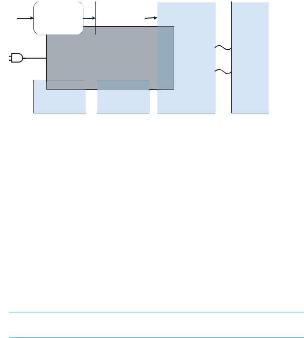
System control
The system control coordinates all the other systems, according to commands from the MPCA.
Figure 1-2 System control
I/O |
FormaƩer |
|
|
Datapath |
|
|
|
|
|
|
|
|
I/O, PDL, UI Control |
|
|
ASIC + memory |
|
|
|
|
Pen I/F |
|
|
|
|
|
|
|
|
|
|
|
|
|
|
|
|
|
|
|
|
|
|
|
|
||
|
|
|
|
|
|
|
Pen |
energy control |
|
|
|
|
|
|
|
|
|
|
|
|
|||
|
|
|
|
|
|
|
|
Pen |
voltage sequencing |
|
Printhead |
|
|
Power supply |
|
|
|
Signal integrity |
|
||||
|
|
|
|
|
Ink-short protecƟon |
|
56,000 nozzles |
||||
|
|
|
|
|
|
|
|
|
|||
|
|
|
|
|
|
|
|
Ink pumps |
|
|
|
|
|
|
|
|
|
|
|
Printhead interconnects |
|
|
|
|
|
|
|
AC control |
|
|
|
|
|||
|
|
|
|
|
|
|
|
||||
|
Engine control |
|
|
|
|
|
Ink supply |
|
|
||
|
|
|
|
|
|
|
|||||
|
|
|
module |
|
|
|
|
|
|
|
|
|
Motor + sensor drive |
|
|
|
|
|
|
|
|
|
|
|
|
|
Airflow system |
|
|
|
|
|
|
|
|
|
|
|
|
|
|
|
|
|
|
|
|
|
|
|
|
|
|
|
|
|
|
|
|
●MPCA
●Data path
●Engine control
●Pen interface
●Power supply
●AC control module
MPCA digital ASIC
The MPCA digital ASIC contains dual ARM CPUs (one at 512 MB and one at 600MHz) that execute rmware code that provides high-level device control. The digital ASIC uses a standard PCle interface to pass data to the formatter ASIC.
MPCA analog ASIC
The MPCA ASIC generates the system voltage for the MPCA, formatter drives the scanner and ADF motors, manages the real-time clock, and drives the fax speaker.
Formatter and data path
 IMPORTANT: Do not simultaneously install a replacement trusted platform module (TPM), hard disk drive (HDD MFP), eMMC (SFP) and formatter PCA. Remove and install each part separately, making sure to turn the printer power on between installations. Failure to do so results in an unusable printer.
The formatter controller ASIC controls the input/output (I/O) control, the user interface, and the rendering of page description language les into printer-speci c commands.
6 Chapter 1 Theory of operation |
ENWW |
Input/output (I/O) control
The printers support 10/100/1000 Ethernet, 802.11 wireless and NFC (some 765 and 780/785 models), a rear USB host port, a rear USB device port, a walk-up USB host port, and analog fax port (some 780/785 models).
The formatter PCA controls the USB device and USB host. The optional dual USB host port accessory is also connected to the formatter after user installation.
Wireless and NFC I/O are provided via a separate radio module.
User interface
The printers contain either a 4.3-in (765 models) or an 8-in (780/785 models) color graphics display. For wireless models, there is an icon on the control panel to denote that the wireless feature is enabled. The printers include a walk-up USB host port for connection to thumb drives.
Formatter digital ASIC
The formatter digital ASIC has dual ARM CPUs (1.2 GHz) that execute rmware code that provides high-level device control. The digital ASIC uses a standard PCle interface to pass data to the engine control ASIC. The formatter rmware is located on either a 320 GB hard-disk drive (HDD) on 780/785 models, or an embedded 8 GHz MultiMedia Card (eMMC) or optional HDD on 765 models.
Additionally, the formatter digital ASIC manages the real-time clock, interfaces to the mass storage controller ASIC, provides control of USB ports, and interfaces with the Ethernet LAN ASIC and fax module.
Formatter Ethernet ASIC
The formatter Ethernet ASIC connects to the formatter digital ASIC with a PCIe interface to transmit and receive network packets.
Formatter mass storage ASIC
The formatter mass storage ASIC bridges between the formatter digital ASIC (via PCIe interface) and the mass storage device (via SATA interface). The 780/785 models use a rotating media HDD, while the 765 models use eMMC an optional HDD is available.
Formatter memory
Formatter memory is installed on-board and there is support for additional DIMM memory installation. The size of the memory on the formatter is 1.5 GB for 765 models and 2.5-3.0 GB for 780/785 models. An optional 1GB DIMM is available as a customer accessory.
Real-time clock
The real-time clock (RTC) allows the fax module to time-stamp outgoing faxes. It also determines the elapsed time between printhead and ISS calibration events. The RTC uses a separate device connected to the formatter digital ASIC, along with a crystal and a battery.
Late point di erentiation con guration (LPDC)
Allows the channel partner to con gure the speed to the printer depending on the customer’s order. LPDC
con guration is stored on the Trusted Platform Module (TPM). There are three methods to program the speed to the printer.
ENWW |
System control 7 |

●Automatic
●O line
●Manual
Engine control
The engine controller digital ASIC receives high-level commands from the MPCA, and it then provides low-level control to the print mechanism. In particular, the engine controller digital ASIC and its rmware control motors, system sensors, and the printhead. The engine controller analog ASICs integrate motor drivers, voltage regulators, sensor interfaces, and supervisory circuits.
Engine controller digital ASIC
The engine controller digital ASIC has a high-performance 480 MHz ARM CPU and DSP co-processors that execute rmware code to provide low-level engine control. It also drives a FPGA which then creates the printhead 15 high-speed LVDS transmission signals. The signals are routed from the engine PCA to the printhead via two large FFC cables. The engine controller digital ASIC receives pre-rendered data from the MPCA digital ASIC over a standard PCle interface.
When a printer enters Sleep mode, many functions of the printer go into a low-power mode. If a print job is received while the printer is in Sleep mode, the printer will take a short period of time to "wake up". This can take up to 15 seconds, which will delay the rst page out (FPO) time accordingly.
Engine controller analog ASICs
The engine uses six analog ASICs to generate the system voltages for the engine, drive the engine motors, control various engine sensors, and monitor printhead power delivery for correct operation.
The engine contains 24 motors, 3 solenoids and 2 fans:
 NOTE: The air flow fan is created using a DC motor.
Certain models might have fewer motors, depending upon the exact con guration of the paper trays.
Motors
●Tray 1 pick motor
●Tray 2 lift motor
●Tray 3 lift motor
●Tray 1 separation motor
●Tray 2 separation motor
●Tray 3 separation motor
●Duplex diverter motor
●Duplex entry motor
●Duplex exit motor
●Finisher diverter motor
●Vertical motor
8 Chapter 1 Theory of operation |
ENWW |

●Deskew motor (front)
●Deskew turn motor (back)
●Scanning carriage motor
●Stack control motor
●Printhead wiper motor
●Eject motor
●Drop detect carriage motor
●Print zone feed motor
●Ink pump motor
●Ink prime motor
●Air flow fan motor (for the air flow fan)
●Printhead lift motor
Solenoids
●Tray 2 pick solenoid (E-clutch)
●Tray 3 pick solenoid (E-clutch)
●Ink prime vent solenoid
Fans
● irflow fan
Aerosol fan
Most motors are DC motors with encoder feedback, to provide precision servo control. These motors are driven directly by one of the engine analog ASICs.
The printer uses many sensors to track the media as it travels through the paper path. Most of these are optical reflective edge detection interrupter (REDI) sensors, which are used in conjunction with mirrors to sense the presence or absence of paper in the paper path. These are carefully aligned and calibrated at the factory, so care must be taken when servicing these sensors. See the remove and Replace chapter of the Repair manual for more details.
Other printed circuit assemblies
In addition to hosting the system ASICs, the engine printed circuit assembly (PCA) incorporates many of the circuits required to interface with sensors and other sub-system components. In some cases, this circuitry is located on a smaller remote PCAs (SLBs) to optimize cable interconnects. The following table lists the various PCAs in the base mechanism engine/MPCA.
 IMPORTANT: Do not simultaneously install a replacement trusted platform module (TPM), hard disk drive (HDD MFP), eMMC (SFP) and formatter PCA. Remove and install each part separately, making sure to turn the printer power on between installations. Failure to do so results in an unusable printer.
ENWW |
System control 9 |

Name |
Description/Function |
Name |
Description/Function |
|
|
|
|
|
|
Left door PCA |
Distribution |
Main bin full sensor PCA |
Main bin paper out sensor |
|
|
|
|
|
|
Printhead lift encoder PCA |
Printhead lift |
Heat zone temperature |
Air flow assembly temperature |
|
|
|
thermistor PCA |
sense |
|
|
|
|
|
|
Feed motor encoder PCA |
Feed motor |
Contact size detect PCA |
Paper length/width detect |
|
|
|
|
|
|
Left front upper PCA |
Distribution |
SIM PCA |
SHAID and distribution |
|
|
|
|
|
|
Air flow assembly PCA |
Air flow assembly |
TT dashboard PCA |
Tabletop control panel interface |
|
|
|
|
|
|
Center rear lower PCA |
Distribution |
HE1 PCA |
Hall e ect sensor |
|
|
|
|
|
|
Left rear lower PCA |
Distribution |
Button on/o PCA |
Base mechanism on/o |
|
|
|
|
interface |
|
|
|
|
|
|
AC control module PCA |
AC control for air flow assembly |
Power button interface PCA |
Base mechanism on/o |
button |
|
|
|
|
|
Printhead registration sensor |
Printhead sensor |
eMMC module PCA (8 GB) |
eMMC module |
|
PCA |
|
|
|
|
|
|
|
|
|
Main logic PCA |
MPCA and engine |
Power button PCA |
Base mechanism on/o |
button |
|
|
|
|
|
Through beam optical drop |
TBODD sensor |
Light pipe PCA |
Light pipe LED |
|
detect (TBODD) PCA |
|
|
|
|
|
|
|
|
|
Drop detect carriage PCA |
TBODD carriage |
Main bin LED PCA |
Main bin LED |
|
|
|
|
|
|
Opto OOP lift plate sensor PCA |
Tandem tray sensor |
Hall e ect left door PCA |
Left door hall e ect |
|
|
|
|
|
|
Separation PCA |
Tandem tray distribution |
Temperature/humidity |
Multiple sensors |
|
|
|
sensor/NVM/HE PCA |
|
|
|
|
|
|
|
Connector width adjust sensor |
Multi-purpose tray sensor |
Carriage drop detect motor PCA |
Motor cable connect |
|
PCA |
|
|
|
|
|
|
|
|
|
Duplex spittoon contact PCA |
Duplex spittoon contact |
Flatbed scan interconnect PCA |
Flatbed scan interface |
|
|
|
|
|
|
Duplex spittoon EEPROM PCA |
Duplex spittoon EEPROM |
ADF PCA |
ADF interface |
|
|
|
|
|
|
Right rear lower PCA |
Distribution |
eMMC module PCA (16 GB) |
eMMC module |
|
|
|
|
|
|
Left rear upper PCA |
Distribution |
Acumen contact PCA |
Acumen PCA |
|
|
|
|
|
|
Pen interface (I/F)
The printhead is the key component that di erentiates this printer from other inkjet printers. The conventional approach is to print a page in horizontal swaths by moving a “scanning” printhead horizontally over a xed sheet of paper, advancing the paper a xed amount, and then printing the next swath. This printer moves the paper underneath a xed page-wide printhead in a single, smooth motion.
Single-pass page-wide printing requires that data and power be delivered to the printhead at a very high rate, while also maintaining good control of paper position as it moves past the printhead nozzles.
The engine printed circuit assembly (PCA) sends power and data to the printhead via two large flat flexible cables (80 pins for the data and 26 pins for the power). The printhead PCA routes power and data to 14 printhead die, which are attached to the printhead PCA using a flexible tab circuit and wire-bonding process.
The printers also contain electronics to control the ink supply station (ISS). The SIM PCA has several functions. It detects low-ink conditions by detecting presence of ink and/or ink foam in the X-chamber. The SIM PCA also collects and distributes electrical signals that drive the ink pump and prime motors, engage the solenoids, and
10 Chapter 1 Theory of operation |
ENWW |

read the ink supply acumen data. All data communications between the ISS and engine PCA are routed through a single 20-pin FFC.
Each ink supply has a memory tag that stores information about its type of ink, the amount of ink remaining, and other critical data. It uses a special authentication scheme to ensure that only genuine HP supplies are used and the printer is not damaged by using invalid supplies. Acumen uses a two-line serial bus which, along with 3.3 V and ground, is cabled via the SIM PCA to the engine PCA and the engine control digital ASIC.
Power supply
The power supply module converts 100-240 VAC to 34 VDC to power the system. The power supply module has a sleep mode that reduces power consumption in system low-power modes. When in its sleep mode, the power supply generates less than 20 W.
The power supply module supplies 34 V to the engine PCA. The power supply module has two operating modes, depending upon the state of its nSLEEP input pin:
●Printing = up to 170 W ( nSLEEP = high logic level)
●Sleep mode = < 20 W ( nSLEEP = low logic level)
The power supply is a self-contained module that can be replaced if it is defective (see the Remove and Replace chapter of the Repair manual).
To ensure safe operation, the power supply will “latch o ” if a persistent over-current fault condition exists. This would typically be caused by a short-circuit from 34 V to ground in the printer. Less severe faults can cause the power supply to latch o , if present for an extended period of time, or if the printer is operated above the recommended operating temperature range. In addition, the power supply output is split into 7 “rails”, each with separate output fusing as an additional safety feature.
 NOTE: The power supply includes fusible links for the AC output from the power supply to the AC control module, and then to the airflow assembly.
AC control module
The AC control module performs the following functions related to the heating elements in the air flow assembly:
●Low-cost voltage monitor
a.The voltage of the outlet, which the printer is attached, is monitored to ensure the printer remains
operational, even in a low-quality-power environment. This is done by instantly shutting o heater power until the minimum voltage threshold is met. Hysteresis is included to avoid rapid fluctuations in voltage.
b.This circuit generates a frequency modulated signal that is sent across the isolation barrier, and
interpreted by rmware in the engine.
●Isolation
–Isolates the low voltage heater control signals from the high voltage AC power that is applied to the heater. This is a safety feature to ensure line transients (i.e. lightning) aren’t coupled into the low voltage system, which could cause damage to the printer or user.
●AC switch
ENWW |
System control 11 |
– |
Switches AC power on/o to the heater using TRIACs. |
●Heating Element Con guration
–Using relays, the heating element con guration is changed between series and parallel, in coordination with applied voltage. This is done to have a predictable temperature pro le that is functional across the full range of worldwide voltages (90-240VAC).
12 Chapter 1 Theory of operation |
ENWW |
Loading...