


 Loading...
McDATA® 4Gb SAN Switch
for HP p-Class BladeSystem user guide
Part number: AA-RW20C-TE Third edition: November 2006
Legal and notice information
©Copyright 2006 Hewlett-Packard Development Company, L.P.
©Copyright 2006 McDATA Corporation.
©Copyright 2006. This software includes technology under a license from QLogic Corporation. All rights reserved.
Hewlett-Packard Company makes no warranty of any kind with regard to this material, including, but not limited to, the implied warranties of merchantability and fitness for a particular purpose. Hewlett-Packard shall not be liable for errors contained herein or for incidental or consequential damages in connection with the furnishing, performance, or use of this material.
This document contains proprietary information, which is protected by copyright. No part of this document may be photocopied, reproduced, or translated into another language without the prior written consent of Hewlett-Packard. The information is provided “as is” without warranty of any kind and is subject to change without notice. The only warranties for HP products and services are set forth in the express warranty statements accompanying such products and services. Nothing herein should be construed as constituting an additional warranty. HP shall not be liable for technical or editorial errors or omissions contained herein.
Firefox® is a registered trademark of Mozilla Foundation.
Java™ is a registered trademark of Sun Microsystems, Inc.
Linux® is a registered trademark of Linus Torvalds.
McDATA® is a registered trademark of McDATA Corporation.
Microsoft®, Windows®, Windows XP®, Windows Server 2000®, Windows Server 2003®, and Internet Explorer® are U.S. registered trademarks of Microsoft Corporation.
Motorola® is a registered trademark of Motorola, Inc.
Netscape Navigator® and Mozilla™ are trademarks or registered trademarks of Netscape Communications Corporation.
PowerPC® is registered trademark of International Business Machines Corporation.
Red Hat® is a registered trademark of Red Hat Software Inc.
SANtegrity Enhanced™ is a trademark of McDATA Corporation.
McDATA Web Server™ is a trademark of McDATA Corporation.
McDATA® 4Gb SAN Switch for HP p-Class BladeSystem user guide

Contents
About this guide. . . . . . . . . . . . . . . . . . . . . . . . . . . . . . . . . . . . . . . . . . . . . . . . . . . . . 7
Intended audience . . . . . . . . . . . . . . . . . . . . . . . . . . . . . . . . . . . . . . . . . . . . . . . . . . . . . . . . . . . . . . . 7 Prerequisites. . . . . . . . . . . . . . . . . . . . . . . . . . . . . . . . . . . . . . . . . . . . . . . . . . . . . . . . . . . . . . . . . . . . 7 Related documentation . . . . . . . . . . . . . . . . . . . . . . . . . . . . . . . . . . . . . . . . . . . . . . . . . . . . . . . . . . . . 7 Document conventions and symbols . . . . . . . . . . . . . . . . . . . . . . . . . . . . . . . . . . . . . . . . . . . . . . . . . . . 8 JDOM license. . . . . . . . . . . . . . . . . . . . . . . . . . . . . . . . . . . . . . . . . . . . . . . . . . . . . . . . . . . . . . . . . . . 8 HP technical support . . . . . . . . . . . . . . . . . . . . . . . . . . . . . . . . . . . . . . . . . . . . . . . . . . . . . . . . . . . . . . 9
HP-authorized reseller. . . . . . . . . . . . . . . . . . . . . . . . . . . . . . . . . . . . . . . . . . . . . . . . . . . . . . . . . . . 9 Helpful web sites . . . . . . . . . . . . . . . . . . . . . . . . . . . . . . . . . . . . . . . . . . . . . . . . . . . . . . . . . . . . . 10
1 Using McDATA Web Server/Element Manager . . . . . . . . . . . . . . . . . . . . . . . . . . . . . . 11
Workstation requirements . . . . . . . . . . . . . . . . . . . . . . . . . . . . . . . . . . . . . . . . . . . . . . . . . . . . . . . . . 12 Starting McDATA Web Server . . . . . . . . . . . . . . . . . . . . . . . . . . . . . . . . . . . . . . . . . . . . . . . . . . . . . . 12 Starting Element Manager in HAFM . . . . . . . . . . . . . . . . . . . . . . . . . . . . . . . . . . . . . . . . . . . . . . . . . . 13 Exiting McDATA Web Server or Element Manager . . . . . . . . . . . . . . . . . . . . . . . . . . . . . . . . . . . . . . . . 13 Setting preferences . . . . . . . . . . . . . . . . . . . . . . . . . . . . . . . . . . . . . . . . . . . . . . . . . . . . . . . . . . . . . . 14 Using online help . . . . . . . . . . . . . . . . . . . . . . . . . . . . . . . . . . . . . . . . . . . . . . . . . . . . . . . . . . . . . . . 15 Viewing software version and copyright information . . . . . . . . . . . . . . . . . . . . . . . . . . . . . . . . . . . . . . . 15 Enabling call home . . . . . . . . . . . . . . . . . . . . . . . . . . . . . . . . . . . . . . . . . . . . . . . . . . . . . . . . . . . . . . 15 Enabling e-mail support . . . . . . . . . . . . . . . . . . . . . . . . . . . . . . . . . . . . . . . . . . . . . . . . . . . . . . . . . . . 15 User interface. . . . . . . . . . . . . . . . . . . . . . . . . . . . . . . . . . . . . . . . . . . . . . . . . . . . . . . . . . . . . . . . . . 16
Menu bar . . . . . . . . . . . . . . . . . . . . . . . . . . . . . . . . . . . . . . . . . . . . . . . . . . . . . . . . . . . . . . . . . . 17 Popup menus . . . . . . . . . . . . . . . . . . . . . . . . . . . . . . . . . . . . . . . . . . . . . . . . . . . . . . . . . . . . . 18 Shortcut keys . . . . . . . . . . . . . . . . . . . . . . . . . . . . . . . . . . . . . . . . . . . . . . . . . . . . . . . . . . . . . 18 McDATA Web Server Fabric tree. . . . . . . . . . . . . . . . . . . . . . . . . . . . . . . . . . . . . . . . . . . . . . . . . . 19 Graphic window . . . . . . . . . . . . . . . . . . . . . . . . . . . . . . . . . . . . . . . . . . . . . . . . . . . . . . . . . . . . . 19 Data windows and tabs . . . . . . . . . . . . . . . . . . . . . . . . . . . . . . . . . . . . . . . . . . . . . . . . . . . . . . . . 20 Selecting switches . . . . . . . . . . . . . . . . . . . . . . . . . . . . . . . . . . . . . . . . . . . . . . . . . . . . . . . . . . . . 20 Selecting ports. . . . . . . . . . . . . . . . . . . . . . . . . . . . . . . . . . . . . . . . . . . . . . . . . . . . . . . . . . . . . . . 20
2 Managing Fabrics . . . . . . . . . . . . . . . . . . . . . . . . . . . . . . . . . . . . . . . . . . . . . . . . . . 21
Securing a fabric . . . . . . . . . . . . . . . . . . . . . . . . . . . . . . . . . . . . . . . . . . . . . . . . . . . . . . . . . . . . . . . 21 Security consistency checklist. . . . . . . . . . . . . . . . . . . . . . . . . . . . . . . . . . . . . . . . . . . . . . . . . . . . . 21 Connection security . . . . . . . . . . . . . . . . . . . . . . . . . . . . . . . . . . . . . . . . . . . . . . . . . . . . . . . . . . . 22 User account security . . . . . . . . . . . . . . . . . . . . . . . . . . . . . . . . . . . . . . . . . . . . . . . . . . . . . . . . . . 22 Remote authentication . . . . . . . . . . . . . . . . . . . . . . . . . . . . . . . . . . . . . . . . . . . . . . . . . . . . . . . . . 22 Device security . . . . . . . . . . . . . . . . . . . . . . . . . . . . . . . . . . . . . . . . . . . . . . . . . . . . . . . . . . . . . . 23
Edit Security dialog . . . . . . . . . . . . . . . . . . . . . . . . . . . . . . . . . . . . . . . . . . . . . . . . . . . . . . . . . 24 Create Security Set dialog . . . . . . . . . . . . . . . . . . . . . . . . . . . . . . . . . . . . . . . . . . . . . . . . . . . . 25 Create Security Group dialog. . . . . . . . . . . . . . . . . . . . . . . . . . . . . . . . . . . . . . . . . . . . . . . . . . 25 Create Security Group Member dialog . . . . . . . . . . . . . . . . . . . . . . . . . . . . . . . . . . . . . . . . . . . 26 Editing the security configuration on a switch . . . . . . . . . . . . . . . . . . . . . . . . . . . . . . . . . . . . . . . 28 Viewing properties of a security set, group, or member . . . . . . . . . . . . . . . . . . . . . . . . . . . . . . . . 28 Security Config dialog. . . . . . . . . . . . . . . . . . . . . . . . . . . . . . . . . . . . . . . . . . . . . . . . . . . . . . . 29 Archiving a security configuration to a file . . . . . . . . . . . . . . . . . . . . . . . . . . . . . . . . . . . . . . . . . 29 Activating a security set . . . . . . . . . . . . . . . . . . . . . . . . . . . . . . . . . . . . . . . . . . . . . . . . . . . . . . 29 Deactivating a security set . . . . . . . . . . . . . . . . . . . . . . . . . . . . . . . . . . . . . . . . . . . . . . . . . . . . 30 Configured Security data window . . . . . . . . . . . . . . . . . . . . . . . . . . . . . . . . . . . . . . . . . . . . . . . 30 Active Security data window . . . . . . . . . . . . . . . . . . . . . . . . . . . . . . . . . . . . . . . . . . . . . . . . . . 30
Fabric services . . . . . . . . . . . . . . . . . . . . . . . . . . . . . . . . . . . . . . . . . . . . . . . . . . . . . . . . . . . . . . 30 Enabling SNMP configuration . . . . . . . . . . . . . . . . . . . . . . . . . . . . . . . . . . . . . . . . . . . . . . . . . 30 Enabling in-band management . . . . . . . . . . . . . . . . . . . . . . . . . . . . . . . . . . . . . . . . . . . . . . . . . 30 Rediscovering a fabric. . . . . . . . . . . . . . . . . . . . . . . . . . . . . . . . . . . . . . . . . . . . . . . . . . . . . . . . . . . . 30 Displaying the event browser . . . . . . . . . . . . . . . . . . . . . . . . . . . . . . . . . . . . . . . . . . . . . . . . . . . . . . . 31
McDATA® 4Gb SAN Switch for HP p-Class BladeSystem user guide |
3 |
Sorting the event browser . . . . . . . . . . . . . . . . . . . . . . . . . . . . . . . . . . . . . . . . . . . . . . . . . . . . . . . 32 Filtering the event browser . . . . . . . . . . . . . . . . . . . . . . . . . . . . . . . . . . . . . . . . . . . . . . . . . . . . . . 33 Saving the event browser to a file . . . . . . . . . . . . . . . . . . . . . . . . . . . . . . . . . . . . . . . . . . . . . . . . . 33 Working with device information and nicknames . . . . . . . . . . . . . . . . . . . . . . . . . . . . . . . . . . . . . . . . . 34 Devices data window. . . . . . . . . . . . . . . . . . . . . . . . . . . . . . . . . . . . . . . . . . . . . . . . . . . . . . . . . . 34 Displaying detailed device information. . . . . . . . . . . . . . . . . . . . . . . . . . . . . . . . . . . . . . . . . . . . . . 35 Managing device port nicknames . . . . . . . . . . . . . . . . . . . . . . . . . . . . . . . . . . . . . . . . . . . . . . . . . 35 Creating a nickname. . . . . . . . . . . . . . . . . . . . . . . . . . . . . . . . . . . . . . . . . . . . . . . . . . . . . . . . 36 Editing a nickname . . . . . . . . . . . . . . . . . . . . . . . . . . . . . . . . . . . . . . . . . . . . . . . . . . . . . . . . . 36 Deleting a nickname . . . . . . . . . . . . . . . . . . . . . . . . . . . . . . . . . . . . . . . . . . . . . . . . . . . . . . . . 36 Exporting nicknames to a file . . . . . . . . . . . . . . . . . . . . . . . . . . . . . . . . . . . . . . . . . . . . . . . . . . 36 Importing a nicknames file . . . . . . . . . . . . . . . . . . . . . . . . . . . . . . . . . . . . . . . . . . . . . . . . . . . . 36 Zoning a fabric . . . . . . . . . . . . . . . . . . . . . . . . . . . . . . . . . . . . . . . . . . . . . . . . . . . . . . . . . . . . . . . . 37 Zoning concepts . . . . . . . . . . . . . . . . . . . . . . . . . . . . . . . . . . . . . . . . . . . . . . . . . . . . . . . . . . . . . 37 Zones . . . . . . . . . . . . . . . . . . . . . . . . . . . . . . . . . . . . . . . . . . . . . . . . . . . . . . . . . . . . . . . . . . 37 Zone sets . . . . . . . . . . . . . . . . . . . . . . . . . . . . . . . . . . . . . . . . . . . . . . . . . . . . . . . . . . . . . . . . 38 Zoning database . . . . . . . . . . . . . . . . . . . . . . . . . . . . . . . . . . . . . . . . . . . . . . . . . . . . . . . . . . 38 Zoning limits and properties. . . . . . . . . . . . . . . . . . . . . . . . . . . . . . . . . . . . . . . . . . . . . . . . . . . 39 Managing the zoning database . . . . . . . . . . . . . . . . . . . . . . . . . . . . . . . . . . . . . . . . . . . . . . . . . . 40 Editing the zoning database. . . . . . . . . . . . . . . . . . . . . . . . . . . . . . . . . . . . . . . . . . . . . . . . . . . 40 Configuring the zoning database . . . . . . . . . . . . . . . . . . . . . . . . . . . . . . . . . . . . . . . . . . . . . . . 42 Interop auto save . . . . . . . . . . . . . . . . . . . . . . . . . . . . . . . . . . . . . . . . . . . . . . . . . . . . . . . . 42 Default zone . . . . . . . . . . . . . . . . . . . . . . . . . . . . . . . . . . . . . . . . . . . . . . . . . . . . . . . . . . . 42 Saving the zoning database to a file . . . . . . . . . . . . . . . . . . . . . . . . . . . . . . . . . . . . . . . . . . . . . 42 Restoring the zoning database from a file . . . . . . . . . . . . . . . . . . . . . . . . . . . . . . . . . . . . . . . . . 42 Restoring the default zoning database. . . . . . . . . . . . . . . . . . . . . . . . . . . . . . . . . . . . . . . . . . . . 43 Removing all zoning definitions . . . . . . . . . . . . . . . . . . . . . . . . . . . . . . . . . . . . . . . . . . . . . . . . 43 Managing the active zone set . . . . . . . . . . . . . . . . . . . . . . . . . . . . . . . . . . . . . . . . . . . . . . . . . . . . 43 Displaying the configured and active zone sets . . . . . . . . . . . . . . . . . . . . . . . . . . . . . . . . . . . . . 44 Creating a zone set . . . . . . . . . . . . . . . . . . . . . . . . . . . . . . . . . . . . . . . . . . . . . . . . . . . . . . . . 45 Activating and deactivating a zone set . . . . . . . . . . . . . . . . . . . . . . . . . . . . . . . . . . . . . . . . . . . 45 Removing a zone from a zone set. . . . . . . . . . . . . . . . . . . . . . . . . . . . . . . . . . . . . . . . . . . . . . . 45 Removing a zone set . . . . . . . . . . . . . . . . . . . . . . . . . . . . . . . . . . . . . . . . . . . . . . . . . . . . . . . . 45 Managing zones . . . . . . . . . . . . . . . . . . . . . . . . . . . . . . . . . . . . . . . . . . . . . . . . . . . . . . . . . . . . . 46 Creating a zone in a zone set . . . . . . . . . . . . . . . . . . . . . . . . . . . . . . . . . . . . . . . . . . . . . . . . . 46 Adding zone members . . . . . . . . . . . . . . . . . . . . . . . . . . . . . . . . . . . . . . . . . . . . . . . . . . . . . . 47 Renaming a zone or a zone set . . . . . . . . . . . . . . . . . . . . . . . . . . . . . . . . . . . . . . . . . . . . . . . . 47 Removing a zone member . . . . . . . . . . . . . . . . . . . . . . . . . . . . . . . . . . . . . . . . . . . . . . . . . . . . 47 Removing a zone from a zone set. . . . . . . . . . . . . . . . . . . . . . . . . . . . . . . . . . . . . . . . . . . . . . . 48 Merging fabrics and zoning . . . . . . . . . . . . . . . . . . . . . . . . . . . . . . . . . . . . . . . . . . . . . . . . . . . . . 48 Zone merge failure . . . . . . . . . . . . . . . . . . . . . . . . . . . . . . . . . . . . . . . . . . . . . . . . . . . . . . . . . 48 Zone merge failure recovery . . . . . . . . . . . . . . . . . . . . . . . . . . . . . . . . . . . . . . . . . . . . . . . . . . 48
3 Managing switches . . . . . . . . . . . . . . . . . . . . . . . . . . . . . . . . . . . . . . . . . . . . . . . . . 49
Managing user accounts . . . . . . . . . . . . . . . . . . . . . . . . . . . . . . . . . . . . . . . . . . . . . . . . . . . . . . . . . . 49 Creating user accounts. . . . . . . . . . . . . . . . . . . . . . . . . . . . . . . . . . . . . . . . . . . . . . . . . . . . . . . . . 50 Removing a user account . . . . . . . . . . . . . . . . . . . . . . . . . . . . . . . . . . . . . . . . . . . . . . . . . . . . . . . 51 Changing a user account password . . . . . . . . . . . . . . . . . . . . . . . . . . . . . . . . . . . . . . . . . . . . . . . . 52 Modifying a user account . . . . . . . . . . . . . . . . . . . . . . . . . . . . . . . . . . . . . . . . . . . . . . . . . . . . . . . 53
Configuring RADIUS servers. . . . . . . . . . . . . . . . . . . . . . . . . . . . . . . . . . . . . . . . . . . . . . . . . . . . . . . . 54 Adding a RADIUS server . . . . . . . . . . . . . . . . . . . . . . . . . . . . . . . . . . . . . . . . . . . . . . . . . . . . . . . 55 Removing a RADIUS server . . . . . . . . . . . . . . . . . . . . . . . . . . . . . . . . . . . . . . . . . . . . . . . . . . . . . . 56 Editing RADIUS server information . . . . . . . . . . . . . . . . . . . . . . . . . . . . . . . . . . . . . . . . . . . . . . . . . 57 Modifying RADIUS server authentication order . . . . . . . . . . . . . . . . . . . . . . . . . . . . . . . . . . . . . . . . 58
Displaying switch information . . . . . . . . . . . . . . . . . . . . . . . . . . . . . . . . . . . . . . . . . . . . . . . . . . . . . . 59 Switch event log . . . . . . . . . . . . . . . . . . . . . . . . . . . . . . . . . . . . . . . . . . . . . . . . . . . . . . . . . . . . . 59 Device and Host Bus Adapter information. . . . . . . . . . . . . . . . . . . . . . . . . . . . . . . . . . . . . . . . . . . . 59 Switch status and operational information. . . . . . . . . . . . . . . . . . . . . . . . . . . . . . . . . . . . . . . . . . . . 60 Port performance statistics. . . . . . . . . . . . . . . . . . . . . . . . . . . . . . . . . . . . . . . . . . . . . . . . . . . . . . . 64
4
Port status and operational information. . . . . . . . . . . . . . . . . . . . . . . . . . . . . . . . . . . . . . . . . . . . . . 64 McDATA Web Server Configured Zonesets data window . . . . . . . . . . . . . . . . . . . . . . . . . . . . . . . . . 64 Configuring port threshold alarms. . . . . . . . . . . . . . . . . . . . . . . . . . . . . . . . . . . . . . . . . . . . . . . . . . . . 65 Paging a switch . . . . . . . . . . . . . . . . . . . . . . . . . . . . . . . . . . . . . . . . . . . . . . . . . . . . . . . . . . . . . . . . 66 Setting the date/time and enabling NTP client . . . . . . . . . . . . . . . . . . . . . . . . . . . . . . . . . . . . . . . . . . . 66 Resetting a switch . . . . . . . . . . . . . . . . . . . . . . . . . . . . . . . . . . . . . . . . . . . . . . . . . . . . . . . . . . . . . . . 67 Configuring a switch. . . . . . . . . . . . . . . . . . . . . . . . . . . . . . . . . . . . . . . . . . . . . . . . . . . . . . . . . . . . . 68 Switch properties . . . . . . . . . . . . . . . . . . . . . . . . . . . . . . . . . . . . . . . . . . . . . . . . . . . . . . . . . . . . . 68 Domain ID and domain ID lock. . . . . . . . . . . . . . . . . . . . . . . . . . . . . . . . . . . . . . . . . . . . . . . . . 69 Syslog . . . . . . . . . . . . . . . . . . . . . . . . . . . . . . . . . . . . . . . . . . . . . . . . . . . . . . . . . . . . . . . . . . 70 Symbolic name. . . . . . . . . . . . . . . . . . . . . . . . . . . . . . . . . . . . . . . . . . . . . . . . . . . . . . . . . . . . 70 Switch administrative states . . . . . . . . . . . . . . . . . . . . . . . . . . . . . . . . . . . . . . . . . . . . . . . . . . . 71 Broadcast support . . . . . . . . . . . . . . . . . . . . . . . . . . . . . . . . . . . . . . . . . . . . . . . . . . . . . . . . . . 71 In-band management. . . . . . . . . . . . . . . . . . . . . . . . . . . . . . . . . . . . . . . . . . . . . . . . . . . . . . . . 71 Fabric Device Management Interface . . . . . . . . . . . . . . . . . . . . . . . . . . . . . . . . . . . . . . . . . . . . 72 Advanced switch properties . . . . . . . . . . . . . . . . . . . . . . . . . . . . . . . . . . . . . . . . . . . . . . . . . . . . . 72 Timeout values . . . . . . . . . . . . . . . . . . . . . . . . . . . . . . . . . . . . . . . . . . . . . . . . . . . . . . . . . . . . 73 Interop mode . . . . . . . . . . . . . . . . . . . . . . . . . . . . . . . . . . . . . . . . . . . . . . . . . . . . . . . . . . . . . 73 System services . . . . . . . . . . . . . . . . . . . . . . . . . . . . . . . . . . . . . . . . . . . . . . . . . . . . . . . . . . . . . . 73 Network properties . . . . . . . . . . . . . . . . . . . . . . . . . . . . . . . . . . . . . . . . . . . . . . . . . . . . . . . . . . . 75 SNMP properties . . . . . . . . . . . . . . . . . . . . . . . . . . . . . . . . . . . . . . . . . . . . . . . . . . . . . . . . . . . . . 76 SNMP configuration . . . . . . . . . . . . . . . . . . . . . . . . . . . . . . . . . . . . . . . . . . . . . . . . . . . . . . . . 77 SNMP trap configuration . . . . . . . . . . . . . . . . . . . . . . . . . . . . . . . . . . . . . . . . . . . . . . . . . . . . . 77 Archiving a switch . . . . . . . . . . . . . . . . . . . . . . . . . . . . . . . . . . . . . . . . . . . . . . . . . . . . . . . . . . . . . . 78 Switch binding . . . . . . . . . . . . . . . . . . . . . . . . . . . . . . . . . . . . . . . . . . . . . . . . . . . . . . . . . . . . . . . . . 78 Restoring a switch. . . . . . . . . . . . . . . . . . . . . . . . . . . . . . . . . . . . . . . . . . . . . . . . . . . . . . . . . . . . . . . 79 Restoring the factory default configuration . . . . . . . . . . . . . . . . . . . . . . . . . . . . . . . . . . . . . . . . . . . . . . 80 Downloading a support file . . . . . . . . . . . . . . . . . . . . . . . . . . . . . . . . . . . . . . . . . . . . . . . . . . . . . . . . 81 Installing Product Feature Enablement keys. . . . . . . . . . . . . . . . . . . . . . . . . . . . . . . . . . . . . . . . . . . . . . 82 Installing firmware . . . . . . . . . . . . . . . . . . . . . . . . . . . . . . . . . . . . . . . . . . . . . . . . . . . . . . . . . . . . . . 83 Displaying hardware status . . . . . . . . . . . . . . . . . . . . . . . . . . . . . . . . . . . . . . . . . . . . . . . . . . . . . . . . 84
4 Managing ports . . . . . . . . . . . . . . . . . . . . . . . . . . . . . . . . . . . . . . . . . . . . . . . . . . . . 85
Port information data window . . . . . . . . . . . . . . . . . . . . . . . . . . . . . . . . . . . . . . . . . . . . . . . . . . . . . . 85 Port statistics data window. . . . . . . . . . . . . . . . . . . . . . . . . . . . . . . . . . . . . . . . . . . . . . . . . . . . . . . . . 88 Viewing and configuring ports . . . . . . . . . . . . . . . . . . . . . . . . . . . . . . . . . . . . . . . . . . . . . . . . . . . . . . 91 Port symbolic name . . . . . . . . . . . . . . . . . . . . . . . . . . . . . . . . . . . . . . . . . . . . . . . . . . . . . . . . . . . 91 Port states . . . . . . . . . . . . . . . . . . . . . . . . . . . . . . . . . . . . . . . . . . . . . . . . . . . . . . . . . . . . . . . . . . 92 Port types . . . . . . . . . . . . . . . . . . . . . . . . . . . . . . . . . . . . . . . . . . . . . . . . . . . . . . . . . . . . . . . . . . 93 Port speeds . . . . . . . . . . . . . . . . . . . . . . . . . . . . . . . . . . . . . . . . . . . . . . . . . . . . . . . . . . . . . . . . . 94 Port transceiver media status . . . . . . . . . . . . . . . . . . . . . . . . . . . . . . . . . . . . . . . . . . . . . . . . . . . . . 94 Device scan . . . . . . . . . . . . . . . . . . . . . . . . . . . . . . . . . . . . . . . . . . . . . . . . . . . . . . . . . . . . . . . . 94 Port binding . . . . . . . . . . . . . . . . . . . . . . . . . . . . . . . . . . . . . . . . . . . . . . . . . . . . . . . . . . . . . . . . . . . 95 Resetting a port . . . . . . . . . . . . . . . . . . . . . . . . . . . . . . . . . . . . . . . . . . . . . . . . . . . . . . . . . . . . . . . . 95 Testing ports . . . . . . . . . . . . . . . . . . . . . . . . . . . . . . . . . . . . . . . . . . . . . . . . . . . . . . . . . . . . . . . . . . 95
Glossary . . . . . . . . . . . . . . . . . . . . . . . . . . . . . . . . . . . . . . . . . . . . . . . . . . . . . . . . . . . 97 Index . . . . . . . . . . . . . . . . . . . . . . . . . . . . . . . . . . . . . . . . . . . . . . . . . . . . . . . . . . . . 101
Figures
1 Element Manager window . . . . . . . . . . . . . . . . . . . . . . . . . . . . . . . . . . . . . . . . . . . . . . . . . . . . . 13 2 Preferences dialog . . . . . . . . . . . . . . . . . . . . . . . . . . . . . . . . . . . . . . . . . . . . . . . . . . . . . . . . . . . 14 3 McDATA Web Server interface . . . . . . . . . . . . . . . . . . . . . . . . . . . . . . . . . . . . . . . . . . . . . . . . . . 16 4 McDATA Web Server fabric tree . . . . . . . . . . . . . . . . . . . . . . . . . . . . . . . . . . . . . . . . . . . . . . . . . 19 5 Edit Security dialog . . . . . . . . . . . . . . . . . . . . . . . . . . . . . . . . . . . . . . . . . . . . . . . . . . . . . . . . . . 24 6 Create Security Set dialog . . . . . . . . . . . . . . . . . . . . . . . . . . . . . . . . . . . . . . . . . . . . . . . . . . . . . 25 7 Create Security Group dialog . . . . . . . . . . . . . . . . . . . . . . . . . . . . . . . . . . . . . . . . . . . . . . . . . . . 25 8 Create a Security Group Member dialog . . . . . . . . . . . . . . . . . . . . . . . . . . . . . . . . . . . . . . . . . . . 26 9 Security Config dialog . . . . . . . . . . . . . . . . . . . . . . . . . . . . . . . . . . . . . . . . . . . . . . . . . . . . . . . . 29
McDATA® 4Gb SAN Switch for HP p-Class BladeSystem user guide |
5 |
10 Events browser . . . . . . . . . . . . . . . . . . . . . . . . . . . . . . . . . . . . . . . . . . . . . . . . . . . . . . . . . . . . . 31 11 Filter events dialog. . . . . . . . . . . . . . . . . . . . . . . . . . . . . . . . . . . . . . . . . . . . . . . . . . . . . . . . . . . 33 12 Devices data window. . . . . . . . . . . . . . . . . . . . . . . . . . . . . . . . . . . . . . . . . . . . . . . . . . . . . . . . . 34 13 Detailed devices display dialog. . . . . . . . . . . . . . . . . . . . . . . . . . . . . . . . . . . . . . . . . . . . . . . . . . 35 14 Edit zoning dialog . . . . . . . . . . . . . . . . . . . . . . . . . . . . . . . . . . . . . . . . . . . . . . . . . . . . . . . . . . . 40 15 Zoning Config dialog (McDATA Fabric Mode) . . . . . . . . . . . . . . . . . . . . . . . . . . . . . . . . . . . . . . . 42 16 Configured zonesets data window. . . . . . . . . . . . . . . . . . . . . . . . . . . . . . . . . . . . . . . . . . . . . . . . 44 17 Active zone set data window . . . . . . . . . . . . . . . . . . . . . . . . . . . . . . . . . . . . . . . . . . . . . . . . . . . 44 18 User Account Administration dialog – Add Account tab page . . . . . . . . . . . . . . . . . . . . . . . . . . . . . 50 19 User Account Administration Dialog – Remove Account tab page . . . . . . . . . . . . . . . . . . . . . . . . . . 51 20 User Account Administration dialog – Change Password tab page . . . . . . . . . . . . . . . . . . . . . . . . . 52 21 User Account Administration dialog - Modify Account tab page . . . . . . . . . . . . . . . . . . . . . . . . . . . 53 22 RADIUS Server Information dialog—Add Server tab page . . . . . . . . . . . . . . . . . . . . . . . . . . . . . . . 55 23 RADIUS Server Information dialog—Remove Server tab page . . . . . . . . . . . . . . . . . . . . . . . . . . . . . 56 24 RADIUS Server Information dialog—Edit Server tab page . . . . . . . . . . . . . . . . . . . . . . . . . . . . . . . . 57 25 RADIUS Server Information dialog—Modify Authentication Order tab page . . . . . . . . . . . . . . . . . . . 58 26 Switch data window . . . . . . . . . . . . . . . . . . . . . . . . . . . . . . . . . . . . . . . . . . . . . . . . . . . . . . . . . 60 27 McDATA Web Server Configured Zonesets data window. . . . . . . . . . . . . . . . . . . . . . . . . . . . . . . . 64 28 Port Threshold Alarm Configuration dialog . . . . . . . . . . . . . . . . . . . . . . . . . . . . . . . . . . . . . . . . . . 65 29 Port threshold alarm example . . . . . . . . . . . . . . . . . . . . . . . . . . . . . . . . . . . . . . . . . . . . . . . . . . . 66 30 Switch properties dialog. . . . . . . . . . . . . . . . . . . . . . . . . . . . . . . . . . . . . . . . . . . . . . . . . . . . . . . 68 31 Advanced switch properties dialog . . . . . . . . . . . . . . . . . . . . . . . . . . . . . . . . . . . . . . . . . . . . . . . 72 32 System services dialog . . . . . . . . . . . . . . . . . . . . . . . . . . . . . . . . . . . . . . . . . . . . . . . . . . . . . . . . 73 33 Network properties dialog . . . . . . . . . . . . . . . . . . . . . . . . . . . . . . . . . . . . . . . . . . . . . . . . . . . . . 75 34 SNMP Properties dialog . . . . . . . . . . . . . . . . . . . . . . . . . . . . . . . . . . . . . . . . . . . . . . . . . . . . . . . 76 35 Restore Dialogs – Full Restore and Selective Restore tab pages . . . . . . . . . . . . . . . . . . . . . . . . . . . . 79 36 Features Licenses dialog . . . . . . . . . . . . . . . . . . . . . . . . . . . . . . . . . . . . . . . . . . . . . . . . . . . . . . . 82 37 Add License Key dialog . . . . . . . . . . . . . . . . . . . . . . . . . . . . . . . . . . . . . . . . . . . . . . . . . . . . . . . 82 38 Hardware status LEDs. . . . . . . . . . . . . . . . . . . . . . . . . . . . . . . . . . . . . . . . . . . . . . . . . . . . . . . . . 84 39 Port Information data window . . . . . . . . . . . . . . . . . . . . . . . . . . . . . . . . . . . . . . . . . . . . . . . . . . . 85 40 Port Statistics data window . . . . . . . . . . . . . . . . . . . . . . . . . . . . . . . . . . . . . . . . . . . . . . . . . . . . . 88 41 Port Properties dialog . . . . . . . . . . . . . . . . . . . . . . . . . . . . . . . . . . . . . . . . . . . . . . . . . . . . . . . . . 91 42 Port Diagnostics dialog. . . . . . . . . . . . . . . . . . . . . . . . . . . . . . . . . . . . . . . . . . . . . . . . . . . . . . . . 95
Tables
1 Document conventions . . . . . . . . . . . . . . . . . . . . . . . . . . . . . . . . . . . . . . . . . . . . . . . . . . . . . . . . . . 8 2 Workstation requirements . . . . . . . . . . . . . . . . . . . . . . . . . . . . . . . . . . . . . . . . . . . . . . . . . . . . . . . 12 3 Menu Bar Options . . . . . . . . . . . . . . . . . . . . . . . . . . . . . . . . . . . . . . . . . . . . . . . . . . . . . . . . . . . 17 4 Severity levels . . . . . . . . . . . . . . . . . . . . . . . . . . . . . . . . . . . . . . . . . . . . . . . . . . . . . . . . . . . . . . . 32 5 Devices Data Window Entries . . . . . . . . . . . . . . . . . . . . . . . . . . . . . . . . . . . . . . . . . . . . . . . . . . . . 34 6 Edit zoning dialog tool bar buttons and icons . . . . . . . . . . . . . . . . . . . . . . . . . . . . . . . . . . . . . . . . . 41 7 Factory user accounts. . . . . . . . . . . . . . . . . . . . . . . . . . . . . . . . . . . . . . . . . . . . . . . . . . . . . . . . . . 49 8 Switch data window entries . . . . . . . . . . . . . . . . . . . . . . . . . . . . . . . . . . . . . . . . . . . . . . . . . . . . . 60 9 Switch resets . . . . . . . . . . . . . . . . . . . . . . . . . . . . . . . . . . . . . . . . . . . . . . . . . . . . . . . . . . . . . . . . 67 10 Corresponding domain ID values by interop mode . . . . . . . . . . . . . . . . . . . . . . . . . . . . . . . . . . . . . 70 11 Switch Administrative States . . . . . . . . . . . . . . . . . . . . . . . . . . . . . . . . . . . . . . . . . . . . . . . . . . . . . 71 12 Timeout values . . . . . . . . . . . . . . . . . . . . . . . . . . . . . . . . . . . . . . . . . . . . . . . . . . . . . . . . . . . . . . 73 13 Network IP configuration parameters . . . . . . . . . . . . . . . . . . . . . . . . . . . . . . . . . . . . . . . . . . . . . . . 75 14 SNMP configuration parameters . . . . . . . . . . . . . . . . . . . . . . . . . . . . . . . . . . . . . . . . . . . . . . . . . . 77 15 SNMP trap configuration parameters . . . . . . . . . . . . . . . . . . . . . . . . . . . . . . . . . . . . . . . . . . . . . . . 77 16 Factory default configuration settings . . . . . . . . . . . . . . . . . . . . . . . . . . . . . . . . . . . . . . . . . . . . . . . 80 17 Port information data window entries . . . . . . . . . . . . . . . . . . . . . . . . . . . . . . . . . . . . . . . . . . . . . . . 86 18 Port statistics data window entries . . . . . . . . . . . . . . . . . . . . . . . . . . . . . . . . . . . . . . . . . . . . . . . . . 88 19 Port administrative and operational states . . . . . . . . . . . . . . . . . . . . . . . . . . . . . . . . . . . . . . . . . . . . 92 20 Port types . . . . . . . . . . . . . . . . . . . . . . . . . . . . . . . . . . . . . . . . . . . . . . . . . . . . . . . . . . . . . . . . . . 93 21 Port speeds . . . . . . . . . . . . . . . . . . . . . . . . . . . . . . . . . . . . . . . . . . . . . . . . . . . . . . . . . . . . . . . . . 93 22 Port Transceiver media view . . . . . . . . . . . . . . . . . . . . . . . . . . . . . . . . . . . . . . . . . . . . . . . . . . . . . 94
6

About this guide
This manual describes the McDATA® Web Server™ and McDATA Element Manager™ management tools for the McDATA 4Gb SAN Switch. McDATA Element Manager is referred to as Element Manager throughout this document. The McDATA 4Gb SAN Switch is a 10-port non-blocking Fibre Channel (FC) switch. This manual defines the features, components, and performance characteristics of the McDATA 4Gb SAN Switch.
The embedded McDATA Web Server and the Element Manager applications are the focus of this manual which is organized as follows:
•”Using McDATA Web Server/Element Manager” on page 11 describes how to use McDATA Web Server and Element Manager, their menus, and displays.
•”Managing Fabrics” on page 21 describes fabric management tasks of the McDATA Web Server.
•”Managing switches” on page 49 describes switch management tasks of the McDATA Web Server and Element Manager.
•”Managing ports” on page 85 describes port management tasks of the McDATA Web Server and Element Manager.
A glossary of terms and an index are also provided.
Intended audience
This manual introduces the switch management products and explains their installation and use. It is intended for users responsible for installing and using switch management tools.
Prerequisites
Prerequisites for using this product include:
•Knowledge of operation systems
•Knowledge of related hardware/software
Related documentation
In addition to this guide, please refer to the following documents for this product:
•McDATA 4Gb SAN Switch for HP p-Class BladeSystem release notes AA-RW1ZD-TE
•McDATA 4Gb SAN Switch for HP p-Class BladeSystem quick setup instructions A8001-90002
•McDATA 4Gb SAN Switch for HP p-Class BladeSystem installation guide AA-RW1XC-TE
•McDATA 4Gb SAN Switch for HP p-Class BladeSystem command line interface guide, AA-RWEJA-TE
•HP StorageWorks HA-Fabric Manager user guide AA-RS2CH-TE
•HP StorageWorks HA-Fabric Manager release notes AA-RUR6J-TE
These and other HP documents can be found on the HP documents web site: http://www.hp.com/support/.
McDATA® 4Gb SAN Switch for HP p-Class BladeSystem user guide |
7 |

Document conventions and symbols
Table 1 Document conventions
Convention |
Element |
|
|
|
|
Medium blue text: Figure 1 |
Cross-reference links and e-mail addresses |
|
|
|
|
Medium blue, underlined text |
Web site addresses |
|
(http://www.hp.com) |
|
|
|
|
|
Bold font |
• |
Key names |
|
• Text typed into a GUI element, such as into a box |
|
|
• GUI elements that are clicked or selected, such as menu and list |
|
|
|
items, buttons, and check boxes |
|
|
|
Italics font |
Text emphasis |
|
|
|
|
Monospace font |
• File and directory names |
|
|
• |
System output |
|
• |
Code |
|
• Text typed at the command-line |
|
|
|
|
Monospace, italic font |
• |
Code variables |
|
• Command-line variables |
|
|
|
|
Monospace, bold font |
Emphasis of file and directory names, system output, code, and text |
|
|
typed at the command line |
|
|
|
|
 WARNING! Indicates that failure to follow directions could result in bodily harm or death.
 CAUTION: Indicates that failure to follow directions could result in damage to equipment or data.
 IMPORTANT: Provides clarifying information or specific instructions.
 NOTE: Provides additional information.
 TIP: Provides helpful hints and shortcuts.
JDOM license
This product includes software developed by the JDOM Project (http://www.jdom.org/). Copyright (C) 2000—2002 Brett McLaughlin & Jason Hunter. All rights reserved.
Redistribution and use in source and binary forms, with or without modification, are permitted provided that the following conditions are met:
1.Redistributions of source code must retain the above copyright notice, this list of conditions, and the following disclaimer.
8
2.Redistributions in binary form must reproduce the above copyright notice, this list of conditions, and the disclaimer that follows these conditions in the documentation and/or other materials provided with the distribution.
3.The name "JDOM" must not be used to endorse or promote products derived from this software without prior written permission. For written permission, please contact license@jdom.org.
4.Products derived from this software may not be called "JDOM", nor may "JDOM" appear in their name, without prior written permission from the JDOM Project Management (pm@jdom.org).
In addition, we request (but do not require) that you include in the end-user documentation provided with the redistribution and/or in the software itself an acknowledgement equivalent to the following: "This product includes software developed by the JDOM Project (http://www.jdom.org/)."
Alternatively, the acknowledgment may be graphical using the logos available at
http://www.jdom.org/images/logos.
THIS SOFTWARE IS PROVIDED ``AS IS'' AND ANY EXPRESSED OR IMPLIED WARRANTIES, INCLUDING, BUT NOT LIMITED TO, THE IMPLIED WARRANTIES OF MERCHANTABILITY AND FITNESS FOR A PARTICULAR PURPOSE ARE DISCLAIMED. IN NO EVENT SHALL THE JDOM AUTHORS OR THE PROJECT CONTRIBUTORS BE LIABLE FOR ANY DIRECT, INDIRECT, INCIDENTAL, SPECIAL, EXEMPLARY, OR CONSEQUENTIAL DAMAGES (INCLUDING, BUT NOT LIMITED TO, PROCUREMENT OF SUBSTITUTE GOODS OR SERVICES; LOSS OF USE, DATA, OR PROFITS; OR BUSINESS INTERRUPTION) HOWEVER CAUSED AND ON ANY THEORY OF LIABILITY, WHETHER IN CONTRACT, STRICT LIABILITY, OR TORT (INCLUDING NEGLIGENCE OR OTHERWISE) ARISING IN ANY WAY OUT OF THE USE OF THIS SOFTWARE, EVEN IF ADVISED OF THE POSSIBILITY OF SUCH DAMAGE.
This software consists of voluntary contributions made by many individuals on behalf of the JDOM Project and was originally created by Brett McLaughlin <brett@jdom.org> and Jason Hunter <jhunter@jdom.org>. For more information on the JDOM Project, please see <http://www.jdom.org/>.
HP technical support
Telephone numbers for worldwide technical support are listed on the HP support web site: http://www.hp.com/support/.
Collect the following information before calling:
•Technical support registration number (if applicable)
•Product serial numbers
•Product model names and numbers
•Applicable error messages
•Operating system type and revision level
•Detailed, specific questions
For continuous quality improvement, calls may be recorded or monitored.
HP strongly recommends that customers sign up online using the Subscriber's choice web site: http://www.hp.com/go/e-updates.
•Subscribing to this service provides you with e-mail updates on the latest product enhancements, newest versions of drivers, and firmware documentation updates as well as instant access to numerous other product resources.
•After signing up, you can quickly locate your products by selecting Business support and then Storage under Product Category.
HP-authorized reseller
For the name of your nearest HP-authorized reseller:
•In the United States, call 1-800-282-6672.
•Elsewhere, visit the HP web site: http://www.hp.com. Then click Contact HP to find locations and telephone numbers.
McDATA® 4Gb SAN Switch for HP p-Class BladeSystem user guide |
9 |
Helpful web sites
For other product information, see the following HP web sites:
•http://www.hp.com
•http://www.hp.com/go/storage
•http://www.hp.com/support/
•http://www.docs.hp.com
•http://h71028.www7.hp.com/enterprise/cache/80316-0-0-0-121.html
10
1 Using McDATA Web Server/Element Manager
This section describes how to use the McDATA Web Server and Element Manager applications and their menus. McDATA Web Server is a graphical user interface that provides both fabric and switch module management functions. Because McDATA Web Server resides in the switch firmware, no installation is needed. You can run one instance of the McDATA Web Server at a time by opening the switch IP address with an internet browser. McDATA Web Server is best used to manage a single fabric consisting only of McDATA 4Gb SAN switches.
Element Manager is a graphical user interface for managing a single McDATA 4Gb SAN Switch through either the High Availability Fabric Manager (HAFM) or the Enterprise Fabric Connectivity Manager (EFCM) application. HAFM, EFCM and Element Manager are essential tools for managing multiple fabrics or a single fabric consisting of McDATA 4Gb SAN switches, HP StorageWorks M-Series switches, or McDATA switches. References to HAFM in this document also apply to EFCM.
 IMPORTANT: Element Manager is available only with the Element Manager Product Features Enablement (PFE) key. See ”Installing Product Feature Enablement keys” on page 82 for information about installing a PFE key. To obtain the McDATA 4Gb SAN Switch serial number and PFE key, follow the step-by-step instructions on the firmware feature entitlement request certificate for the PFE key. You can obtain a PFE key from the web at: www.webkey.external.hp.com.
 NOTE: Unless stated otherwise, the features described in this document apply to McDATA Web Server and Element Manager
The following topics are covered:
•Workstation requirements, page 12
•Starting McDATA Web Server, page 12
•Starting Element Manager in HAFM, page 13
•Exiting McDATA Web Server or Element Manager, page 13
•Setting preferences, page 14
•Using online help, page 15
•Viewing software version and copyright information, page 15
•Enabling call home, page 15
•Enabling e-mail support, page 15
•User interface, page 16
McDATA® 4Gb SAN Switch for HP p-Class BladeSystem user guide 11
Workstation requirements
The requirements for fabric management workstations running the McDATA Web Server web applet are listed in Table 2.
Table 2 Workstation requirements
Operating System |
Microsoft® Windows Server 2000, Windows Server 2003 SP1, |
|
Windows XP® |
|
Red Hat® Enterprise Linux® 3 and 4 |
|
|
Memory |
256 MB or more |
|
|
Processor |
500 MHz or faster |
|
|
Hardware |
RJ-45 Ethernet port, |
|
|
Internet Browser |
Microsoft Internet Explorer® 5.0 and later |
|
Netscape® Navigator® 6.0 and later |
|
Mozilla™ 1.5 or later |
|
Mozilla Firefox® 1.0.7 or later |
|
Java 2 Runtime Environment to support the McDATA Web Server |
|
|
Starting McDATA Web Server
To start McDATA Web Server after the switch is operational, enter the switch IP address in an internet browser. The workstation used to manage the switch must be able to connect to the default switch IP address 10.0.0.1.
1.At the workstation, enter the default switch IP address (10.0.0.1) in an internet browser. If your workstation does not have the Java 2 Run Time Environment program, you will be prompted to download it.
2.Enter the login name (default is admin) and password (default is password) in the Add a New Fabric dialog.
3.Click Add Fabric. If you do not have a secure Ethernet connection, the Non Secure Connection Check dialog will prompt you to establish a non-secure connection.
4.The Password Change Required dialog prompts you to change the default password. Click the OK button. This dialog will prompt you to change the default password each time you log in until you change it. See ”Managing user accounts” on page 49 for information about changing the password.
5.Select Switch > Network Properties.
6.Change the IP Address, Subnet Mask, and Gateway settings to reflect your desired network configuration in the Network Properties dialog.
7.Click OK.
8.Close the browser window to close the McDATA Web Server application. The switch is now ready to be managed through your network.
9.Repeat steps 1—4 using the switch's newly configured IP address to launch the McDATA Web Server application once your configured switch is connected to the network.
12

Starting Element Manager in HAFM
To use Element Manager, the HAFM client application must be running on your workstation, or you must be accessing HAFM on the HAFM Appliance. See your HAFM documentation for information about starting and using HAFM. To start Element Manager in HAFM, add the switch IP address to the discovery list.
Locate and double click the switch in the fabric map to open. You can also select the switch and select Element Manager from the application list. HAFM displays the Element Manager window shown in
Figure 1.
Figure 1 Element Manager window
Exiting McDATA Web Server or Element Manager
To exit a McDATA Web Server session, close the browser window. To exit a Element Manager session, select File > Exit.
McDATA® 4Gb SAN Switch for HP p-Class BladeSystem user guide 13

Setting preferences
You can customize the following preference settings for McDATA Web Server and Element Manager:
•Change the location of the working directory in which to save files.
•Change the location of the browser used to view the online help.
•Select a Display Dialog When Making Non-secure Connections option. If enabled, the Non-secure Connections Check dialog is displayed when you attempt to open a non-secure fabric. You then have the option of opening a non-secure fabric. If disabled, you cannot open a fabric with a non-secure connection.
•Enable (default) or disable the Event Browser. See ”Displaying the event browser” on page 31. If the Event Browser is enabled using the Preferences dialog as shown in Figure 2, the next time McDATA Web Server is started, all events will be displayed. If the Event Browser is disabled when McDATA Web Server is started and later enabled, only those events from the time the Event Browser was enabled and forward will be displayed.
•Choose the default port view when opening the faceplate display. You can set the faceplate to reflect the current port type (default), port speed, port operational state, or port transceiver media. Regardless of the default port view you choose, you can change the port view in the faceplate display by opening the View menu and selecting a different port view option. See the corresponding subsection for more information:
•Port types, page 93
•Port states, page 92
•Port speeds, page 94
•Port transceiver media status, page 94
Figure 2 Preferences dialog
To set preferences:
1.Select File > Preferences to open the Preferences dialog.
2.Enter or browse for paths to the working directory and browser.
3.Choose the preferences you want in the Application-wide Options area.
4.Click OK to save the changes.
14

Using online help
Online help is available for the McDATA Web Server and Element Manager applications and their functions. Online help is also context-sensitive, that is, the online help opens to the topic that describes the dialog you have open. To open online help, choose one of the following:
•Select Help > Help Topics.
•Click Help in dialogs to display context-sensitive help in dialogs.
•Press the F1 function key
Viewing software version and copyright information
Select Help > About to view software version and copyright information.
Enabling call home
The call-home feature enables the server platform to automatically connect with a support center to report system problems. The support center server accepts calls from the server platform, logs reported events, and notifies one or more support center representatives. The default state is disabled. To configure telephone numbers and other information for the call-home feature, see your HAFM Manual for details.
You must enable call-home event notification through HAFM before enabling this function through the Element Manager for the individual switch. At the bottom of HAFM desktop window is an icon that indicates whether the call-home feature is enabled. An X over the phone icon indicates that the call-home feature is disabled.
To enable call-home support for system problems using Element Manager:
1.Select File > HAFM Settings.
2.Select Call Home Support in the pull-down menu to mark the check box. To disable call home support, select the option to remove the check mark from the check box.
Enabling e-mail support
The e-mail support function on the Element Manager enables e-mail notification for events that occur on a selected switch. The default state is disabled. e-mail addresses and the simple mail transfer protocol (SMTP) server address for e-mail notification of director events must be configured through HAFM. See your HAFM Manual for instructions on configuring e-mail.
NOTE: e-mail recipients are configured in HAFM through the Email Event Notification Setup dialog box. A valid SMTP address is configured in this dialog box.
To enable e-mail support using Element Manager:
1.Select File > HAFM Settings.
2.Select Email Support in the pull-down menu to mark the check box. To disable e-mail support, select the option to remove the check mark from the check box.
McDATA® 4Gb SAN Switch for HP p-Class BladeSystem user guide 15
User interface
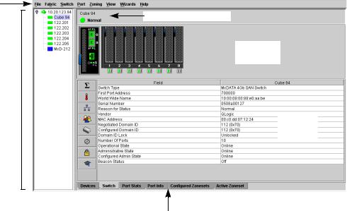
The McDATA Web Server and Element Manager applications share a common interface as shown in Figure 3. The interface consists of a menu bar, fabric tree, graphic window, data windows (some with buttons), and data window tabs. The switch faceplate is displayed in the graphic window and shows the front of a single switch and its ports. The fabric name is displayed for reference in the fabric tree above the switch names. Click a switch name or icon to display a different switch faceplate in the graphic window. Information displayed in the data windows corresponds to the data window tab selected.
The Element Manager application uses a modified faceplate display with fewer menus, no fabric tree, and fewer data window tabs.
Menu |
|
bar |
Switch name /status |
Graphic window
Fabric tree
Data window
Data window tabs
Figure 3 McDATA Web Server interface
16
Menu bar
The McDATA Web Server and Element Manager menu bar options are listed in Table 3.
Table 3 Menu Bar Options
Menu |
McDATA Web Server Options |
Element Manager Options |
|
|
|
File |
Preferences |
Preferences |
|
|
HAFM Settings |
|
|
Exit |
|
|
|
Fabric |
Nicknames |
Not applicable |
|
Rediscover Fabric |
|
|
Show Event Browser |
|
|
|
|
Switch |
Archive |
Archive |
|
Restore |
Restore |
|
User Accounts |
User Accounts |
|
Set Date/Time |
Set Date/Time |
|
Switch Properties |
Switch Properties |
|
Advanced Switch Properties |
Advanced Switch Properties |
|
Services |
Services |
|
|
Switch Binding |
|
Network Properties |
Security Consistency Checklist |
|
Network Properties |
|
|
SNMP Properties |
SNMP Properties |
|
Toggle Beacon |
Toggle Beacon |
|
Load Firmware |
Port Threshold Alarm Configuration |
|
Load Firmware |
|
|
Reset Switch |
Reset Switch |
|
Restore Factory Defaults |
Restore Factory Defaults |
|
Features |
Features |
|
Radius Servers1 |
Radius Servers1 |
|
Download Support File |
Download Support File |
|
|
|
Port |
Port Properties |
Port Properties |
|
Advanced Port Properties |
Advanced Port Properties |
|
Reset Port |
Reset Port |
|
|
Port Binding |
|
Port Diagnostics |
Port Diagnostics |
|
|
|
Zoning |
Edit Zoning |
Edit Zoning Config |
|
Edit Zoning Config |
|
|
Activate Zone Set |
|
|
Deactivate Zone Set |
|
|
Restore Default Zoning |
|
|
|
|
Security1 |
Not applicable |
Edit Security |
|
|
Edit Security Config |
|
|
Activate Security Set |
|
|
Deactivate Security Set |
|
|
|
View |
Refresh |
Refresh |
|
|
Show Event Browser |
|
View Port Types |
View Port Types |
|
View Port States |
View Port States |
|
View Port Speeds |
View Port Speeds |
|
View Port Media |
View Port Media |
|
|
|
McDATA® 4Gb SAN Switch for HP p-Class BladeSystem user guide 17
Table 3 Menu Bar Options (Continued)
Menu |
McDATA Web Server Options |
Element Manager Options |
|
|
|
Wizards |
Configuration Wizard |
Same as McDATA Web Server |
|
|
|
Help |
Help Topics |
Same as McDATA Web Server |
|
About |
|
|
|
|
1. Requires SANtegrity PFE key and Secure Sockets Layer (SSL) enabled. See System services, page 73.
Popup menus
Popup menus are displayed when you right-click the switch faceplate image in the graphic window. Popup menu options give you quick access to the following common tasks and dialogs:
•Refreshing a switch
•Selecting all ports or blades
•Properties dialogs (Port, Blade, Switch, Network, and SNMP)
•Services dialog
•Diagnostics dialogs (Port and Blade)
Shortcut keys
Shortcut key combinations provide an alternative method of accessing menu options in the web applet. For example, to open the Preferences dialog, press Alt+F, then press R. The shortcut key combinations are not case-sensitive.
18

McDATA Web Server Fabric tree
McDATA Web Server enables you to manage McDATA 4Gb SAN Switches and observe other switches in the fabric. The fabric tree, shown in Figure 4, provides access to the faceplate display of each McDATA 4Gb SAN Switch in the fabric, and displays the presence of other switches in the fabric. Click a switch name or icon of a McDATA 4Gb SAN Switch to display that switch faceplate in the graphic window. The window width of the fabric tree can be adjusted by clicking and dragging the moveable window border.
The fabric tree entry has a small icon next to it that uses color to indicate operational status.
•A green icon indicates normal operation.
•A yellow icon indicates that a switch is operational, but may require attention to maintain maximum performance.
•A red icon indicates a potential failure or non-operational state as when the switch is offline.
•A blue icon indicates that a switch is unknown, unreachable, or unmanageable through the McDATA 4Gb SAN Switch.
If the status of the fabric is not normal, the fabric icon in the fabric tree will indicate the reason for the abnormal status. The same message is provided when you rest the mouse on the fabric icon in the fabric tree.
Fabric entry
Entry handle
Switch entries
Figure 4 McDATA Web Server fabric tree
Graphic window
The graphic window shows the switch faceplate display. The window height can be adjusted by clicking and dragging the window border that it shares with the data window.
McDATA® 4Gb SAN Switch for HP p-Class BladeSystem user guide 19
Data windows and tabs
The data window presents a table of data and statistics associated with the selected tab for the switch displayed in the graphic window. Use the scroll bar to browse through the data. The window length can be adjusted by clicking and dragging the border that it shares with the graphic window.
Adjust the column width by moving the pointer over the column heading border shared by two columns until a right/left arrow graphic is displayed. Click and drag the arrow to the desired width.
Click on the following tabs to open the corresponding data window:
•Devices—Displays information about devices (hosts and storage targets) connected to the switch. See ”Devices data window” on page 34 for more information.
•Switch—Displays current network and switch configuration data for the selected switches. See ”Switch status and operational information” on page 60 for more information.
•Port Statistics—Displays performance data for the selected ports. See ”Port statistics data window” on page 88 for more information.
•Port Information—Displays information for the selected ports. See ”Port statistics data window” on page 88 for more information.
•Configured Zonesets—Displays all zone sets, zones, and zone membership in the zoning database. This data window is available in McDATA Web Server only. See ”McDATA Web Server Configured Zonesets data window” on page 64.
•Active Zoneset—Displays the active zone set for the fabric including zones and their member ports. This data window is available only in McDATA Web Server. See ”Displaying the configured and active zone sets” on page 44 for more information about this data window. See ”Zoning concepts” on page 37 for information about zone sets and zones.
•Configured Security—Displays all security definitions currently saved in the database (Element Manager only).
•• Active Security—Displays the active security set (Element Manager only).
Selecting switches
Switches are selectable in the fabric tree (McDATA Web Server only). Click a McDATA 4Gb SAN Switch to display its faceplate display in the graphic window. See ”Managing switches” on page 49 for detailed switch information.
Selecting ports
Ports are selectable and serve as access points for other displays and menus. You select ports to display information about them in the data window or to modify them. Context-sensitive popup menus are displayed when you right-click the faceplate image or on a port icon. See ”Managing ports” on page 85 for detailed port information.
Selected ports in the faceplate display are outlined in white. You can select ports the following ways.
•To select a port, click the port.
•To select all ports, right-click on the faceplate image and select Select All Ports from the popup menu.
•To un-select all ports, click the faceplate anywhere away from a port.
•To un-select a particular port, hold down the Control key while clicking each port.
20
2 Managing Fabrics
This section describes the following tasks that manage fabrics using McDATA Web Server:
•Securing a fabric, page 21
•Rediscovering a fabric, page 30
•Displaying the event browser, page 31
•Working with device information and nicknames, page 34
•Zoning a fabric, page 37
Securing a fabric
Fabric security consists of the following:
•Security consistency checklist, page 21
•Connection security, page 22
•User account security, page 22
•Remote authentication, page 22
•Device security, page 23
•Fabric services, page 30
Security consistency checklist
 IMPORTANT: The security consistency checklist is available only with Element Manager, which requires the Element Manager PFE key. See ”Installing Product Feature Enablement keys” on page 82 for more information about installing a PFE key. To obtain the McDATA 4Gb SAN Switch serial number and PFE key, follow the step-by-step instructions on the firmware feature entitlement request certificate for the PFE key. You can obtain a PFE key from the web at: www.webkey.external.hp.com.
The Security Consistency Checklist dialog enables you to compare security-related features on switches to
check for inconsistencies. Any changes must be made through the appropriate dialog, such as Network Properties dialog, Switch Properties dialog, or SNMP Properties dialog. Select Switch > Security Consistency Checklist to open the Security Consistency Checklist dialog.
McDATA® 4Gb SAN Switch for HP p-Class BladeSystem user guide 21

Connection security
 IMPORTANT: The SSL and SSH services can be managed only with Element Manager, which requires the Element Manager PFE key, and the CLI. See ”Installing Product Feature Enablement keys” on page 82 for more information about installing a PFE key. To obtain the McDATA 4Gb SAN Switch serial number and PFE key, follow the step-by-step instructions on the firmware feature entitlement request certificate for the PFE key. You can obtain a PFE key from the web at: www.webkey.external.hp.com.
Connection security provides an encrypted data path for switch management methods. The switch supports the Secure Shell (SSH) protocol for the CLI and the Secure Socket Layer (SSL) protocol for management applications such as McDATA Web Server, Element Manager, and Common Information Module (CIM). See ”System services” on page 73 for information about enabling the SSH and SSL services.
The SSL handshake process between the workstation and the switch involves the exchanging of certificates. These certificates contain the public and private keys that define the encryption. The switch certificate is valid for one year beginning with its creation date and time. The workstation validates the switch certificate by comparing the workstation date and time to the switch certificate creation date and time. For this reason, it is important to synchronize the workstation and switch with the same date, time, and time zone. If a certificate has not been created by the user, the switch will automatically create one. If SSL connection security is required, also consider using the Network Time Protocol (NTP) service to synchronize date/time between workstations and switches.
User account security
User account security is the process by which your user account and password are authenticated with the list of valid user accounts and passwords. The switch validates your account and password when you attempt to add a fabric using McDATA Web Server or log in to a switch through Telnet. Your system administrator defines accounts, passwords, and authority levels that are stored on the switch. See ”Managing user accounts” on page 49 for more information.
The Admin account possesses Admin authority which grants full access to all tasks of the McDATA Web Server menu system. The switch validates your user account and McDATA Web Server grants access to its menus according to your authority level. If you do not have Admin authority, you are limited to monitoring tasks.
 NOTE: If a user is logged into a switch using McDATA Web Server or CLI, and an administrator changes user access rights and passwords, existing login sessions will not be affected by the new settings. Login access and privileges are only checked for a new login request.
Remote authentication
 IMPORTANT: Remote authentication is available only with the McDATA SANtegrity Enhanced PFE key and can be managed only with the CLI and Element Manager. Element Manager also requires a PFE key. See ”Installing Product Feature Enablement keys” on page 82 for more information about installing a PFE key. To obtain the McDATA 4Gb SAN Switch serial number and PFE key, follow the step-by-step instructions on the firmware feature entitlement request certificate for the PFE key. You can obtain a PFE key from the web at: www.webkey.external.hp.com.
Remote Authentication Dial In User Service (RADIUS) provides a method to centralize the management of authentication passwords in larger networks. It has a client/server model, where the server is the password repository and third party authentication point and the clients are all of the managed devices. RADIUS can be configured for devices and/or user accounts. See ”Configuring RADIUS servers” on page 54 for information about configuring RADIUS servers.
The RADIUS server dialogs are available only on a secure fabric and on the entry switch (out-of-band switch). Refer ”System services” on page 73 for information about enabling the SSL service.
22

Device security
 IMPORTANT: Device security is available only with the McDATA SANtegrity™ Enhanced PFE key and can be managed only with the CLI and Element Manager. Element Manager also requires a PFE key. See ”Installing Product Feature Enablement keys” on page 82 for more information about installing a PFE key. To obtain the McDATA 4Gb SAN Switch serial number and PFE key, follow the step-by-step instructions on the firmware feature entitlement request certificate for the PFE key. You can obtain a PFE key from the web at: www.webkey.external.hp.com.
Device security provides for the authorization and authentication of devices that you attach to a switch. You can configure a switch with a group of devices against which the switch authorizes new attachments by devices, other switches, or devices issuing management server commands. Device security is configured through the use of security sets and groups. A group is a list of device worldwide names that are authorized to attach to a switch. There are three types of groups: one for other switches (ISL), another for devices (port), and a third for devices issuing management server commands (MS). A security set is a set of up to three groups with no more than one of each group type. The security configuration is made up of all security sets on the switch.
In addition to authorization, the switch can be configured to require authentication to validate the identity of the connecting switch, device, or host. Authentication can be performed locally using the switch security database, or remotely using a RADIUS server. With a RADIUS server, the security database for the entire fabric resides on the server. In this way, the security database can be managed centrally, rather than on each switch. You can configure up to five RADIUS servers to provide failover.
You can configure the RADIUS server to authenticate just the switch or both the switch and the initiator device if the device supports authentication. When using a RADIUS server, every switch in the fabric must have a network connection. A RADIUS server can also be configured to authenticate user accounts.
Managing device security involves the following tasks:
•Creating security sets, groups, and members
•Editing a security configuration on a switch
•Viewing properties of a security set, group, or member
•Archiving a security configuration on a switch to a file
•Activating and deactivating a security set
The security database is made up of all security sets on the switch. The security database has the following limits:
•Maximum number of security sets is 4.
•Maximum number of security groups is 16.
•Maximum number of members in a group is 1000.
•Maximum total number of group members is 1000.
McDATA® 4Gb SAN Switch for HP p-Class BladeSystem user guide 23

Edit Security dialog
Use the Edit Security dialog to edit the security configuration on the switch. You can also open and edit a security configuration saved to a file. Editing security files consists of renaming and removing security sets, groups, and members. The Security dialogs are available only on a secure SSL fabric and on the entry switch (out-of-band switch).
To open the Edit Security dialog shown in Figure 5, choose one of the following:
•Click Security in the tool bar.
•Select Security > Edit Security.
 NOTE: The Security menu and button are only displayed if SSL is enabled. Select Switch > Services > SSL to enable SSL. See ”System services” on page 73 for more information.
Use the Edit menu options or popup menu options to access Edit Security dialog options. Select a security item in the graphic window and select an option in the Edit menu, or right-click on a security item in the graphic window, and select an option from the popup menus.
The orphan security set contains the security groups and members that don't belong to a user-defined security set. Excluding the orphan security set, you can only have 1 group type in a security set. The three types of security groups are:
•ISL—Default (E_Port authentication)
•MS (Management Server CT authentication)
•Port (F_Port authentication)
Figure 5 Edit Security dialog
Use the File menu in the Edit Security dialog to:
•Edit the security configuration on the switch.
•Open or edit security files.
•Save or rename security files
Use the Edit menu in the Edit Security dialog to:
•Create security sets, security groups, and security group members.
•Rename or remove a security group from a security set or a member from a security group.
•Remove a group from all security sets.
•Remove all security sets, groups, or members.
•View properties for the selected security set, group, or group member.
24

Create Security Set dialog
Use the Create Security Set dialog shown in Figure 6 to create a new security set. There is a maximum of 4 security sets.
Figure 6 Create Security Set dialog
To add a security set from the faceplate display:
1.Click Security on the tool bar, or select Security > Edit Security to open the Edit Security dialog.
2.To open the Create a Security Set dialog, choose one of the following:
•Click Security Set in the Edit Security dialog tool bar.
•Right-click in the graphic window of the Edit Security dialog, and select New Security Set from the popup menu.
3.Enter a name for the new security set. The naming conventions for security sets are:
•Must start with a letter.
•All alphanumeric chars [aA—zZ] [0—9].
•The symbols $_ - and ^ are the only symbols allowed.
4.Click OK to save the change.
Create Security Group dialog
Use the Create Security Group dialog, shown in Figure 7, to add a security group to a security set. To open the Create a Security Group dialog, choose one of the following:
•Click Security Group in the Edit Security dialog tool bar.
•Right-click in the graphic window of the Edit Security dialog, and select Create a Security Group from the popup menu.
Figure 7 Create Security Group dialog
The naming conventions for all security groups are listed below.
•Must start with a letter
•All alphanumeric chars [aA—zZ] [0—9]
•The symbols $_ - and ^ are the only symbols allowed.
McDATA® 4Gb SAN Switch for HP p-Class BladeSystem user guide 25
An empty (no members) security group in the active security set will prevent all connections for that security group type. For example, an empty ISL security group will cause the switch to refuse all logins from other switches. To add a security group to a security set:
1.Click Security on the tool bar in the faceplate display or select Security > Edit Security to open the Edit Security dialog.
2.Choose one of the following methods to open the Create a Security Group dialog:
•Click a security set and click Security Group in the tool bar in the graphic window.
•Right-click on a security set and select Create a Security Group from the popup menu.
3.Enter a security group name and select a security group type (ISL, Port, or MS). Remember, only one security group type (1 ISL, 1 Port, 1 MS) in each security set is allowed. The naming conventions for security groups are:
•Must start with a letter
•All alphanumeric chars [aA—zZ] [0—9]
•The symbols $_ - and ^ are the only symbols allowed.
4.Click OK to save the change.
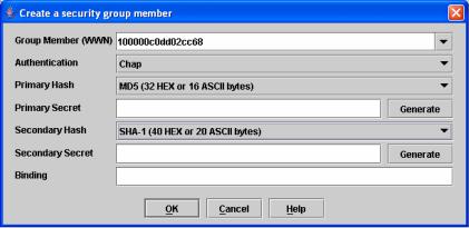
Create Security Group Member dialog
Use the Create Security Group Member dialog, shown in Figure 8, to add a member to a security group. Choose options from the Group Member (or manually enter a hex value) and Authentication drop-down lists, and enter values in the Secret and Binding (ISL groups only) fields.
Figure 8 Create a Security Group Member dialog
The conventions for ISL security group members are listed below:
•You can enter member World Wide Name (WWN), which must be 16 hex characters, or 23 characters with valid WWN format xx:xx:xx:xx:xx:xx:xx:xx.
•The authentication choices are None and CHAP (Challenge Handshake Authentication Protocol).
•The Secret field is disabled if authentication is set to None. If authentication is CHAP, the Secret field is enabled. The secondary hash and secret are not supported when connecting to other McDATA products.
•Generate is only enabled when authentication is set to CHAP.
•Valid binding entries are 97–127.
26
The conventions for Port security group members are listed below:
•You can enter member World Wide Name (WWN), which must be 16 hex characters, or 23 characters with valid WWN format xx:xx:xx:xx:xx:xx:xx:xx.
•The authentication choices are None and CHAP.
•The Secret field is disabled if authentication is set to None. If authentication is CHAP, the Secret field is enabled. The secondary hash and secret are not supported when connecting to other McDATA products.
•Generate is only enabled when authentication is set to CHAP.
The conventions for MS security group members are listed below:
•You can enter member World Wide Name (WWN), which must be 16 hex characters, or 23 characters with valid WWN format xx:xx:xx:xx:xx:xx:xx:xx.
•The CT (common transport) authentication choices are None, MD5, and SHA-1.
•The Secret field is disabled if authentication is set to None, otherwise the Secret field enabled.
•Generate is only enabled when authentication is CHAP.
•Secret is 16 byte length for MD5 authentication, and 20 bytes if authentication is SHA-1.
To add a member to a security group:
1.Choose one of the following to open the Edit Security dialog from the faceplate display:
•Click Security on the tool bar.
•Select Security > Edit Security.
2.Choose one of the following to open the Create a Security Group Member dialog:
•Click a security group in the graphic window of the Edit Security dialog. Click Security Member in the tool bar.
•Right-click on a security group in the graphic window of the Edit Security dialog. Select Create Members from the popup menu.
3.Open the Group Member drop-down list and select a Node World Wide Name. The switch must be a member of any group in which authentication is used. You can also enter a hex value.
4.Open the Authentication drop-down list, and select a type of protocol to be used for the authentication process for that member.
•ISL authentication options are None (0 bytes), CHAP (16 bytes)
•MS (CT—Common Transport) authentication options are None (0 bytes), MD5 (16 bytes), SHA (20 bytes)
•Port authentication options are None (0 bytes), CHAP (16 bytes)
5.Enter an authentication password to be assigned that member in the Secret area. Or, click Generate to randomly generate a secret.
6.Enter the domain ID (97–127) for the switch for the ISL group member in the Binding field (ISL groups only). The WWN of the switch must be at the entered domain ID when attempting to enter the fabric, otherwise it will become isolated.
7.Click OK to save the changes.
McDATA® 4Gb SAN Switch for HP p-Class BladeSystem user guide 27
Editing the security configuration on a switch
To edit a security configuration on the switch from the faceplate display:
1.Choose one of the following to open the Edit Security dialog:
•Click Security on the tool bar.
•Select Security > Edit Security.
By default, the security configuration on the switch is displayed in the Edit Security dialog.
2.Choose one of the following from the Edit Security dialog:
•Select File > Open File. Browse for and select the security file.
•Press Control+O (letter o). Browse for and select the security file.
3.Click Open to display the security file in the Edit Security dialog.
4.Select the security item to edit in the graphic window, and choose one of the following:
•Rename a security set, or group. Select a rename option from the Edit menu. Enter a new name in the Rename dialog. Click OK to save the changes.
•Edit security group member. Select an Edit Security Group Member option from the Edit menu. Enter
a new Group Member (WWN) in the Edit Security Group Member dialog. Choose an option in the Authentication drop-down list. Click OK to save the changes.
•Remove a security set, group, or member. Select the item to remove, and select a remove option from the Edit menu. Click OK in the Remove dialog to remove that item from the security file and save the changes.
•Clear security. Select the Security Sets directory name. Select Edit > Clear Security. Click OK in the
Remove dialog to remove all security sets and save the changes. You can also right-click on the Security Sets (top level) directory name, select Clear Security from the popup menu, and click OK to remove all security sets.
5.To save the changes, choose one of the following:
•Click Apply to save the changes and keep the Edit Security dialog open. Click OK to close the Edit Security dialog.
•Click OK to save changes and close the Edit Security dialog.
Viewing properties of a security set, group, or member
To view the properties of a security set, group, or member from the faceplate display:
1.Click Security on the tool bar, or select Security > Edit Security to open the Edit Security dialog.
2.Choose one of the following:
•Click a security set, security group, or security group member. Select Edit > Properties.
•Right-click on a security item In the graphic window. Select Properties from the popup menu.
3.View the security information for the selected item in the Properties dialog.
4.Click OK to close the dialog.
28

Security Config dialog
Use the Security Config dialog, shown in Figure 9, to save the active security configuration on the switch to non-volatile or to temporary memory, and to require the domain ID of a switch be validated before attaching to the fabric.
Figure 9 Security Config dialog
To configure switch security from the faceplate display:
1.Select Security > Edit Security Config to open the Security Config dialog.
2.Select the Auto Save option to enable (default) or disable Auto Save mode.
If enabled, the security configuration is saved to non-volatile memory on the switch. If disabled, the security file is saved only to temporary memory. The Auto Save feature is used when Fabric Binding is enabled. When Auto Save is disabled, any updates from remote switches will not be saved locally. If the local switch is reset, it may isolate.
3.Select the Fabric Binding Enabled option to require the expected domain ID of a switch to be verified before being allowed to attach to the fabric.
NOTE: The fabric binding feature must be enabled on all switches in the fabric. When enabling this feature, it is best to set the switch state to offline, enable the fabric binding feature on all switches, and then set the switch state to online.
4. Click OK to save the settings and close the Security Config dialog.
Archiving a security configuration to a file
To archive (save) a security configuration to a file from the faceplate display:
1.Click Security on the tool bar, or select Security > Edit Security to open the Edit Security dialog.
2.Make desired changes to the security settings using the security dialogs.
3.Select File > Save As.
4.Enter a name and location for the security file (.xml extension) in the Save dialog.
5.Click Save to save the security file.
Activating a security set
Only one security set can be active at one time. To activate a security set from the faceplate display:
1.Select Security > Activate Security Set to open the Activate Security Set dialog.
2.Select a security set from the drop-down list.
3.Click Activate to activate the security set.
McDATA® 4Gb SAN Switch for HP p-Class BladeSystem user guide 29
Deactivating a security set
Only one security set can be active at one time. To deactivate an active security set from the faceplate display:
1.Select Security > Deactivate Security Set.
2.Select a security set from the drop-down list in the Deactivate Security Set dialog.
3.Click Yes to confirm that you want to deactivate the active security set in the Deactivate Security Set dialog.
Configured Security data window
The Configured Security data window displays a graphical representation of all security sets, security groups, and security group members in the database. Click the Configured Security data window tab in
the faceplate display to open the Configured Security data window.
Active Security data window
The Active Security data window displays a graphical representation of the active security set, its groups, and members in the database. Click the Active Security data window tab in the faceplate display to open
the Active Security data window.
Fabric services
Fabric services security includes Simple Network Management Protocol (SNMP) and in-band management. SNMP is the protocol governing network management and monitoring of network devices. SNMP security consists of a read community string and a write community string, that are basically the passwords that control read and write access to the switch. The read community string ("public") and write community string ("private") are set at the factory to these well-known defaults and should be changed if SNMP is enabled using the System Services or SNMP Properties dialogs. If SNMP is enabled (default) and the read and write community strings have not been changed from their defaults, you risk unwanted access to the switch. See ”Enabling SNMP configuration” on page 30 for more information. SNMP is enabled by default.
In-band management is the ability to manage switches across Inter-switch Links (ISL) using McDATA Web Server, SNMP, management server, or the application programming interface. The switch comes from the factory with in-band management enabled. If you disable in-band management on a particular switch, you can no longer communicate with that switch by means other than an Ethernet connection. See ”Enabling in-band management” on page 30 for more information.
Enabling SNMP configuration
To enable SNMP configuration from the faceplate display:
1.Select Switch > SNMP Properties to open the SNMP Properties dialog.
2.Select the SNMP Enabled option in the SNMP Configuration area.
3.Click OK to save the change to the database.
Enabling in-band management
To enable in-band management from the faceplate display:
1.Select Switch > Switch Properties to open the Switch Properties dialog.
2.Select the In-band Management Enable option.
3.Click OK to save the change to the database.
Rediscovering a fabric
After making changes to or deleting switches from a fabric view, it may be helpful to again view the actual fabric configuration. The Rediscover Fabric option clears out the current fabric information being displayed, and rediscovers all switch information. Select Fabric > Rediscover Fabric to rediscover a fabric. The
rediscover function is more comprehensive than the refresh function.
30
Loading...