


LASERJET PRO 200 COLOR
Repair Manual
M251n |
M251nw |

HP LaserJet Pro 200 color M251 Series Printer
Repair Manual
Copyright and License
© 2012 Copyright Hewlett-Packard
Development Company, L.P.
Reproduction, adaptation, or translation without prior written permission is prohibited, except as allowed under the copyright laws.
The information contained herein is subject to change without notice.
The only warranties for HP products and services are set forth in the express warranty statements accompanying such products and services. Nothing herein should be construed as constituting an additional warranty. HP shall not be liable for technical or editorial errors or omissions contained herein.
Part number: CF146-90961
Edition 1, 9/2012
Trademark Credits
Microsoft®, Windows®, Windows® XP, and Windows Vista® are U.S. registered trademarks of Microsoft Corporation.
ENERGY STAR and the ENERGY STAR mark are registered U.S. marks.

Conventions used in this guide

 TIP: Tips provide helpful hints or shortcuts.
 NOTE: Notes provide important information to explain a concept or to complete a task.
CAUTION: Cautions indicate procedures that you should follow to avoid losing data or damaging the product.
WARNING! Warnings alert you to specific procedures that you should follow to avoid personal injury, catastrophic loss of data, or extensive damage to the product.
ENWW |
iii |
iv |
Conventions used in this guide |
ENWW |

Table of contents
1 Removal and replacement ................................................................................................ |
1 |
Removal and replacement strategy ............................................................................................. |
2 |
Introduction .............................................................................................................. |
2 |
Removal and replacement strategy .............................................................................. |
2 |
Electrostatic discharge ............................................................................................... |
2 |
Required tools ........................................................................................................... |
3 |
Types of screws ........................................................................................................ |
4 |
Service approach ..................................................................................................................... |
4 |
Before performing service .......................................................................................... |
4 |
After performing service ............................................................................................. |
5 |
Post-service test ......................................................................................................... |
5 |
Print-quality test .......................................................................................... |
5 |
Parts removal order ................................................................................................... |
7 |
Removal and replacement procedures ........................................................................................ |
8 |
Rollers ..................................................................................................................... |
8 |
Pick roller .................................................................................................. |
8 |
Separation roller ...................................................................................... |
10 |
Transfer roller .......................................................................................... |
12 |
Toner-cartridge drawer ............................................................................................ |
14 |
Covers ................................................................................................................... |
15 |
Right cover .............................................................................................. |
15 |
Left cover ................................................................................................ |
18 |
Rear right cover ....................................................................................... |
21 |
Rear upper cover ..................................................................................... |
22 |
Rear door and rear lower cover ................................................................. |
23 |
Upper cover, LCD control panel products (HP LaserJet Pro 200 color M251n |
|
Printer) .................................................................................................... |
26 |
Upper cover, touchscreen control panel products (HP LaserJet Pro 200 color |
|
M251nw Printer) ...................................................................................... |
28 |
LCD control-panel assembly (HP LaserJet Pro 200 color M251n Printer) .......... |
31 |
Touchscreen control-panel assembly (HP LaserJet Pro 200 color M251nw |
|
Printer) .................................................................................................... |
32 |
ENWW |
v |
USB cover (touchscreen control-panel models) .............................................. |
34 |
Front-door and front-cover assembly ........................................................... |
35 |
Main assemblies ..................................................................................................... |
39 |
Paper-guide assembly ............................................................................... |
39 |
Driver PCA .............................................................................................. |
40 |
DC controller PCA .................................................................................... |
44 |
Special consideration ................................................................ |
44 |
Remove the DC controller PCA .................................................... |
45 |
Formatter PCA ......................................................................................... |
47 |
Special consideration ................................................................ |
47 |
Remove the formatter PCA .......................................................... |
47 |
Wireless PCA .......................................................................................... |
50 |
Main motor ............................................................................................. |
51 |
Intermediate transfer belt (ITB) .................................................................... |
52 |
Reinstall the ITB ......................................................................... |
54 |
High-voltage power supply ........................................................................ |
56 |
Low-voltage power supply ......................................................................... |
59 |
Fuser power supply .................................................................................. |
61 |
Fuser ...................................................................................................... |
64 |
Fan ........................................................................................................ |
66 |
2 Parts and diagrams ........................................................................................................ |
69 |
Order parts by authorized service providers .............................................................................. |
70 |
Order replacement parts .......................................................................................... |
70 |
Related documentation and software ......................................................................... |
70 |
Supplies part numbers ............................................................................................. |
70 |
Service parts .......................................................................................................... |
70 |
Whole-unit replacement part numbers ........................................................................ |
71 |
How to use the parts lists and diagrams .................................................................................... |
72 |
Assembly locations ................................................................................................................. |
73 |
Base product (no optional trays or accessories) ........................................................... |
73 |
Covers, panels, and doors ...................................................................................................... |
76 |
Internal assemblies ................................................................................................................. |
80 |
Alphabetical parts list ............................................................................................................. |
88 |
Numerical parts list ................................................................................................................ |
91 |
Index ................................................................................................................................. |
95 |
vi |
ENWW |

List of tables
Table 1-1 Common fasteners ................................................................................................................. |
4 |
Table 2-1 Order parts, accessories, and supplies .................................................................................... |
70 |
Table 2-2 Related documentation and software ...................................................................................... |
70 |
Table 2-3 Supplies part numbers ........................................................................................................... |
70 |
Table 2-4 Service parts ........................................................................................................................ |
70 |
Table 2-5 Whole-unit replacement part numbers ..................................................................................... |
71 |
Table 2-6 LCD model .......................................................................................................................... |
73 |
Table 2-7 Touchscreen control-panel model ............................................................................................ |
74 |
Table 2-8 Covers, panels, and doors—network model ............................................................................. |
77 |
Table 2-9 Covers, panels, and doors—network wireless model ................................................................ |
79 |
Table 2-10 Internal components (1 of 4) ................................................................................................ |
81 |
Table 2-11 Internal components (2 of 4) ................................................................................................ |
83 |
Table 2-12 Internal components (3 of 4) ................................................................................................ |
85 |
Table 2-13 Internal components (4 of 4) ................................................................................................ |
87 |
Table 2-14 Alphabetical parts list ......................................................................................................... |
88 |
Table 2-15 Numerical parts list ............................................................................................................. |
91 |
ENWW |
vii |
viii |
ENWW |
List of figures
Figure 1-1 Phillips and Pozidriv screwdriver comparison ............................................................................ |
3 |
Figure 1-2 Parts-removal order ................................................................................................................ |
7 |
Figure 1-3 Remove the pickup roller ........................................................................................................ |
9 |
Figure 1-4 Remove the separation roller (1 of 2) ..................................................................................... |
10 |
Figure 1-5 Remove the separation roller (2 of 2) ..................................................................................... |
11 |
Figure 1-6 Remove the transfer roller (1 of 3) ......................................................................................... |
12 |
Figure 1-7 Remove the transfer roller (2 of 3) ......................................................................................... |
12 |
Figure 1-8 Remove the transfer roller (3 of 3) ......................................................................................... |
13 |
Figure 1-9 Remove the toner-cartridge drawer (1 of 2) ............................................................................. |
14 |
Figure 1-10 Remove the toner-cartridge drawer (2 of 2) ........................................................................... |
14 |
Figure 1-11 Remove the right cover (1 of 4) ........................................................................................... |
15 |
Figure 1-12 Remove the right cover (2 of4) ............................................................................................ |
16 |
Figure 1-13 Remove the right cover (3 of 4) ........................................................................................... |
16 |
Figure 1-14 Remove the right cover (4 of 4) ........................................................................................... |
17 |
Figure 1-15 Remove the left cover (1 of 4) ............................................................................................. |
18 |
Figure 1-16 Remove the left cover (2 of 4) ............................................................................................. |
19 |
Figure 1-17 Remove the left cover (3 of 4) ............................................................................................. |
19 |
Figure 1-18 Remove the left cover (4 of 4) ............................................................................................. |
20 |
Figure 1-19 Remove the rear right cover ................................................................................................ |
21 |
Figure 1-20 Remove the rear upper cover .............................................................................................. |
22 |
Figure 1-21 Remove the rear door and rear lower cover (1 of 5) .............................................................. |
23 |
Figure 1-22 Remove the rear door and rear lower cover (2 of 5) .............................................................. |
24 |
Figure 1-23 Remove the rear door and rear lower cover (3 of 5) .............................................................. |
24 |
Figure 1-24 Remove the rear door and rear lower cover (4 of 5) .............................................................. |
25 |
Figure 1-25 Remove the rear door and rear lower cover (5 of 5) .............................................................. |
25 |
Figure 1-26 Remove the upper cover (1 of 2) ......................................................................................... |
26 |
Figure 1-27 Remove the upper cover (2 of 2) ......................................................................................... |
27 |
Figure 1-28 Remove the upper cover (1 of 5) ......................................................................................... |
28 |
Figure 1-29 Remove the upper cover (2 of 5) ......................................................................................... |
29 |
Figure 1-30 Remove the upper cover (3 of 5) ......................................................................................... |
29 |
Figure 1-31 Remove the upper cover (4 of 5) ......................................................................................... |
30 |
Figure 1-32 Remove the upper cover (5 of 5) ......................................................................................... |
30 |
ENWW |
ix |
Figure 1-33 Remove the control-panel assembly ...................................................................................... |
31 |
Figure 1-34 Remove the touchscreen control-panel (1 of 2) ...................................................................... |
32 |
Figure 1-35 Remove the touchscreen control-panel (2 of 2) ...................................................................... |
33 |
Figure 1-36 Remove the USB cover (1 of 2) ............................................................................................ |
34 |
Figure 1-37 Remove the USB cover (2 of 2) ............................................................................................ |
34 |
Figure 1-38 Remove the front-door and front-cover assembly (1 of 6) ......................................................... |
35 |
Figure 1-39 Remove the front-door and front-cover assembly (2 of 6) ......................................................... |
36 |
Figure 1-40 Remove the front-door and front-cover assembly (3 of 6) ......................................................... |
36 |
Figure 1-41 Remove the front-door and front-cover assembly (4 of 6) ......................................................... |
37 |
Figure 1-42 Remove the front-door and front-cover assembly (5 of 6) ......................................................... |
37 |
Figure 1-43 Remove the front-door and front-cover assembly (6 of 6) ......................................................... |
38 |
Figure 1-44 Remove the paper-guide assembly (1 of 2) ........................................................................... |
39 |
Figure 1-45 Remove the paper-guide assembly (2 of 2) ........................................................................... |
39 |
Figure 1-46 Remove the driver PCA (1 of 8) ........................................................................................... |
40 |
Figure 1-47 Remove the driver PCA (2 of 8) ........................................................................................... |
40 |
Figure 1-48 Remove the driver PCA (3 of 8) ........................................................................................... |
41 |
Figure 1-49 Remove the driver PCA (4 of 8) ........................................................................................... |
41 |
Figure 1-50 Remove the driver PCA (5 of 8) ........................................................................................... |
42 |
Figure 1-51 Remove the driver PCA (6 of 8) ........................................................................................... |
42 |
Figure 1-52 Remove the driver PCA (7 of 8) ........................................................................................... |
43 |
Figure 1-53 Remove the driver PCA (8 of 8) ........................................................................................... |
43 |
Figure 1-54 Remove the DC controller PCA (1 of 2) ................................................................................ |
45 |
Figure 1-55 Remove the DC controller PCA (2 of 2) ................................................................................ |
46 |
Figure 1-56 Remove the formatter PCA (1 of 2) ...................................................................................... |
48 |
Figure 1-57 Remove the formatter PCA (2 of 2) ...................................................................................... |
49 |
Figure 1-58 Remove the wireless PCA ................................................................................................... |
50 |
Figure 1-59 Remove the main motor ...................................................................................................... |
51 |
Figure 1-60 Remove the ITB (1 of 3) ...................................................................................................... |
52 |
Figure 1-61 Remove the ITB (2 of 3) ...................................................................................................... |
53 |
Figure 1-62 Remove the ITB (3 of 3) ...................................................................................................... |
53 |
Figure 1-63 Reinstall the ITB (1 of 2) ..................................................................................................... |
54 |
Figure 1-64 Reinstall the ITB (2 of 2) ..................................................................................................... |
55 |
Figure 1-65 Remove the high-voltage power supply (1 of 4) ..................................................................... |
56 |
Figure 1-66 Remove the high-voltage power supply (2 of 4) ..................................................................... |
57 |
Figure 1-67 Remove the high-voltage power supply (3 of 4) ..................................................................... |
57 |
Figure 1-68 Remove the high-voltage power supply (4 of 4) ..................................................................... |
58 |
Figure 1-69 Reinstall the power supply (high voltage) .............................................................................. |
58 |
Figure 1-70 Remove the low-voltage power supply (1 of 3) ...................................................................... |
59 |
Figure 1-71 Remove the low-voltage power supply (2 of 3) ...................................................................... |
60 |
Figure 1-72 Remove the low-voltage power supply (3 of 3) ...................................................................... |
60 |
Figure 1-73 Remove the fuser power supply (1 of 4) ............................................................................... |
61 |
x |
ENWW |
Figure 1-74 Remove the fuser power supply (2 of 4) ............................................................................... |
62 |
Figure 1-75 Remove the fuser power supply (3 of 4) ............................................................................... |
62 |
Figure 1-76 Remove the fuser power supply (4 of 4) ............................................................................... |
63 |
Figure 1-77 Remove the fuser (1 of 3) ................................................................................................... |
64 |
Figure 1-78 Remove the fuser (2 of 3) ................................................................................................... |
65 |
Figure 1-79 Remove the fuser (3 of 3) ................................................................................................... |
65 |
Figure 1-80 Remove the fan (1 of 4) ...................................................................................................... |
66 |
Figure 1-81 Remove the fan (2 of 4) ...................................................................................................... |
66 |
Figure 1-82 Remove the fan (3 of 4) ...................................................................................................... |
67 |
Figure 1-83 Remove the fan (4 of 4) ...................................................................................................... |
67 |
Figure 2-1 LCD control-panel model (HP LaserJet Pro 200 color M251n Printer) .......................................... |
73 |
Figure 2-2 Touchscreen control-panel model (HP LaserJet Pro 200 color M251nw Printer) ............................ |
74 |
Figure 2-3 Covers, panels, and doors—network model ............................................................................ |
76 |
Figure 2-4 Covers, panels, and doors—network wireless model ............................................................... |
78 |
Figure 2-5 Internal components (1 of 4) ................................................................................................. |
80 |
Figure 2-6 Internal components (2 of 4) ................................................................................................. |
82 |
Figure 2-7 Internal components (3 of 4) ................................................................................................. |
84 |
Figure 2-8 Internal components (4 of 4) ................................................................................................. |
86 |
ENWW |
xi |
xii |
ENWW |

1 Removal and replacement
●Removal and replacement strategy
●Service approach
●Removal and replacement procedures
ENWW |
1 |

Removal and replacement strategy
Introduction
This chapter describes the removal and replacement of field-replaceable units (FRUs) only.
Replacing FRUs is generally the reverse of removal. Occasionally, notes and tips are included to provide directions for difficult or critical replacement procedures.
HP does not support repairing individual subassemblies or troubleshooting to the component level.
Note the length, diameter, color, type, and location of each screw. Be sure to return each screw to its original location during reassembly.
Incorrectly routed or loose wire harnesses can interfere with other internal components and can become damaged or broken. Frayed or pinched harness wires can be difficult to find. When replacing wire harnesses, always use the provided wire loops, lance points, or wire-harness guides and retainers.
Removal and replacement strategy
WARNING! Turn the product off, wait 5 seconds, and then remove the power cord before attempting to service the product. If this warning is not followed, severe injury can result, in addition to damage to the product. The power must be on for certain functional checks during troubleshooting. However, disconnect the power supply during parts removal.
Never operate or service the product with the protective cover removed from the laser/scanner assembly. The reflected beam, although invisible, can damage your eyes.
The sheet-metal parts can have sharp edges. Be careful when handling sheet-metal parts.
CAUTION: Do not bend or fold the flat flexible cables (FFCs) during removal or installation. Also, do not straighten pre-folds in the FFCs. You must fully seat all FFCs in their connectors. Failure to fully seat an FFC into a connector can cause a short circuit in a PCA.


 NOTE: To install a self-tapping screw, first turn it counterclockwise to align it with the existing thread pattern, and then carefully turn it clockwise to tighten. Do not overtighten. If a self-tapping screw-hole becomes stripped, repair the screw-hole or replace the affected assembly.


 TIP: For clarity, some photos in this chapter show components removed that would not be removed to


 service the product. If necessary, remove the components listed at the beginning of a procedure before proceeding to service the product.
Electrostatic discharge
|
CAUTION: |
|
Some parts are sensitive to electrostatic discharge (ESD). Look for the ESD reminder |
|
|||
|
|||
|
|
|
|
when removing product parts. Always perform service work at an ESD-protected workstation or mat, or use an ESD strap. If an ESD workstation, mat, or strap is not available, ground yourself by touching the sheet-metal chassis before touching an ESD-sensitive part.
Protect the ESD-sensitive parts by placing them in ESD pouches when they are out of the product.
2 |
Chapter 1 Removal and replacement |
ENWW |
Required tools
●#2 Phillips screwdriver with a magnetic tip and a 152 mm (6 in) shaft length
●Precision slotted screwdriver with a 1 mm (0.04 in) blade width


 NOTE: This fine-point tool is required to release the front-door pins. The width of the blade must be 2 mm (0.08 in) or less to be able to push the door pins out of the mounting holes.
●Small slotted screwdriver
●Needle-nose pliers
●ESD mat (if one is available)
●Penlight (optional)
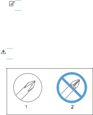
CAUTION: Always use a Phillips screwdriver (callout 1). Do not use a Pozidriv® screwdriver (callout 2) or any motorized screwdriver. These can damage screws or screw threads.
Figure 1-1 Phillips and Pozidriv screwdriver comparison
ENWW |
Removal and replacement strategy |
3 |
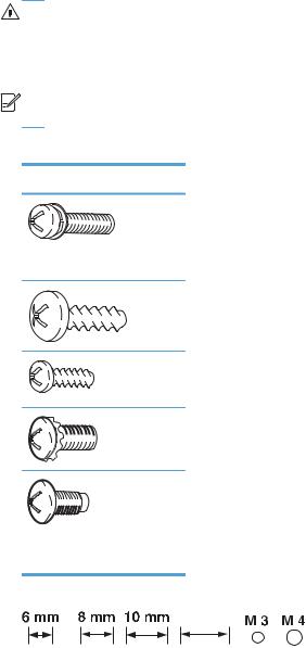
Types of screws
WARNING! Make sure that components are replaced with the correct screw type. Using the incorrect screw (for example, substituting a long screw for the correct shorter screw) can cause damage to the product or interfere with product operation. Do not mix screws that are removed from one component with the screws that are removed from another component.


 NOTE: The screw illustrations in the following table are for reference only. Screws might vary in size and appearance from those shown in this table.
Table 1-1 |
Common fasteners |
|
|
Example |
Description |
Size |
Part Number |
|
Screw, with washer |
M3X8 |
XA9-1420-000CN |
|
|
M4X6 |
XB2-7400-605CN |
|
|
M4X12 |
XA9-1422-000CN |
|
Screw, tapping, truss head |
M4X10 |
XB4-7401-005CN |
|
|
M4X15 |
XB4-7401-609CN |
|
Screw, TP |
M3X4 |
XB6-7300-405CN |
|
|
M3X6 |
XB6-7300-605CN |
|
Screw, D |
M3X6 |
XA9-1670-000CN |
|
|
M3X8 |
XA9-1671-000CN |
|
Screw, machine |
M3X4 |
XB6-7300-409CN |
|
Screw, machine, flat head |
M3X4 |
XA9-0679-000CN |
|
Screw, machine, flanged pan |
M3X6 |
XB6-7300-805CN |
|
head |
|
|
12 mm
Service approach
Before performing service
●Remove all paper from the product.
●Turn off the power using the power switch.
●Unplug the power cable and the interface cable or cables.
4 |
Chapter 1 Removal and replacement |
ENWW |
●Place the product on an ESD workstation or mat, or use an ESD strap (if one is available). If an ESD workstation, mat, or strap is not available, ground yourself by touching the sheet-metal chassis before touching an ESD-sensitive part.
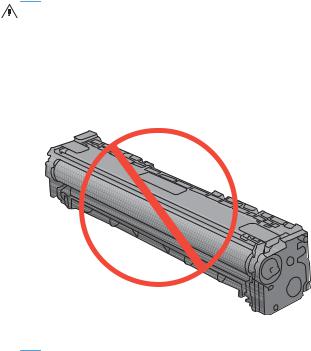
●Remove the toner cartridge.
CAUTION: Do not touch the imaging drum on the bottom of the toner cartridge. Finger prints on the imaging drum can cause print-quality problems.
Do not allow the image drum to contact any surface when the cartridge is set down. Protect the image drum at all times. Dust and debris can stick to the drum and cause print-quality problems.
After performing service
●Plug in the power cable.
●Reinstall the toner cartridge.
●Load paper in the product.
Post-service test
Perform the following test to verify that the repair or replacement was successful.
Print-quality test
1.Verify that you have completed the necessary reassembly steps.
2.Make sure that the tray contains clean, unmarked paper.
3.Attach the power cord and the interface cable or interface cables, and then turn on the product.
4.Verify that the expected startup sounds occur.
5.Print a configuration page, and then verify that the expected printing sounds occur.
6.Print a demo page, and then verify that the print quality is as expected.
ENWW |
Service approach |
5 |
7.Send a print job from the host computer, and then verify that the output meets expectations.
8.Clean the outside of the product with a damp cloth.
6 |
Chapter 1 Removal and replacement |
ENWW |
ENWW
Component |
|
Remove |
Remove |
Remove |
Remove |
Remove |
Remove |
Remove |
|||||||
|
|
|
|
|
|
|
|
|
|
|
|
|
|
|
|
Print cartridges |
|
|
|
|
|
|
|
|
|
|
|
|
|
|
|
Pickup roller |
Cassette assembly |
|
|
|
|
|
|
|
|
|
|
|
|
||
Separation roller |
Cassette assembly |
|
|
|
|
|
|
|
|
|
|
|
|
||
Transfer roller |
|
|
|
|
|
|
|
|
|
|
|
|
|
|
|
Print-cartridge drawer |
|
|
|
|
|
|
|
|
|
|
|
|
|
|
|
Right cover |
Cassette assembly |
|
|
|
|
|
|
|
|
|
|
|
|
||
Left cover |
Cassette assembly |
|
|
|
|
|
|
|
|
|
|
|
|
||
Rear-right cover |
Right cover |
|
|
|
|
|
|
|
|
|
|
|
|
||
Rear-upper cover |
Right cover |
Left cover |
Rear-right cover |
|
|
|
|
|
|
|
|
||||
Rear-door and rear-lower cover |
Right cover |
Left cover |
Rear-right cover |
|
|
|
|
|
|
|
|
||||
Upper-cover, LCD model |
Right cover |
Left cover |
Rear-right cover |
Rear-upper cover |
|
|
|
|
|
|
|||||
Upper-cover, touchscreen model |
Right cover |
Left cover |
Rear-right cover |
Rear-upper cover |
|
|
|
|
|
|
|||||
LCD control-panel |
Right cover |
Left cover |
Rear-right cover |
Rear-upper cover |
Upper cover |
|
|
|
|
||||||
Touchscreen control-panel |
Right cover |
Left cover |
Rear-right cover |
Rear-upper cover |
Upper cover |
|
|
|
|
||||||
USB cover (touchscreen CP model) |
Right cover |
Upper cover |
|
|
|
|
|
|
|
|
|
|
|||
Front-door and front-cover assembly |
Print cartridge drawer |
Left cover |
Right cover |
Rear-right cover |
Rear-door, rear-lower cover |
Rear-upper cover |
Upper cover |
||||||||
Paper-guide assembly |
|
|
|
|
|
|
|
|
|
|
|
|
|
|
|
Driver PCA |
Right cover |
|
|
|
|
|
|
|
|
|
|
|
|
||
DC controller PCA |
Right cover |
Upper cover |
|
|
|
|
|
|
|
|
|
|
|||
Formatter PCA |
Right cover |
|
|
|
|
|
|
|
|
|
|
|
|
||
Wireless PCA |
Right cover |
Formatter PCA |
|
|
|
|
|
|
|
|
|
|
|||
Main motor |
Right cover |
|
|
|
|
|
|
|
|
|
|
|
|
||
Intermediate transfer belt |
Print-cartridge drawer |
Right cover |
Left cover |
Rear-right cover |
Rear-door and rear-lower cover |
|
|
|
|
||||||
High-voltage power supply |
Right cover |
Left cover |
Rear-right cover |
Rear-upper cover |
Upper cover |
|
|
|
|
||||||
Low-voltage power supply |
Right cover |
Left cover |
Rear-right cover |
Rear-door and rear-lower cover |
|
|
|
|
|
|
|||||
Fuser power supply |
Right cover |
Left cover |
Rear-right cover |
Rear-door and rear-lower cover |
|
|
|
|
|
|
|||||
Fuser |
Right cover |
Left cover |
Rear-right cover |
Rear-upper cover |
Rear-door and rear-lower cover |
Upper cover |
|
|
|||||||
Fan |
Right cover |
|
|
|
|
|
|
|
|
|
|
|
|
||
approach Service
removal-Parts 2-1 Figure |
diagram following the Use |
order removal Parts |
order |
determine to |
|
|
.parts other removing before removed be must parts which |
|
7
Removal and replacement procedures
Rollers
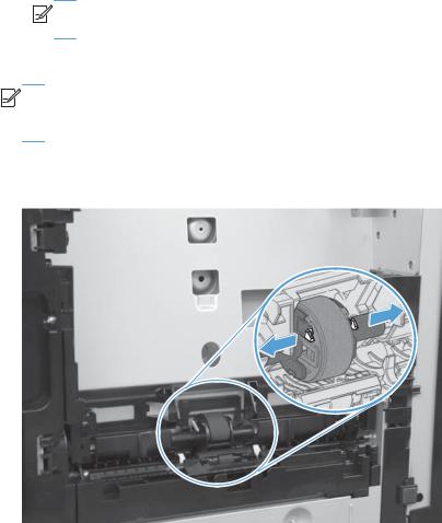
Pick roller
CAUTION: Do not touch the spongy roller surface unless you are going to replace the pick roller. Human skin oils that contact the pick roller can cause paper pickup problems.
1.Use the following procedures to rotate the pick roller into the position required to remove it.
LCD control panel (HP LaserJet Pro 200 color M251n Printer)
●Open the Secondary Service menu by pressing and releasing the Left arrow ( ) and then quickly pressing the Cancel button.
●Use the arrow buttons to select Pick roller, and then press the OK button.
●Press the OK button again to confirm that you want the pick roller to rotate.
●Remove the power cord, without turning off the power using the power switch, and then remove the interface cable.


 NOTE: If the power to the product is turned off using the power switch, the pick roller will rotate to the parked position.
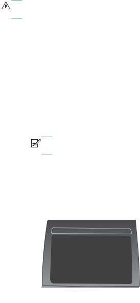
Touchscreen control panel (HP LaserJet Pro 200 color M251nw Printer)
●Touch the Setup  button.
●Touch the middle of the screen along the left edge (callout 1), and then immediately touch the lower-right corner (callout 2) of the screen.
1  2
2
●When the Home screen appears, touch the Setup  button again.
●Touch the 2ndary Service button.
●Touch the arrow buttons (at the right or left side of the touchscreen) until the Pick Roller button appears.
●Touch the Pick Roller button.
8 |
Chapter 1 Removal and replacement |
ENWW |
●Touch the OK button to confirm that you want the pick roller to rotate.
●Remove the power cord, without turning off the power using the power switch, and then remove the interface cable.


 NOTE: If the power to the product is turned off using the power switch, the pick roller will rotate to the parked position.
2.Remove the cassette assembly, and then carefully place the product front-side up.


 NOTE: Debris can scratch or damage the back of the product. Before you place the product front-side up, remove any debris from the work surface. If possible, set the product on a clean, dry cloth to prevent scratching and damage.
3.Release the two black plastic locking tabs and remove the pick roller.
Figure 1-3 Remove the pickup roller
ENWW |
Removal and replacement procedures |
9 |
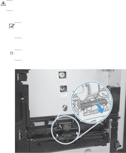
Separation roller
CAUTION: Do not touch the spongy roller surface unless you are going to replace the roller. Human skin oils that contact the roller can cause paper pickup problems.
1.Remove cassette (if installed), and then carefully place the product front-side up.


 NOTE: Debris can scratch or damage the back of the product. Before you place the product front-side up, remove any debris from the work surface. If possible, set the product on a clean, dry cloth to prevent scratching and damage.
2.Carefully release the roller cover and rotate it down and away from the roller.


 Reinstallation tip Make sure that this cover snaps into place over the roller when the roller


 and holder are reinstalled.
Figure 1-4 Remove the separation roller (1 of 2)
10 Chapter 1 Removal and replacement |
ENWW |
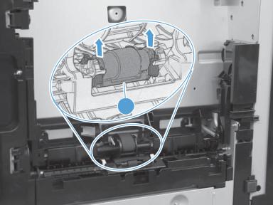
3.Use a small flat blade screwdriver to gently pry up on the roller and holder assembly (callout 1) to remove the roller and holder assembly.
Figure 1-5 Remove the separation roller (2 of 2)
1
ENWW |
Removal and replacement procedures 11 |
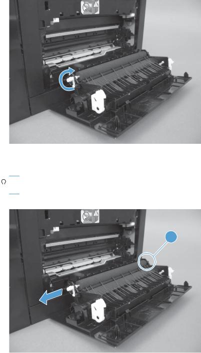
Transfer roller
1.Open the rear door.
2.Release the retainer clip and then rotate it until the pin on the clip aligns with the slot in the mounting bracket.
Figure 1-6 Remove the transfer roller (1 of 3)
3.Remove the clip. Repeat these steps for the remaining retainer clip (located at the opposite end of the roller shaft).


 TIP: One of the clips (callout 1) is made from a black conductive plastic. Make sure that the clips


 are reinstalled on the correct end of the transfer roller.
Figure 1-7 Remove the transfer roller (2 of 3)
1
12 Chapter 1 Removal and replacement |
ENWW |
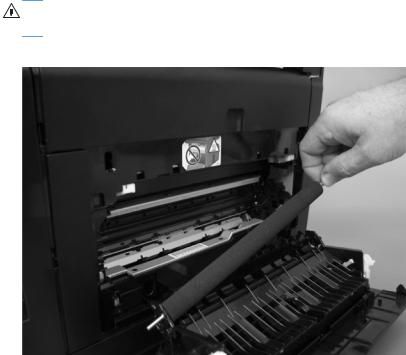
4.Slide the roller to one side to disengage the roller shaft from the mounting bracket, and then remove the transfer roller.
CAUTION: Do not touch the black sponge portion of the roller. Human skin oils that contact the roller can cause print-quality problems.
Figure 1-8 Remove the transfer roller (3 of 3)
ENWW |
Removal and replacement procedures 13 |

Toner-cartridge drawer
1.Open the front door and pull out the toner-cartridge drawer.

 TIP: This step is easier to perform, but not required, with the upper cover removed.
2.Release one tab (callout 1) with a flat blade screwdriver and remove the left cartridge-drawer stop (callout 2).
Figure 1-9 Remove the toner-cartridge drawer (1 of 2)
2
1
3.Release one tab (callout 1) with a flat blade screwdriver and remove the right cartridge-drawer stop (callout 2).
Figure 1-10 Remove the toner-cartridge drawer (2 of 2)
2
1
4.Remove the toner-cartridge drawer.
14 Chapter 1 Removal and replacement |
ENWW |
Covers
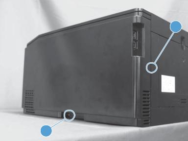
Right cover
1.Remove cassette assembly.
2.Open the front door.
3.Remove one screw (callout 1) and release two tabs (callout 2) using a flat blade screwdriver.
Figure 1-11 Remove the right cover (1 of 4)
 2
2
1
ENWW |
Removal and replacement procedures 15 |
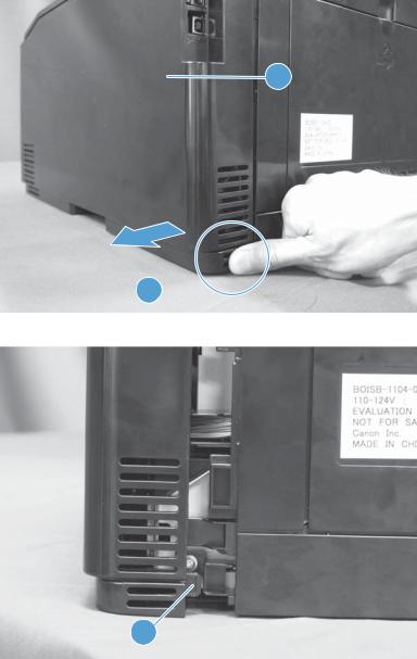
4.Push the right cover (callout 1) from the rear side (callout 2) and slide it away from the product to release one tab (callout 3).
Figure 1-12 Remove the right cover (2 of4)
1
2
Figure 1-13 Remove the right cover (3 of 4)
3
16 Chapter 1 Removal and replacement |
ENWW |
 Loading...