


ARMADASTATION
Compaq Armada 7000
Family of Personal Computers
INSTALLATION & OPERATIONS GUIDE
Notice
The information in this guide is subject to change without notice.
COMPAQ COMPUTER CORPORATION SHALL NOT BE LIABLE FOR TECHNICAL OR EDITORIAL ERRORS OR OMISSIONS CONTAINED HEREIN; NOR FOR INCIDENTAL OR CONSEQUENTIAL DAMAGES RESULTING FROM THE FURNISHING, PERFORMANCE, OR USE OF THIS MATERIAL.
This guide contains information protected by copyright. No part of this guide may be photocopied or reproduced in any form without prior written consent from Compaq Computer Corporation.
© 1998 Compaq Computer Corporation. All rights reserved. Printed in U.S.A.
Compaq and LTE are registered in the U.S. Patent and Trademark Office. Armada is a trademark of Compaq Computer Corporation.
Microsoft, MS-DOS, and Windows are registered trademarks of Microsoft Corporation.
The software described in this guide is furnished under a license agreement or nondisclosure agreement. The software may be used or copied only in accordance with the terms of the agreement.
Product names mentioned herein may be trademarks and/or registered trademarks of their respective companies.
ARMADASTATION
Compaq Armada 7000 Family of Personal Computers
Installation and Operations Guide
First Edition April 1998
Part Number 203118-001
Compaq Computer Corporation

CONTENTS
preface
USING THIS GUIDE ...................................................................................... |
xi |
chapter 1 |
|
GETTING STARTED |
|
Contents of the Packing Box............................................................ |
1-1 |
Removing the Keys from the PC Card Slot ..................................... |
1-2 |
Installation Requirements................................................................. |
1-3 |
Setting Up a Desktop System Without an External Monitor........... |
1-4 |
Connecting the Keyboard and Mouse ......................................... |
1-5 |
Connecting the Expansion Base Power Cord.............................. |
1-6 |
Docking the Computer................................................................. |
1-8 |
Turning On the System ................................................................ |
1-9 |
Setting Up a Desktop System with an External Monitor............... |
1-10 |
Installing the Monitor on a Monitor Support Cover ................. |
1-11 |
Connecting the Keyboard, Mouse, and Monitor ....................... |
1-12 |
Completing the Setup................................................................. |
1-13 |
chapter 2 |
|
IDENTIFYING COMPONENTS |
|
Left Side Component ....................................................................... |
2-1 |
Front and Top Components.............................................................. |
2-2 |
Right Side Components.................................................................... |
2-4 |
Rear Panel Components ................................................................... |
2-6 |
Regional Differences........................................................................ |
2-7 |
Contents v

chapter 3
GETTING CONNECTED
Connecting an External Device ....................................................... |
3-1 |
Selecting a Connector.................................................................. |
3-1 |
Connecting an External Device to the System............................ |
3-2 |
Using an External Device in the System ......................................... |
3-3 |
Audio Equipment ........................................................................ |
3-3 |
External Keyboard....................................................................... |
3-5 |
External Monitor or Overhead Projector..................................... |
3-5 |
Joystick or MIDI Device ............................................................. |
3-5 |
USB Equipment........................................................................... |
3-6 |
Connecting a Modem....................................................................... |
3-6 |
Connecting an RJ-11 Jack ........................................................... |
3-8 |
Connecting a 25-Pin Connector .................................................. |
3-8 |
Establishing an Infrared Link .......................................................... |
3-9 |
Linking with the Infrared Port................................................... |
3-10 |
Linking with an Optional External Infrared Transceiver.......... |
3-11 |
Connecting to an Ethernet Network .............................................. |
3-12 |
Connecting a Network Cable .................................................... |
3-13 |
Installing Network Drivers........................................................ |
3-14 |
chapter 4 |
|
DOCKING AND UNDOCKING |
|
Preparing to Dock the Computer ..................................................... |
4-1 |
When the Computer Is Running Windows 95 ............................ |
4-1 |
When the Computer Is Not Running Windows 95 ..................... |
4-2 |
Docking the Computer..................................................................... |
4-3 |
Managing System Power ................................................................. |
4-4 |
Turning On the System................................................................ |
4-4 |
Using the Power Switch .............................................................. |
4-4 |
Using the Suspend Button ........................................................... |
4-5 |
Undocking the Computer................................................................. |
4-6 |
Automatic Undocking of the Computer...................................... |
4-6 |
Manual Undocking of the Computer........................................... |
4-8 |
vi Contents

chapter 5
SECURING THE SYSTEM
Managing System Security .............................................................. |
5-1 |
Locking Components with the Keylock .......................................... |
5-2 |
Locking and Unlocking the Keylock........................................... |
5-3 |
Replacing a Missing Key............................................................. |
5-4 |
Attaching an Optional Cable Lock................................................... |
5-5 |
chapter 6 |
|
CHARGING BATTERY PACKS |
|
Charging a Battery Pack................................................................... |
6-1 |
Inserting a Battery Pack into a MultiBay......................................... |
6-2 |
Removing a Battery Pack from a MultiBay..................................... |
6-2 |
chapter 7 |
|
USING REMOVABLE DRIVES |
|
Customizing the Device Bays .......................................................... |
7-1 |
Caring for Removable Drives .......................................................... |
7-2 |
Adding Drives to the System ........................................................... |
7-3 |
Selecting Supported Drives ......................................................... |
7-3 |
Combining Drives........................................................................ |
7-4 |
Using Drive Adapters....................................................................... |
7-5 |
Selecting a Drive Adapter............................................................ |
7-5 |
Obtaining a Drive Adapter........................................................... |
7-6 |
Using a Drive Adapter ................................................................. |
7-7 |
Inserting a Drive or Drive Assembly into a MultiBay................... |
7-14 |
Removing a Drive or Drive Assembly from a MultiBay............... |
7-15 |
chapter 8 |
|
INSERTING AND REMOVING PC CARDS |
|
Adding a PC Card to the System ..................................................... |
8-1 |
Selecting a PC Card Slot .................................................................. |
8-2 |
Inserting a PC Card .......................................................................... |
8-2 |
Removing a PC Card........................................................................ |
8-4 |
chapter 9 |
|
INSTALLING AND REMOVING AN EXPANSION BOARD |
|
Installing an Expansion Board ......................................................... |
9-1 |
Removing an Expansion Board........................................................ |
9-9 |
Contents vii

chapter 10
INSTALLING AND REMOVING A HALF-HEIGHT BAY DEVICE
Installing a Half-Height Bay Device ............................................. |
10-1 |
Removing a Half-Height Bay Device.......................................... |
10-16 |
chapter 11 |
|
SETTING UP A TOWER SYSTEM |
|
Preparing to Convert a Desktop System to a Tower System ........ |
11-2 |
Inserting the Desktop Expansion Base |
|
into an Optional Tower Stand........................................................ |
11-3 |
Docking the Computer in a Tower System ................................... |
11-4 |
Adjusting the Width of an Optional Tower Stand .................... |
11-6 |
Completing the Setup..................................................................... |
11-9 |
chapter 12 |
|
TROUBLESHOOTING |
|
Quick Solutions Checklist ............................................................. |
12-2 |
Solving Audio Problems................................................................ |
12-3 |
Solving Battery Pack Charging Problems ..................................... |
12-4 |
Solving Docking and Undocking Problems .................................. |
12-5 |
Solving Expansion Board Problems .............................................. |
12-6 |
Solving External Device Installation Problems............................. |
12-7 |
Solving External Keyboard Problems ........................................... |
12-8 |
Solving External Monitor Problems .............................................. |
12-9 |
Solving External Pointing Device Problems ............................... |
12-11 |
Solving Infrared Problems ........................................................... |
12-13 |
Solving Modem Problems ........................................................... |
12-15 |
Solving PC Card Problems .......................................................... |
12-18 |
Solving Printer Problems ............................................................. |
12-19 |
Solving Removable Drive Problems ........................................... |
12-20 |
Solving USB Problems ................................................................ |
12-22 |
appendix A |
|
COMPAQ CUSTOMER SUPPORT.................................................................. |
A-1 |
appendix B |
|
REGULATORY NOTICES .............................................................................. |
B-1 |
appendix C |
|
ELECTROSTATIC DISCHARGE ...................................................................... |
C-1 |
viii Contents

appendix D
SPECIFICATIONS ...................................................................................... |
D-1 |
appendix E |
|
CONNECTOR PIN ASSIGNMENTS................................................................. |
E-1 |
INDEX ....................................................................................................... |
I-1 |
Contents ix

preface
USING THIS GUIDE
Some or all of the following format conventions are used in this guide to distinguish elements of text:
■Names of keys are shown in bold type as they appear on the keyboard, for example, Ctrl, Backspace, Tab.
■Keys that you should press at the same time are represented by the key names and the plus (+) symbol, for example,
Ctrl+Alt+Delete.
■Commands are presented in lowercase, bold type as shown here: install or a:\install.
■An arrow symbol is used to separate icons or menu options that you should select in succession, for example, click the Start buttonÆSettingsÆControl Panel.
■When you need to type information without pressing the Enter key, you are directed to “type” the information.
■When you need to type information and press the Enter key, you are directed to “enter” the information.
NOTE: Text set off in this manner presents commentary, sidelights, or interesting points of information.
IMPORTANT: Text set off in this manner presents clarifying information or specific instructions.
WARNING: Text set off in this manner indicates that failure to
!follow directions could result in bodily harm or loss of life.
CAUTION: Text set off in this manner indicates that failure to follow directions could result in damage to equipment or loss of information.
Using This Guide xi
chapter 1
GETTING STARTED
Contents of the Packing Box
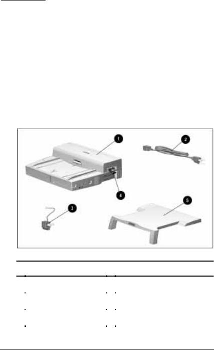
Before you begin, make sure you have removed everything from the box. In addition to the Quick Setup poster and documentation about the desktop expansion base, the box contains:
Contents of the Packing Box
Packing Box Contents
1Desktop expansion base |
4 Two expansion base keys |
|||||
|
|
|
|
|
(shipped inside PC Card slot) |
|
|
|
|
|
|
|
|
2 |
Expansion base power cord |
5 Monitor support cover (optional on |
||||
|
|
|
|
|
some models) |
|
|
|
|
|
|
|
|
3 |
3-to-2-prong plug adapter |
|
|
|
|
|
|
(Japan only) |
|
|
|
|
|
|
|
|
|
|
|
|
Getting Started 1-1

Removing the Keys from the PC Card Slot
To remove the two desktop expansion base keys from the PC Card slot, follow these steps:
1.Open the PC Card door 1 by swinging it upward from the bottom.
2.Slide the PC Card security post 2 toward the rear of the expansion base.
3.Remove the key carrier 3 and keys from the PC Card slot.
4.Close the PC Card door.
Removing the Keys from the PC Card Slot
1-2 Getting Started
Installation Requirements
The desktop expansion base can be used with any of the Compaq Armada 7000 Families of Personal Computers.
The expansion base and the computer can be set up as a desktop or tower system.
■A desktop system must include an external keyboard and mouse. For quick set up instructions, refer in this chapter to
“Setting Up a Desktop System Without an External Monitor”
or
“Setting Up a Desktop System with an External Monitor”
NOTE: A monitor support cover is included with some ArmadaStation models. To add a monitor support cover to your system as an optional accessory, refer to “Worldwide Telephone Numbers” in Appendix A to contact your nearest Compaq authorized dealer, reseller, or service provider.
■A tower system requires an optional tower stand. For quick setup instructions, refer to Chapter 11, “Setting Up a Tower System.”
Getting Started 1-3

Setting Up a Desktop System
Without an External Monitor
Desktop System without an External Monitor
1-4 Getting Started
Connecting the Keyboard and Mouse
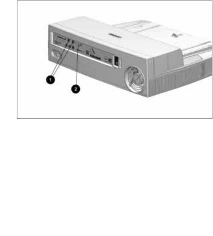
To connect the keyboard and mouse to the desktop expansion base, follow these steps:
1.Place the expansion base on a flat surface near an electrical outlet.
2.Connect the keyboard to one of the keyboard/mouse connectors 1.
3.If you have a PS/2-compatible mouse, connect it to the remaining keyboard/mouse connector. If you have a serial mouse, connect it to the serial connector 2.
NOTE: If you are not certain whether you have a PS/2-compatible or a serial mouse, refer to the documentation that came with
the mouse.
Identifying the Keyboard/Mouse Connectors and the Serial Connector on the Desktop Expansion Base
Getting Started 1-5
Connecting the Expansion Base Power Cord
To connect the desktop expansion base to electrical power, follow these steps:
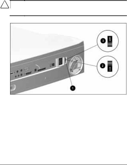
1.Set the voltage select switch 1 to the voltage supplied by your electrical service provider. When 115 VAC is selected 2, the number 115 is visible on the red portion of the switch. When 230 VAC is selected 3, the number 230 is visible.
NOTE: To verify the voltage of your electrical supply, contact your electrical service provider.
CAUTION: Ensure that the voltage select switch is in the correct position (115 VAC or 230 VAC). Failure to do so will result in damage to the equipment.
Setting the Voltage Select Switch
1-6 Getting Started
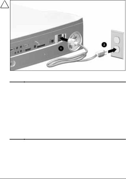
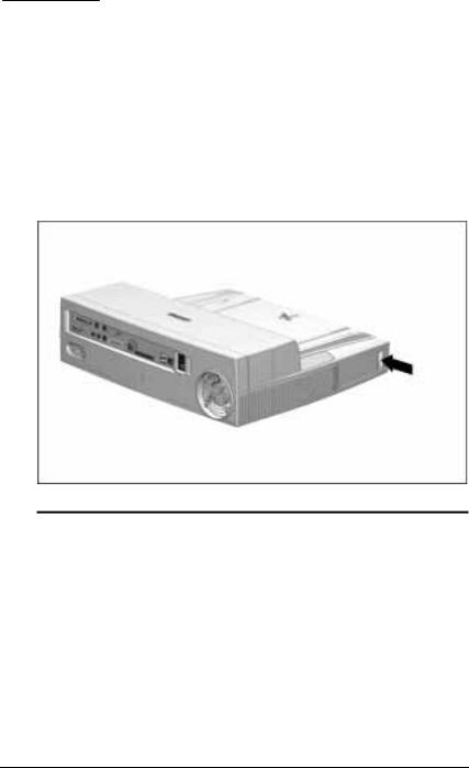
2.Plug the power cord into the power connector 1 on the expansion base, then into the electrical outlet 2.
NOTE: To plug the expansion base into an outlet in Japan, you you must first plug the power cord into the 3-to-2-prong plug adapter included with the expansion base. Ensure that the ground wire is connected to a safe earth ground, then plug the 3-to-2-prong plug adapter into the electrical outlet.
Plugging In the Desktop Expansion Base
WARNING: To reduce the risk of personal injury, electric shock,
!fire, or damage to the equipment:
■Do not disable the power cord grounding plug. The grounding plug is an important safety feature.
■Plug the equipment into a grounded (earthed) electrical outlet that is easily accessible at all times.
■Disconnect power from the equipment by unplugging the power cord from the electrical outlet.
■Do not place anything on power cords or cables. Arrange them so that no one may accidentally step on or trip over them. Do not pull on a cord or cable. When unplugging from the electrical outlet, grasp the cord by the plug.
Getting Started 1-7
Docking the Computer
! |
WARNING: To avoid the risk of personal injury, keep fingers and |
|
hands away from the rear of the computer when docking. |
||
|
|
|
|
CAUTION: Set up a new computer while it is undocked. Do not turn |
|
|
a computer on for the first time while it is docked. |
|
|
|
|
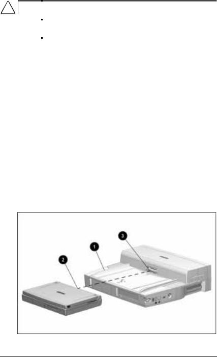
To dock the computer in the desktop expansion base, follow these steps:
1.Turn off the computer, if it is on. If you are not sure whether the computer is off or in Hibernation, turn the computer on, then shut it down.
NOTE: For information about docking the computer without shutting it down, refer to “Preparing to Dock the Computer” in Chapter 4.
2.Turn off, then disconnect any external equipment connected to the computer. Disconnect cables to any installed PC Cards. Disconnect the computer power cord.
3.Slide the computer into the expansion base along the left alignment guide 1.
4.Push the computer toward the rear of the expansion base until the docking connector on the computer 2 contacts the docking connector on the expansion base 3. This activates the motorized docking mechanism, which pulls the computer into a fully seated connection.
Docking the Computer in the Desktop Expansion Base
1-8 Getting Started
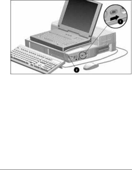
Turning On the System
To turn on power to the system (the desktop expansion base, computer, and connected external devices)
■Slide the power switch on the computer. or
■Slide the power switch 1 on the expansion base.
The power/suspend light 2 on the expansion base turns on when the system is on.
Turning On the System
Getting Started 1-9

Setting Up a Desktop System with an External Monitor
Desktop System with an Optional External Monitor
1-10 Getting Started

Installing the Monitor on a Monitor Support Cover
WARNING: To avoid the risk of personal injury or structural
!damage to the monitor support cover, do not place a monitor with an unstable base or a monitor heavier than 55 pounds (25 kilograms) on the support cover. Place the monitor on a work surface next to the docking base.
To install an optional external monitor on a monitor support cover, follow these steps:
1.Ensure that the monitor power switch is turned off.
2.Place the expansion base on a flat surface near an electrical outlet.
3.Place the monitor support cover on the desktop expansion base. Ensure that the legs 1 of the monitor support cover fit securely into the monitor support cover slots 2.
4.Place the base of the monitor on the flat area toward the rear of the monitor support cover.
Placing the Monitor Support Cover on the Desktop Expansion Base
Getting Started 1-11

Connecting the Keyboard, Mouse, and Monitor
To connect the keyboard, mouse, and monitor to the desktop expansion base, follow these steps:
1.Connect the keyboard to one of the keyboard/mouse connectors 1 on the rear panel of the expansion base.
2.If you have a PS/2-compatible mouse, connect it to the remaining keyboard/mouse connector. If you have a serial mouse, connect it to the serial connector 2.
NOTE: If you are not certain whether you have a PS/2-compatible or a serial mouse, refer to the documentation that came with the mouse.
3.Ensure that the power switch on the external monitor is off.
4.Connect the external monitor cable to the external monitor connector 3.
5.Plug the external monitor power cord into an electrical outlet.
Identifying the Keyboard/Mouse Connectors, Serial Connector, and External Monitor Connector on the Desktop Expansion Base
1-12 Getting Started
Completing the Setup
To complete the setup of a desktop system with an external monitor, follow these steps:
1.Turn off the computer, if it is on.
2.Close the computer, if it is open.
3.Follow the procedures in the previous section, “Setting Up the System Without an External Monitor,” for
■First, “Connecting the Expansion Base Power Cord.”
■Second, “Docking the Computer.”
■Third, “Turning On the System.”
4.Turn on the external monitor power switch.
Getting Started 1-13
chapter 2
IDENTIFYING COMPONENTS
Left Side Component
Left Side Component
|
Left Side Component |
|
Component |
Function |
|
|
|
|
Audio bass port |
Enhances sound. |
|
|
|
|
IMPORTANT: The audio bass port molded into the desktop expansion base is an active component of the expansion base audio system. Do not place foreign objects in this opening.
Identifying Components 2-1
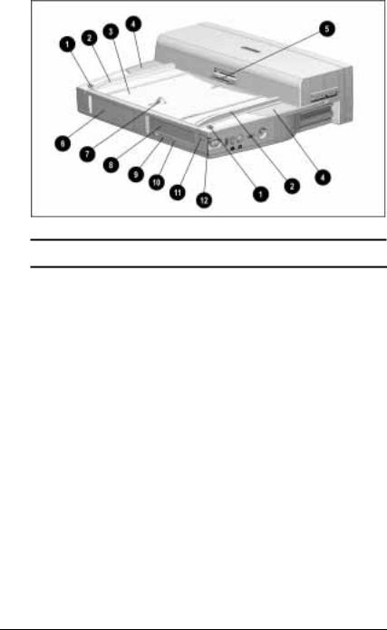
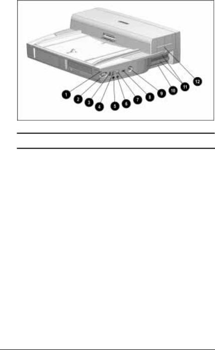
Front and Top Components
Front and Top Components
Front and Top Components
Component |
Function |
1 Monitor support cover |
Position monitor support cover. |
slots (2) |
|
|
|
2 Alignment guides (2) |
Guide computer during docking. |
|
|
3 Alignment tray |
Positions docked computer. |
|
|
4 Stereo speakers (2) |
Produce high quality stereo sound. |
|
|
5 Docking connector |
Connects to docking connector |
|
on computer. |
|
|
6 Half-height bay |
Supports a standard half-height bay |
|
device. Can be converted to a |
|
second MultiBay or an |
|
LTE 5000 MultiBay. |
|
|
7 Docking latch |
Helps secure computer in the |
|
expansion base. |
|
|
|
Continued |
2-2 Identifying Components

Front and Top Components Continued
Component |
Function |
8 MultiBay |
Supports any MultiBay device that is |
|
supported by a computer MultiBay. |
|
|
9 MultiBay device |
Releases a device from the MultiBay. |
release latch |
|
|
|
: MultiBay light |
Turns on when |
|
■ A removable drive in the MultiBay |
|
is being accessed. |
|
■ A battery pack in the MultiBay is |
|
charging. (Turns off when the |
|
battery pack is fully charged.) |
|
|
; Suspend button |
When system is off: Turns system on. |
|
When system is on: Initiates Suspend. |
|
When system is in Suspend: |
|
Exits Suspend. |
|
|
< Power/suspend light |
On: System is on. |
|
Off: System is off. |
|
Blinking: System is in Suspend. |
|
|
Identifying Components 2-3
Right Side Components
Right Side Components
Right Side Components
Component |
Function |
1 Power/suspend light |
On: System is on. |
|
Off: System is off. |
|
Blinking: System is in Suspend. |
|
|
2 Computer eject button |
Releases computer from the |
|
expansion base. |
|
|
3 Infrared port |
Links to another IrDA-compliant |
|
device for wireless communication. |
|
NOTE: This pass-through connector |
|
functions only when an infrared- |
|
equipped computer is docked. |
|
|
4 Volume control |
Adjusts volume on |
|
■ Expansion base speakers. |
|
■ Optional external speakers, |
|
headphone, or |
|
headset connected to the |
|
expansion base. |
|
|
|
Continued |
2-4 Identifying Components

Right Side Components Continued
Component |
Function |
5 Headphone jack |
Connects an optional stereo |
|
headphone or headset. |
|
|
6 Microphone jack |
Connects an optional single sound |
|
channel (monaural) microphone. |
|
|
7 Mute button |
Mutes volume on |
|
■ Expansion base speakers. |
|
■ Optional external speakers, |
|
headphone, or |
|
headset connected to the |
|
expansion base. |
|
|
8 Power switch |
When computer is docked, turns |
|
system power on and off. |
|
When computer is not docked, this |
|
button is disabled. |
|
|
9 Keylock |
When a computer is docked, |
|
can secure |
|
■ The computer to the |
|
expansion base. |
|
■ Removable drives and battery |
|
packs in expansion base and |
|
computer MultiBays. |
|
■ A battery pack in a computer |
|
battery bay. |
|
■ PC Cards in the expansion base. |
|
■ Options that are installed in the |
|
expansion base such as |
|
expansion boards or a |
|
100BaseTX Ethernet module. |
|
|
: Desktop expansion base |
Expansion base |
serial number |
identification number. |
|
|
; Expansion slot covers (2) |
Protect slots where optional |
|
expansion boards can be installed. |
|
|
< PC Card door |
Protects PC Card slots (2). |
|
|
Identifying Components 2-5
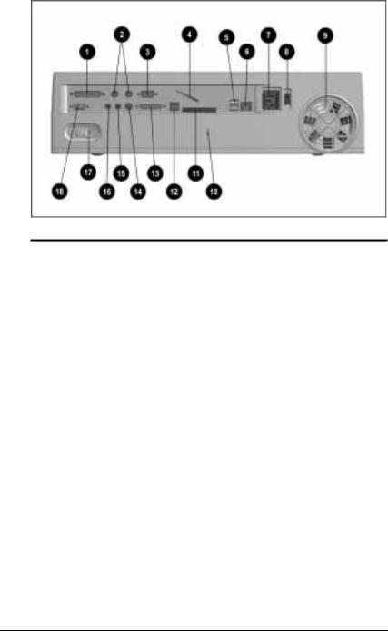
Rear Panel Components
Rear Panel Components
|
Rear Panel Components |
|
Component |
Function |
|
|
|
|
1 Parallel connector |
Connects an optional parallel device |
|
|
such as a parallel printer. |
|
|
|
|
2 Keyboard/mouse |
Connect an optional PS/2-compatible |
|
connectors (2) |
device such as a keyboard, mouse, |
|
|
or keypad. |
|
|
|
|
3 Serial connector |
Connects an optional serial device |
|
|
such as a serial mouse. |
|
|
|
|
4 U-bolt |
Attaches an optional security cable to |
|
|
the expansion base. Accommodates |
|
|
thicker cables than the security |
|
|
cable slot. |
|
|
|
|
5 USB connectors (2) |
Connect optional USB devices. |
|
|
NOTE: These USB pass-through |
|
|
connectors function only when a |
|
|
USB-equipped computer is docked. |
|
|
|
|
6 RJ-45 jack |
Connects a 10BaseT Ethernet |
|
|
network. Can be used with a |
|
|
100BaseTX Ethernet network if an |
|
|
optional 100BaseTX Ethernet Module |
|
|
is installed in the expansion base. |
|
|
|
|
7 Power connector |
Connects external AC power. |
|
|
|
|
|
Continued |
|
2-6 Identifying Components

Rear Panel Components Continued
Component |
Function |
8 Voltage select switch |
Adjusts expansion base to |
|
supplied voltage. |
|
|
9 Fan |
Circulates air through the expansion |
|
base to cool internal components. |
|
|
: Security cable slot |
Attaches an optional security cable to |
|
the expansion base. |
|
|
; 25-pin connector |
The availability and use of this pass- |
|
through modem connector varies |
|
regionally. Please refer to |
|
“Regional Differences” at the end of |
|
this chapter. |
|
|
< RJ-11 jack |
The availability and use of this pass- |
|
through modem connector varies |
|
regionally. Please refer to |
|
“Regional Differences” at the end of |
|
this chapter. |
|
|
= MIDI/game connector |
Connects an optional joystick or |
|
MIDI device. |
|
|
> External infrared transceiver |
Connects an optional External |
connector |
Infrared Transceiver. |
|
NOTE: This pass-through connector |
|
functions only when an infrared- |
|
equipped computer is docked. |
|
|
? Stereo line-in jack |
Connects an optional tape recorder, |
|
tuner, or CD player. |
|
|
@ Stereo line-out jack |
Connects optional external speakers. |
|
|
A Rear panel release latch |
Releases the rear panel of the |
|
expansion base, allowing access to |
|
the manual release latch and to |
|
internal components. |
|
|
B External monitor connector |
Connects an optional external |
|
monitor or overhead projector. |
|
|
Regional Differences
The desktop expansion base connectors used for modem passthrough vary by region.
■An expansion base purchased for use in North America, Latin America, Japan, or Hong Kong has an RJ-11 connector.
■An expansion base purchased for use in Europe or Asia Pacific (except Japan or Hong Kong) has a 25-pin connector.
Identifying Components 2-7
chapter 3
GETTING CONNECTED
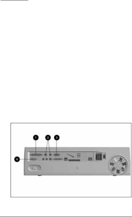
Connecting an External Device
Selecting a Connector
If the device documentation directs to you connect the device to a connector on the computer, you can connect the device to the connector with the same name on the desktop expansion base.
For example, if your printer, keyboard, mouse, numeric keypad, external monitor, or overhead projector documentation instructs you to connect the device to a parallel, PS/2, serial, or external monitor connector on your computer, you can connect the device to the parallel 1, keyboard/mouse (PS/2) 2, serial 3, or external monitor connector 4 on the expansion base.
Identifying Connectors
Getting Connected 3-1

Connecting an External Device to the System
To connect an external device to the system, follow these steps:
1.If the computer is docked turn it off.
2.If the external device is on, turn it off, then disconnect it from external power.
3.If the external device is connected to the computer, disconnect it.
4.Connect the external device cable to a connector on the expansion base.
5.If applicable, plug the power cord of the external device into an electrical outlet.
6.If applicable, turn on the power switch of the external device.
7.Turn on the system with the computer power switch or the expansion base power switch.
3-2 Getting Connected
 Loading...