


HercuLine® 2000 Series Actuator
Installation, Operation and
Maintenance Manual
Doc. No.: |
62-86-25-10 |
Revision: |
7 |
Date: |
7/08 |
Honeywell Field Solutions

Notices and Trademarks
Copyright 2008 by Honeywell
Revision 7 July 2008
Warranty/Remedy
Honeywell warrants goods of its manufacture as being free of defective materials and faulty workmanship. Contact your local sales office for warranty information. If warranted goods are returned to Honeywell during the period of coverage, Honeywell will repair or replace without charge those items it finds defective. The foregoing is Buyer's sole remedy and is in lieu of all other warranties, expressed or implied, including those of merchantability and fitness for a particular purpose. Specifications may change without notice. The information we supply is believed to be accurate and reliable as of this printing. However, we assume no responsibility for its use.
While we provide application assistance personally, through our literature and the Honeywell web site, it is up to the customer to determine the suitability of the product in the application.
CE Conformity
This product conforms with the protection requirements of the following European Council Directive: 89/336/EEC, the EMC directive and 73/23/EEC, the Low Voltage Directive. Conformance of this product with any other “CE Mark” Directive(s) shall not be assumed.
Attention
The emission limits of EN 50081-2 are designed to provide reasonable protection against harmful interference when this equipment is operated in an industrial environment. Operation of this equipment in a residential area may cause harmful interference. This equipment generates, uses, and can radiate radio frequency energy and may cause interference to radio and television reception when the equipment is used closer than 30 m to the antenna(e). In special cases, when highly susceptible apparatus is used in close proximity, the user may have to employ additional mitigating measures to further reduce the electromagnetic emissions of this equipment.
Honeywell Process Solutions
512 Virginia Drive
Fort Washington, PA 19034
HercuLink® and HercuLine® are trademarks of Honeywell
Palm is a trademark of Palm Inc.
Other brand or product names are trademarks of their respective owners.
ii |
HercuLine™ 2000 Series Actuator - Installation, Operation and Maintenance Manual |
Revision 7 |
|
|
7/08 |

About This Document
Abstract
This manual describes the installation, set up, operation, maintenance, and troubleshooting of the HercuLine 2000 series actuators.
References
The following list identifies all documents that may be sources of reference for material discussed in this publication.
|
Document Title |
Doc ID |
|
|
|
HercuLine 2000 |
Series Actuator Specification |
61-86-03-14 |
HercuLine 2000 |
Series Actuator Model Selection Guide |
62-86-16-21 |
Modbus® RTU Serial Communications User Manual |
51-52-25-66 |
|
Modbus® RTU Serial Communications User Manual |
51-52-25-103 |
|
Configuration/Remote Calibration Interfaces for HercuLine Actuators |
|
|
HercuLink™ User Manual |
62-86-25-11 |
|
HART Communications Installation and Operations Manual |
62-86-25-12 |
|
|
|
|
Contacts
World Wide Web
The following lists Honeywell’s World Wide Web sites that will be of interest to our customers.
Honeywell Organization |
WWW Address (URL) |
Corporate |
http://www.honeywell.com |
Honeywell Process Solutions |
http://www.honeywell.com/ps |
|
|
Telephone
Contact us by telephone at the numbers listed below.
|
Organization |
Phone Number |
|
United States and Canada |
Honeywell |
1-800-423-9883 |
Tech. Support |
|
|
1-800-525-7439 |
Service |
Revision 7 |
HercuLine™ 2000 Series Actuator - Installation, Operation and Maintenance Manual |
iii |
7/08 |
|
|
Symbol Definitions
The following table lists those symbols that may be used in this document to denote certain conditions.
Symbol |
Definition |
This DANGER symbol indicates an imminently hazardous situation, which, if not avoided, will result in death or serious injury.
This WARNING symbol indicates a potentially hazardous situation, which, if not avoided, could result in death or serious injury.
This CAUTION symbol may be present on Control Product instrumentation and literature. If present on a product, the user must consult the appropriate part of the accompanying product literature for more information.
This CAUTION symbol indicates a potentially hazardous situation, which, if not avoided, may result in property damage.
WARNING
PERSONAL INJURY: Risk of electrical shock. This symbol warns the user of a potential shock hazard where HAZARDOUS LIVE voltages greater than 30 Vrms, 42.4 Vpeak, or 60 Vdc may be accessible. Failure to comply with these instructions could result in death or serious injury.
ATTENTION, Electrostatic Discharge (ESD) hazards. Observe precautions for handling electrostatic sensitive devices
Protective Earth (PE) terminal. Provided for connection of the protective earth (green or green/yellow) supply system conductor.
Functional earth terminal. Used for non-safety purposes such as noise immunity improvement. NOTE: This connection shall be bonded to protective earth at the source of supply in accordance with national local electrical code requirements.
Earth Ground. Functional earth connection. NOTE: This connection shall be bonded to Protective earth at the source of supply in accordance with national and local electrical code requirements.
Chassis Ground. Identifies a connection to the chassis or frame of the equipment shall be bonded to Protective Earth at the source of supply in accordance with national and local electrical code requirements.
iv |
HercuLine™ 2000 Series Actuator - Installation, Operation and Maintenance Manual |
Revision 7 |
|
|
7/08 |

Contents
Contents
Introduction ............................................................................................. |
1 |
Product Description ...................................................................................................... |
1 |
Specifications .......................................................................................... |
5 |
Technical and Operating Specifications....................................................................... |
5 |
Model Selection Guide ............................................................................................... |
10 |
Installation ............................................................................................. |
12 |
Installation Overview .................................................................................................. |
12 |
Mechanical Stops ....................................................................................................... |
12 |
Before Starting............................................................................................................ |
13 |
Actuator Mounting ...................................................................................................... |
13 |
Mechanical Installation ............................................................................................... |
15 |
Electrical Installation................................................................................................... |
17 |
Burner Control/Flame Safety................................................................. |
23 |
Series 90 Control – HercuLine® 2001 model only...................................................... |
24 |
Split Range ................................................................................................................. |
26 |
Master/Slave Arrangement......................................................................................... |
26 |
Set Up and Calibration Procedures....................................................... |
31 |
Overview..................................................................................................................... |
31 |
Local Display and Keypad.......................................................................................... |
31 |
Set Up Tips................................................................................................................. |
33 |
Set Up Groups............................................................................................................ |
34 |
Set Up Procedure....................................................................................................... |
36 |
Configuration Prompt Hierarchy ................................................................................. |
38 |
Input Set Up Group..................................................................................................... |
39 |
Relays Set Up Group.................................................................................................. |
44 |
Current Out Set Up Group.......................................................................................... |
49 |
Communications Set Up Group.................................................................................. |
50 |
Digital Input Set Up Group ......................................................................................... |
51 |
Display Set Up Group................................................................................................. |
52 |
Revision 7 |
HercuLine™ 2000 Series Actuator - Installation, Operation and Maintenance Manual |
v |
7/08 |
|
|

Contents
Lock Set Up Group..................................................................................................... |
53 |
Read Status Set Up Group......................................................................................... |
55 |
Drive Set Up Group .................................................................................................... |
56 |
Maintenance Set Up Group........................................................................................ |
59 |
Regions of Motor Travel ............................................................................................. |
62 |
CAL POSOUT Group ................................................................................................. |
63 |
Auto - Manual Drive Switch ........................................................................................ |
64 |
Calibration .................................................................................................................. |
65 |
Setting End-of-Travel Limit Switches ......................................................................... |
78 |
Setting Auxiliary Switches .......................................................................................... |
81 |
Start-Up/Operation ................................................................................ |
83 |
Introduction................................................................................................................. |
83 |
Power-up Diagnostics................................................................................................. |
83 |
Operations Checklist .................................................................................................. |
83 |
Operating Displays ..................................................................................................... |
84 |
Motor Stall .................................................................................................................. |
84 |
Position Sensor Operation ......................................................................................... |
85 |
Remote Setpoint Operation........................................................................................ |
85 |
Maintenance.......................................................................................... |
87 |
Introduction................................................................................................................. |
87 |
Basic Maintenance ..................................................................................................... |
87 |
Replacement Procedures........................................................................................... |
89 |
Replacement/Upgrade/Accessory Kits.................................................. |
91 |
Replacement Kits ....................................................................................................... |
91 |
Upgrade Kits............................................................................................................. |
102 |
Accessory Kits .......................................................................................................... |
104 |
Troubleshooting .................................................................................. |
105 |
Introduction............................................................................................................... |
105 |
Troubleshooting Procedures .................................................................................... |
106 |
Appendix A - HercuLine® 2001/2002 Configuration Record Sheet...... |
112 |
Index ................................................................................................... |
116 |
vi |
HercuLine™ 2000 Series Actuator - Installation, Operation and Maintenance Manual |
Revision 7 |
|
|
7/08 |

|
|
Contents |
|
Tables |
|
Table 1 Specifications - General............................................................................................................................. |
5 |
|
Table 2 Recommended Minimum Wire Size........................................................................................................ |
17 |
|
Table 3 Terminal Connections: HercuLine® 2000............................................................................................... |
18 |
|
Table 4 Terminal Connections: HercuLine® 2001/2002 with auto/manual......................................................... |
19 |
|
Table 5 Split Range Set Up Procedure ................................................................................................................. |
26 |
|
Table 6 Keypad Description ................................................................................................................................. |
32 |
|
Table 7 Set Up Tips.............................................................................................................................................. |
33 |
|
Table 8 Set Up Groups ......................................................................................................................................... |
34 |
|
Table 9 Set Up Procedure Using Display and Keypad ......................................................................................... |
36 |
|
Table 10 Input Set Up Group Parameters............................................................................................................. |
39 |
|
Table 11 Equal Percentage Valve Characteristics ................................................................................................ |
42 |
|
Table 12 Quick Opening Valve Characteristic ..................................................................................................... |
43 |
|
Table 13 Relay Set Up Group Parameters ............................................................................................................ |
44 |
|
Table 14 Relay Type Descriptions........................................................................................................................ |
45 |
|
Table 15 Current Out Set Up Group Parameters .................................................................................................. |
49 |
|
Table 16 Communications Set Up Group Parameters .......................................................................................... |
50 |
|
Table 17 Digital Input Set Up Group Parameters................................................................................................. |
51 |
|
Table 18 Display Set Up Group Parameters......................................................................................................... |
52 |
|
Table 19 Lock Set Up Group Parameters ............................................................................................................. |
53 |
|
Table 20 Read Status Set Up Group Parameters .................................................................................................. |
55 |
|
Table 21 Drive Set Up Group Parameters ............................................................................................................ |
56 |
|
Table 22 Maintenance Set Up Group Parameters................................................................................................. |
59 |
|
Table 23 CAL POSOUT Group Parameters......................................................................................................... |
63 |
|
Table 24 Auto - Manual Switch Functions........................................................................................................... |
64 |
|
Table 25 Input Calibration Procedure................................................................................................................... |
69 |
|
Table 26 Motor Calibration Procedure ................................................................................................................. |
70 |
|
Table 27 Output Calibration Procedure................................................................................................................ |
71 |
|
Table 28 Slidewire Emulation Calibration Procedure .......................................................................................... |
73 |
|
Table 29 |
NCS Position Sensor Calibration Procedure......................................................................................... |
74 |
Table 30 |
Potentiometer Position Sensor Calibration Procedure.......................................................................... |
76 |
Table 31 Load Position Sensor Factory Calibration ............................................................................................. |
77 |
|
Table 32 End-of-Travel Limit Switch Setting Procedure ..................................................................................... |
79 |
|
Table 33 Auxiliary Switch Setting Procedure ...................................................................................................... |
82 |
|
Table 34 Typical Operating Displays ................................................................................................................... |
84 |
|
Table 35 Spur Gear Lubrication Procedure .......................................................................................................... |
87 |
|
Table 36 Motor Drive Fuse Replacment Procedure ............................................................................................. |
89 |
|
Table 37 Relay PWA Replacement Procedure ..................................................................................................... |
90 |
|
Table 38 Replacement kits.................................................................................................................................... |
96 |
|
Table 39 Observable Symptoms of Failure ........................................................................................................ |
105 |
|
Revision 7 |
HercuLine™ 2000 Series Actuator - Installation, Operation and Maintenance Manual |
vii |
7/08 |
|
|

Contents
Figures
Figure 1 HercuLine® 2000 Series Actuator |
2 |
Figure 2 HercuLine® 2002 Actuator Internal View |
3 |
Figure 3 Outline and Dimensions of HercuLine® 2000 Series Actuators |
14 |
Figure 4 Constant Torque Linkage |
15 |
Figure 5 Variable Torque Linkage |
16 |
Figure 6 Standard crank arm |
16 |
Figure 7 Crank arm with optional ball joint and push rod |
16 |
Figure 8 HercuLine® 2000 connections |
18 |
Figure 9 HercuLine® 2001/2002 connections |
19 |
Figure 10 HercuLine® 2003 connections |
20 |
Figure 11 CE wiring part 1 |
21 |
Figure 12 CE Wiring part 2 |
22 |
Figure 13 Burner Control/Flame Safety Wiring |
23 |
Figure 14 Series 90 connections |
24 |
Figure 15 T775 Controller connections |
25 |
Figure 16 Flow Diagram |
27 |
Figure 17 Interconnection Diagram |
27 |
Figure 18 Proportional Flow Using Multiple Actuators |
28 |
Figure 19 Multiple Actuator Interconnection Diagrams |
29 |
Figure 20 Interconnection Diagrams |
30 |
Figure 21 HercuLine® 2000 Display and Keypad |
31 |
Figure 22 Relay connectors |
46 |
Figure 23 Regions of Motor Travel |
62 |
Figure 24 Auto - Manual Switch |
64 |
Figure 25 Calibration Wiring Connections (non-slidewire emulation) |
66 |
Figure 26 Calibration Wiring Connections (slidewire emulation) |
67 |
Figure 27 Jumper Location on CPU PWA |
68 |
Figure 28 Location of NCS Assembly |
75 |
Figure 29 Location of potentiometer position sensor |
77 |
Figure 30 End of Travel Limit Switch Settings |
78 |
Figure 31 Location of End-of-Travel Limit and Auxiliary Switches |
80 |
Figure 32 Auxiliary Switch Settings |
81 |
Figure 33 Terminal Block Connections for Modbus Communications |
86 |
Figure 34 Spur Gear Location |
88 |
Figure 35 Power Distribution PWA and Relay PWA Locations |
89 |
Figure 36 Motor Drive Circuit Fuses |
90 |
Figure 37 Replacement Kits 6, 7, 8, 11, 12, 14 |
91 |
Figure 38 Replacement Kit 10 |
92 |
Figure 39 Replacement Kits 1, 2, 3, 4, 5, 9, 15, 16, 19 |
93 |
Figure 40 Replacement Kit 13 |
94 |
Figure 41 Replacement Kits 17, 18 |
95 |
Figure 42 Test for Actuator Operation |
107 |
Figure 43 Power Up Diagnostics |
108 |
Figure 44 Test Power Distribution PWA |
109 |
Figure 45 Test AUTO - MANUAL Switch |
110 |
Figure 46 Test Relay Function |
111 |
viii |
HercuLine™ 2000 Series Actuator - Installation, Operation and Maintenance Manual |
Revision 7 |
|
|
7/08 |

Introduction
Product Description
Introduction
Product Description
Honeywell’s HercuLine® 2000 series actuators are available in four versions: HercuLine® 2000,
HercuLine® 2001, HercuLine® 2002, and HercuLine® 2003. All are low torque, precision electric rotary actuators incorporating all of the high quality and reliable features of the traditional HercuLine series actuators. These precision control and high reliability actuators ensure processes operate at maximum efficiency, with minimal downtime, and lowest lifetime cost.
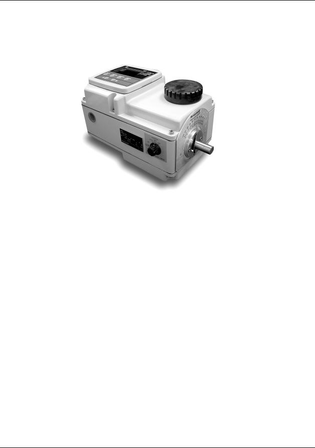
Honeywell's HercuLine® 2000 series actuators are precision engineered for exceptional reliability, accurate positioning, and low maintenance (Figure 1). Designed for very precise positioning of dampers and quarter turn valves the HercuLine® 2000 series actuators perform especially well in extremely demanding environments requiring continuous-duty, high reliability, and low maintenance.
Model distinctions
HercuLine® 2000 series actuators are used in applications requiring on/off or power to open/close position proportional with 135 or 1000 ohm feedback.
HercuLine® 2001 and 2002 are smart actuators used in applications requiring current proportional control or digital control. They offer digital electronics providing for precision positioning control, easy set-up and configuration, on board health monitoring, and network communications. Programming access is provided through our HercuLink® Palm PDA software connected to the actuator via a 232/485 converter, via HART communications or through the optional local keypad and display.
HercuLine® 2002 smart actuators offer features and functions similar to the HercuLine® 2001 and are used for more severe service applications requiring features such as non-contact position sensing.
HercuLine® 2003 actuators are unidirectional/ 360 degree rotation, special purpose actuators.
The keypad and display are available on the HercuLine® 2001 and HercuLine® 2002 products at additional charge.
HercuLink® Software
HercuLink® Computer software enables access to programming and communication functions available as standard with the HercuLine® 2001 and 2002 actuators without the added expense of the keypad & display HMI. Using a Palm™ PDA, laptop PC or desktop computer, HercuLink® software, and a RS232/485 converter users may configure, calibrate, and access maintenance information locally or remotely to the actuator.
Using HercuLink® software, the computer may be used as a master device over a Modbus network to access information to/from the actuators and to control the device. Set-up configurations may also be stored on the computer for download to other HercuLine® devices. Information may be stored on the users PC in CSV format for use in preventative maintenance programs.
•Certified on Palm™ m125, m130, and m505.
•Compatible with Palm OS3.5 or higher.
•Compatible with Windows 2000 or XP operating systems
•Minimum system requirements:
•Windows 2000 (w/service pack 2), Windows NT (w/service pack 5), Windows ME, Windows XP
•200 MHz Pentium with 64 Megs Ram
Revision 7 |
HercuLine™ 2000 Series Actuator - Installation, Operation and Maintenance Manual |
1 |
7/08 |
|
|
Introduction
Product Description
Display and
 keypad
Handwheel
Conduit entry
Shaft and position indicator
Auto/manual switch
Figure 1 HercuLine® 2000 Series Actuator
2 |
HercuLine™ 2000 Series Actuator - Installation, Operation and Maintenance Manual |
Revision 7 |
|
|
7/08 |
Introduction
Product Description
Display
Keypad
PWA
TB3 Connector for customer input and output connection on CPU PWA
Wiring
Label
 Mechanical Stops
Cams and limit switches
TB1 customer power connection
|
Non-contact |
External |
|
|
auto-manual |
||
Relay PWAs |
sensor |
||
switch |
|||
|
|
Figure 2 HercuLine® 2002 Actuator Internal View
Revision 7 |
HercuLine™ 2000 Series Actuator - Installation, Operation and Maintenance Manual |
3 |
7/08 |
|
|

Introduction
Product Description
4 |
HercuLine™ 2000 Series Actuator - Installation, Operation and Maintenance Manual |
Revision 7 |
|
|
7/08 |

Specifications
Technical and Operating Specifications
Specifications
This section provides you with the technical specifications and the model selection guide for the HercuLine® 2000 Series Actuators.
Technical and Operating Specifications
|
Table 1 Specifications - General |
|
|
||
|
|
|
|
|
|
|
Physical |
|
|
|
|
Weight |
2000: 25 lb. (11.36 kg) |
|
|
|
|
|
2001,2002: 27 lbs. (12.27 kg) |
|
|
|
|
|
|
|
|
||
Enclosure |
Precision-machined die cast aluminum housing, finished in light gray powder coat |
||||
|
epoxy. |
|
|
|
|
|
|
|
|
||
Gear Train |
Alloy steel, high efficiency steel spur gear primary train. Precision ground, self- |
||||
|
locking/self releasing worm gear final mesh. |
|
|
||
|
|
|
|
|
|
Mechanical Stops |
Factory set at 90° or 150° (+/-5°). |
|
|
|
|
|
Attention: Do not adjust the mechanical Stops. Adjusting the stops will void |
||||
|
the warranty |
|
|
|
|
|
|
|
|
|
|
Storage Temperature |
–40 °C to +93 °C (–40 °C to +200 °F) |
|
|
|
|
|
|
|
|
||
Relative Humidity |
0 % to 99 % R.H. non-condensing over the full operating temperature range. |
||||
|
|
|
|
|
|
Scale |
0 % to 100 % corresponding to full crank arm travel. |
|
|
||
|
|
|
|
||
Crank Arm |
Adjustable radii 1.0 in (25.4mm) to a maximum of 2.8 in (71.1mm). Position |
||||
|
adjustable through 360° rotation. |
|
|
|
|
|
|
|
|
|
|
Output Shaft |
0.625+/-.005 in (15.88 +/-.13mm) diameter |
|
|
||
|
|
|
|
||
Rotation |
90° or 150° degrees between 0 % and 100 % on scale, limited by mechanical stops. |
||||
Manual Handwheel |
Provides a means of positioning the actuator in the event of a power failure or set- |
||||
|
up. |
|
|
|
|
|
|
|
|
|
|
Lubrication |
Texaco Starplex 2 EP Grease |
|
|
|
|
|
|
|
|
|
|
Output Torque/Full |
Torque lb-in (N |
|
50 Hz (90°/150°) |
60 Hz (90°/150°) |
|
Travel Stroking Time |
M) |
|
4.5 / 7.5 |
4 / 6 |
|
|
50 / (6.0) |
|
9 / 15 |
7 / 12 |
|
|
100 / (11.5) |
|
18 / 30 |
15 / 25 |
|
|
200 / (22.5) |
|
36 / 60 |
30 / 50 |
|
|
|
54 / 90 |
|
||
|
400 / (45.0) |
|
45 / 75 |
|
|
|
|
|
|
||
|
400 / (45.0) |
|
|
|
|
Revision 7 |
HercuLine™ 2000 Series Actuator - Installation, Operation and Maintenance Manual |
5 |
7/08 |
|
|

Specifications
Technical and Operating Specifications
|
Electrical |
Mains Supply |
100-130 Vac single phase, 50 Hz or 60 Hz |
|
200-240 Vac single phase, 50 Hz or 60 Hz |
|
|
Motor |
Instant start/stop, non-coasting, non-burnout, continuous duty, permanent |
|
magnet, synchronous induction motor. Can be stalled up to 100 hours without |
|
damage. |
|
|
Motor Current |
= No load = full load = locked rotor = 0.4 amp for 120Vac, 0.2 amp for 240 Vac |
Loss of Power |
|
Stays in place on loss of power |
|
|
|
Local Auto/Manual Switch |
Optional – Allows local and automatic operation of the actuator. |
|
|
End of travel Limit |
Standard – adjustable to limit actuator travel to less than 90 or 150 degrees |
Switches |
respectively |
|
|
Auxiliary Switches/Relays |
Optional – Up to 4 additional SPDT switches rated at (10 A at 125 Vac, 5 A at 250 |
|
Vac). |
|
|
|
Certifications |
Approvals |
CSA/UL (Standard) |
|
CE Compliant (optional) |
|
|
Enclosure Rating |
Type 4 (NEMA 4), IP66 (standard) |
|
|
|
Torque Settings of Crank Arm Bolts |
Clamp Bolt |
88 lb-in (10 N-m) |
|
|
Electrical and Performance Specifications
|
HercuLine® 2002 |
HercuLine® 2001 |
HercuLine® 2000/2003 |
Input Signals |
Analog: |
Analog: |
|
|
• 0/4 to 20 mA (With CPU |
• 0/4 to 20 mA (With CPU |
120 vac drive open/120 vac |
|
PWA jumper in current |
PWA jumper in current |
drive close |
|
position) |
position) |
240 vac drive open/240 vac |
|
|
|
|
|
• 0/1 to 5 Vdc |
• 0/1 to 5 Vdc |
drive close |
|
• 0 to 10 Vdc |
• 0 to 10 Vdc |
|
|
Digital: |
• Series 90 control |
|
|
• Modbus RTU (RS485) |
Digital: |
|
|
|
• Modbus RTU (RS485) |
|
|
|
|
|
Isolation |
Input signal, output signal and power are isolated from each other. |
NA |
|
Load Requirement (4-20) |
Current Out — 0 to 1000 ohms |
|
NA |
Input Impedance |
0/4 to 20 mA |
250 ohms |
NA |
|
0/1 to 5 Vdc |
10 K ohms |
|
|
0-10 vdc |
|
|
Feedback |
0 to 20 mA, 4 to 20 mA |
|
Dual output 1000 ohms |
|
0 to 5 Vdc & 1 to 5 Vdc with 250 ohm resistor, (0 to 16 Vdc with 800 |
over 90 degrees (135 ohms |
|
|
with 158 resistor) |
||
|
ohm resistor) |
|
|
|
|
Dual output 1000 ohms |
|
|
|
|
|
|
|
|
over 150 degrees (135 |
|
|
|
ohms with with 158 resistor) |
6 |
HercuLine™ 2000 Series Actuator - Installation, Operation and Maintenance Manual |
Revision 7 |
|
|
7/08 |

Specifications
Technical and Operating Specifications
|
|
|
HercuLine® 2002 |
|
HercuLine® 2001 |
HercuLine® 2000/2003 |
|
Feedback |
Slidewire emulation - Provides |
|
|
|
|
|
|
|
output voltage ratiometric to |
|
|
|
|
|
|
shaft position and |
|
|
|
|
|
|
potentiometric to supply voltage |
|
|
|
|
|
|
(1 Vdc to 18 Vdc) without a |
|
|
|
|
|
|
slidewire. Emulates a 100 ohm |
|
|
|
|
|
|
to 1000 ohm slidewire. 10 mA |
|
|
|
|
|
|
output maximum. |
|
|
|
|
Communications |
Modbus RTU or optional HART™ |
NA |
|||
|
Operating Temperature |
–40°C to +75 °C (–40°F to +170 °F) |
|
-40°C to +85 °C (-40°F to |
||
|
|
|
|
|
|
+185 °F) |
|
Position sensing |
Non-contact position sensor |
|
1000 ohm film potentiometer |
Dual 1000 ohm film |
|
|
|
|
|
|
|
potentiometers |
|
|
|
|
|
|
(not on 2003) |
|
Sensitivity |
0.2 % to 5 % of 90° span, proportional to deadband |
NA |
|||
|
Hysteresis |
Less than 0.4 % of full scale |
|
|
NA |
|
|
Deadband |
0.2 % to 5 % of 90° span, programmable. Shipped at 0.5 % |
NA |
|||
|
Repeatability |
0.2 % of 90° span |
|
NA |
||
|
Repositions |
|
|
|
|
|
|
(minimum @ 90 or 150 |
|
|
|
|
|
|
degree stroke) |
|
|
|
|
|
|
Table 1 option –050- |
160 |
|
120 |
500 |
|
|
Table 1 option –100- |
290 |
|
250 |
|
|
|
Table 1 option –200- |
450 |
|
400 |
|
|
|
Table 1 option –400- |
700 |
|
400 |
|
|
|
Table 1 option –600- |
|
900 |
|
400 |
|
|
|
|
|
|
||
|
Voltage/ Supply |
0.25 % of span with +10/–15 % voltage change |
NA |
|||
|
Stability |
|
|
|
|
|
|
Temperature |
Less than ±0.030 % of span per degree C for 0 °C to 50 °C |
NA |
|||
|
Coefficient |
Less than ±0.05 % of span per degree C for –40 °C to 75 °C |
|
|||
|
|
|
|
|||
|
Zero Suppression |
90 % of span. |
|
NA |
||
|
Input Filters |
Selectable spike and low pass filters. |
NA |
|||
|
Solid State Motor |
Two triac switches for clockwise or anti-clockwise motor operation. |
NA |
|||
|
Control |
Transient voltage protection provided. |
|
|||
|
Failsafe operation |
If input signal exceeds configured input range. Selectable and |
NA |
|||
|
|
|
adjustable. |
|
|
|
|
Direction of Rotation |
Field programmable |
|
Wire swap |
||
|
Duty Cycle |
Continuous |
|
|
||
Revision 7 |
HercuLine™ 2000 Series Actuator - Installation, Operation and Maintenance Manual |
7 |
7/08 |
|
|

Specifications
Technical and Operating Specifications
|
|
|
|
HercuLine® 2002 |
|
HercuLine® 2001 |
|
HercuLine® 2000/2003 |
|
Programmable |
Selectable and configurable operating parameters: |
|
NA |
||||||
Functions |
|
|
|
|
|
|
|
|
|
|
|
• |
Input range |
|
|
|
|
||
|
|
• |
Input filtering |
|
|
|
|
||
|
|
• |
Input characterization |
|
|
|
|
||
|
|
• |
Security |
|
|
|
|
||
|
|
• |
Digital Input action |
|
|
|
|
||
|
|
• |
Deadband |
|
|
|
|
||
|
|
• Failsafe on loss of input signal |
|
|
|
|
|||
|
|
• Failsafe on loss of position sensor |
|
|
|
|
|||
|
|
• |
Direction of rotation |
|
|
|
|
||
|
|
• |
Relay closure action |
|
|
|
|
||
|
|
• |
Communication parameters |
|
|
|
|
||
|
|
• |
Split range operation |
|
|
|
|
||
|
|
• |
Output range |
|
|
|
|
||
|
|
• |
Alarms |
|
|
|
|
||
|
|
|
|
|
|
|
|
||
|
|
|
|
Specifications – Local Display and Keypad |
|
|
|||
|
|
|
|
|
|
|
|
|
|
|
|
|
|
Display |
|
|
|
|
|
|
Display Design |
|
|
Multi-segment LED displays that provides up to ten alphanumeric characters. Display |
|
||||
|
|
|
|
arrangement consists of two rows: |
|
|
|
|
|
|
|
|
|
1st row (Upper display) – four characters |
|
|
|||
|
|
|
|
2nd row (Lower display) – six characters. |
|
|
|||
|
LED indicators |
|
|
Six single LEDs provide actuator status and alarm indications. |
|
|
|||
|
|
|
|
|
|
|
|||
|
Display Operating |
|
|
-30 °C to +50 °C (-20 °F to +122 °F) |
|
|
|||
|
Temperature |
|
|
Automatically shuts off when operating temperature exceeds +50 °C |
|
||||
|
|
|
|
|
|
|
|||
|
Storage Temperature |
|
|
-40 °C to +93 °C (-40 °F to +200 °F) |
|
|
|||
|
|
|
|
|
|
|
|
|
|
|
|
|
|
Keypad |
|
|
|
|
|
|
Keys |
|
|
Six single pushbutton keys allow access to all status displays and set up group |
|
||||
|
|
|
|
parameters. |
|
|
|
|
|
|
|
|
|
|
|
|
|
|
|
See Set Up and Calibration Procedures (page 31) for detailed information on display and keypad functions.
8 |
HercuLine™ 2000 Series Actuator - Installation, Operation and Maintenance Manual |
Revision 7 |
|
|
7/08 |

|
|
Specifications |
|
|
Technical and Operating Specifications |
|
|
|
|
|
Specifications – Communications |
|
|
|
|
|
Communications |
|
Communications |
RS 485 Serial Communication, Modbus RTU Protocol |
|
Option |
|
|
|
|
|
Connection |
Twisted pair cable with shield |
|
|
|
|
Maximum loop length |
600 meters (2000 feet) |
|
|
|
|
Communication Mode |
Half duplex |
|
|
|
|
Baud Rate |
300, 600, 1200, 2400, 4800, 9600, 19.2K |
|
|
|
|
|
Required Specifications – PDA (customer provided) |
|
|
|
|
|
PDA |
|
Operating System |
Palm OS version 3.5 or greater |
|
|
|
|
RAM |
At least 8 MB |
|
|
|
|
Communications |
Serial port with RS232 compatible levels to drive external converter |
|
|
Note: As of this writing only Palm devices have this feature. Honeywell has qualified |
|
|
the M105, M125, M130, and M505 devices with the HercuLink application. |
|
|
|
Revision 7 |
HercuLine™ 2000 Series Actuator - Installation, Operation and Maintenance Manual |
9 |
7/08 |
|
|

Specifications
Model Selection Guide
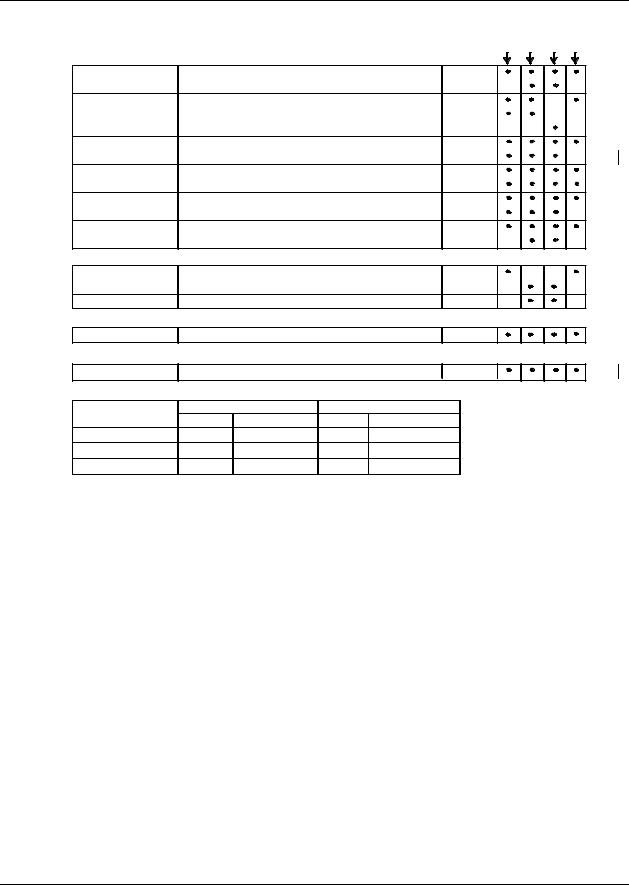
Model Selection Guide
Instructions
|
Select the desired key number. The arrow to the right marks the selection available. |
|
|
|
|
||||||||||||||||||
|
Make the desired selections from Tables I thru VIII using the column below the arrow. |
|
|
|
|
||||||||||||||||||
|
A dot ( ) denotes unrestricted availability. |
|
|
|
|
|
|
|
|
|
|
|
|
|
|
||||||||
|
Key Number |
|
I |
II |
|
III |
IV |
V |
|
VI |
|
VII |
VIII |
|
IX |
||||||||
|
_ _ _ _ |
|
- |
_ _ _ |
- |
_ _ _ |
- |
_ _ _ |
- |
_ _ _ |
- |
_ _ |
- |
_ _ _ _ _ _ |
- |
_ |
- |
_ |
- |
_ _ |
|
||
|
|
|
|
|
|
|
|
|
|
|
|
|
|
|
|||||||||
KEY NUMBER - Motor Selection |
|
|
|
|
|
|
|
|
|
|
Selection |
|
Availability |
||||||||||
Basic Motor Unit (no electronics) |
|
|
|
|
|
|
|
|
|
|
2000 |
|
|
|
|
||||||||
Basic Motor Unit plus Digital Electronics |
|
|
|
|
|
|
|
2001 |
|
|
|
|
|||||||||||
Enhanced Performance Motor Unit with Non-contact Position Sensing |
2002 |
|
|
|
|
||||||||||||||||||
Unidirectional Motor (M640D Replacement) |
|
|
|
|
|
|
|
2003 |
|
|
|
|
|||||||||||
TABLE I - TORQUE & SPEED SELECTION (speed per 150 degree rotation) |
|
|
|
|
|
|
|
||||||||||||||||
Torque, lb-in/(N-M) |
|
50Hz |
|
|
|
|
|
60Hz |
|
|
|
|
|
|
|
||||||||
50 / (6.0) |
|
|
|
|
7.5 sec |
|
|
|
|
|
6 sec |
050 |
|
|
|
|
|
||||||
100 / (11.5) |
|
|
|
15 sec |
|
|
|
|
|
12 sec |
100 |
|
|
|
|
|
|||||||
200 / 22.5) |
|
|
|
30 sec |
|
|
|
|
|
25 sec |
200 |
|
|
|
|
|
|||||||
400 / (45.0) |
|
|
|
60 sec |
|
|
|
|
|
50 sec |
400 |
|
|
|
|
|
|||||||
400 / (45.0) |
|
|
|
90 sec |
|
|
|
|
|
75 sec |
600 |
|
|
|
|
|
|||||||
TABLE II - ROTATION |
|
|
|
|
|
|
|
|
|
|
|
|
|
|
|
|
|
|
|||||
Travel |
|
|
|
90 degrees |
|
|
|
|
|
|
|
090 |
|
|
|
|
|
||||||
|
|
|
|
|
|
150 degrees |
|
|
|
|
|
|
|
150 |
|
|
|
|
|
||||
|
|
|
|
|
|
360 degrees |
|
|
|
|
|
|
|
360 |
|
|
|
|
|
||||
TABLE III - POWER SUPPLY |
|
|
|
|
|
|
|
|
|
|
|
|
|
|
|
|
|
||||||
Single Phase |
100 - 130 Vac, 60 Hz |
|
|
|
|
|
|
|
126 |
|
|
|
|
|
|||||||||
|
|
|
|
|
|
100 - 130 Vac, 50 Hz |
|
|
|
|
|
|
|
125 |
|
|
|
|
|
||||
|
|
|
|
|
|
200 - 240 Vac, 60 Hz |
|
|
|
|
|
|
|
246 |
|
|
|
|
|
||||
|
|
|
|
|
|
200 - 240 Vac, 50 Hz |
|
|
|
|
|
|
|
245 |
|
|
|
|
|
||||
TABLE IV - ANALOG INPUT/OUTPUT SIGNALS |
|
|
|
|
|
|
|
|
|
|
|
|
|
|
|||||||||
Input |
|
|
|
3 Wire Drive up/down |
|
|
|
|
|
|
|
0 _ _ |
|
|
|
|
|||||||
|
|
|
|
|
|
0/4-20 mA, 0/1-5 Vdc, 0-10 Vdc |
|
|
|
2 _ _ |
|
|
|
|
|||||||||
|
|
|
|
|
|
0/4-20 mA, 0/1-5 Vdc, 0-10 Vdc |
|
|
|
3 _ _ |
|
|
|
|
|||||||||
|
|
|
|
|
|
0 to 135 ohm input (Series 90 control) |
4 _ _ |
|
a |
|
|
||||||||||||
|
|
|
|
|
|
Contact Input for 2003 |
|
|
|
|
|
|
|
6 _ _ |
|
|
|
|
|||||
Output |
|
|
|
None |
|
|
|
|
|
|
|
|
|
|
_ 00 |
|
|
|
|
||||
|
|
|
|
(Note 1) |
Dual 1000 Ohm (1000 ohms over 150 degrees) |
_ 15 |
b |
|
|
|
|||||||||||||
|
|
|
|
(Note 1) |
Dual 1000 Ohm (1000 ohms over 90 degrees) |
_ 19 |
c |
|
|
|
|||||||||||||
|
|
|
|
|
|
Slidewire Emulation |
|
|
|
|
|
|
|
_ 60 |
|
|
|
|
|||||
|
|
|
|
|
|
Slidewire Emulation |
|
|
|
|
|
|
|
_ 65 |
|
|
|
|
|||||
|
|
|
|
|
|
0/4-20mAdc (0/1-5 Vdc, 0-16 Vdc) |
|
|
|
_ 80 |
|
|
|
|
|||||||||
|
|
|
|
|
|
0/4-20mAdc (0/1-5 Vdc, 0-16 Vdc) |
|
|
|
_ 85 |
|
|
|
|
|||||||||
TABLE V - SWITCH AND RELAY OUTPUTS (2 end-of-travel switches are standard) |
|
|
|
|
|
|
|
||||||||||||||||
Auxiliary Outputs |
No Auxiliary Switches |
|
|
|
|
|
|
|
0 _ |
|
|
|
|
|
|||||||||
|
|
|
|
|
|
2 Auxilliary Switches |
|
|
|
|
|
|
|
2 _ |
|
|
|
|
|
||||
|
|
|
|
|
|
4 Auxilliary Switches |
|
|
|
|
|
|
|
4 _ |
|
|
|
|
|
||||
Relay Outputs |
No Relays |
|
|
|
|
|
|
|
_ 0 |
|
|
|
|
|
|||||||||
|
|
|
|
|
|
2 Programmable Relay Outputs |
|
|
|
_ 2 |
|
|
|
|
|
||||||||
|
|
|
|
|
|
2 Programmable Relay Outputs |
|
|
|
_ 3 |
|
|
|
|
|
||||||||
|
|
|
|
|
|
4 Programmable Relay Outputs |
|
|
|
_ 4 |
|
|
|
|
|
||||||||
continued
10 |
HercuLine™ 2000 Series Actuator - Installation, Operation and Maintenance Manual |
Revision 7 |
|
|
7/08 |
Specifications
Model Selection Guide
|
|
|
|
|
|
2000 2001 2002 2003 |
TABLE VI - OPTIONS |
|
|
|
|
|
Selection |
Local keypad/ |
No local display interface supplied |
(Note 2) |
|
0_ _ _ _ _ |
||
display |
Integrally mounted local display/keypad interface |
|
1_ _ _ _ _ |
|||
Local Auto/ |
No auto/manual switch |
|
|
|
_ 0_ _ _ _ |
|
manual switch |
Auto/manual switch with "Out of Auto Contact" |
|
_ 1_ _ _ _ |
|||
|
Auto/manual switch with "Out of Auto Contact" |
|
_ 2_ _ _ _ |
|||
Handwheel |
No Handwheel |
|
|
|
|
_ _ 0_ _ _ |
Certificates |
Handwheel |
|
|
|
|
_ _ 1_ _ _ |
None |
|
|
|
|
_ _ _ 0 _ _ |
|
|
Certificate of Conformance |
|
|
|
_ _ _ 1_ _ |
|
Approvals |
UL Type 4/IP66, CSA |
|
(Note 4) |
|
_ _ _ _ 0_ |
|
|
CE |
|
|
|
|
_ _ _ _ 1_ |
Shipped Rotation |
Counter clockwise shaft rotation on increasing signal |
_ _ _ _ _0 |
||||
|
Clockwise shaft rotation on increasing signal |
|
_ _ _ _ _1 |
|||
TABLE VII - COMMUNICATIONS/PROTOCOL |
|
|
|
|
||
None |
No communications option board or protocol |
|
0 |
|||
Modbus RTU RS485 |
RS-485 Modbus compliant - standard with EEU |
|
1 |
|||
HART 5 |
HART Communications Protocol |
|
|
|
2 |
|
TABLE VIII - MANUALS |
|
|
|
|
|
|
Standard |
English |
|
|
|
|
0 |
TABLE IX - FACTORY OPTIONS |
|
|
|
|
|
|
Factory Options |
None |
|
|
|
|
00 |
Restrictions |
|
|
|
|
|
|
Restriction |
Available Only With |
Not Available With |
|
|||
Letter |
Table |
Selection |
Table |
Selection |
|
|
a |
IV |
_ 00 |
IV |
_ 60, _ 80 |
|
|
b |
II |
150 |
II |
|
090 |
|
c |
II |
090 |
II |
|
150 |
|
ACCESSORIES
Mounting Hardware |
Mounting plate adapter for Barber Colman Series MP495 |
|
51452354-501 |
|
Mounting plate adapter for Landis & Staefa SQM53/56 |
|
51452354-502 |
|
Direct Couple Valve Hardware |
|
51452354-503 |
|
North American Valve Retrofit Kit |
|
51452354-511 |
Linkage Assembly |
Ball joint for 5/16" dia. Pushrod |
|
51452354-504 |
|
Pushrod 12 in. (304,5 mm) long, 5/16 " dia. |
|
51452354-505 |
|
Pushrod 18 in. (457,2 mm) long, 5/16 " dia. |
|
51452354-506 |
|
Pushrod 24 in. 609,6 mm) long, 5/16 " dia. |
|
51452354-507 |
|
Pushrod 48 in. (1219,2 mm) long, 5/16 " dia. |
|
51452354-508 |
HART |
Turk Cable for Handheld Connection |
|
51452352-501 |
Handheld Config. |
HercuLinkTM Palm Software |
|
51452354-509 |
(Note 3) |
Battery powered 232/485 converter with cable |
|
51452354-510 |
Remote Mount |
Remote 4-20 mA requires 135 ohm fdbk, 120V 50/60Hz |
|
R7195A1031 |
Control |
Remote 4-20 mA requires 1000 ohm fdbk, 120V 50/60Hz |
|
R7195A1056 |
|
Remote 4-20 mA requires 135 ohm fdbk, 220V 50/60Hz |
|
R7195A1064 |
|
Remote 135 ohm input requires 135 ohm fdbk, 120V 50/60Hz |
R7195B1021 |
|
Notes: 1. 135 ohm available by parallelling 1K potentiometer with 158 Ohm resistor (supplied).
2.HercuLinkTM software (pn 51452354-509), RS232/485 converter (pn 51452354-510), customer supplied PalmTM PDA running OS3.5 or higher and Palm serial cable are required for the 2001 and 2002 actuators if no display is selected.
3.Requires PDA manufacturer's serial interface cable.
4.CSA approval is good for 75°C and a maximum relay load of 3.5 amps or 70°C with a relay load of 5 amps.
Revision 7 |
HercuLine™ 2000 Series Actuator - Installation, Operation and Maintenance Manual |
11 |
7/08 |
|
|

Installation
Installation Overview
Installation
Installation Overview
The procedures to install the HercuLine® 2000 Series actuator and place it in service require that you:
•Select a suitable location for installation. (See Installation Considerations below.)
•Mount the actuator securely.
•Install mechanical connections or linkage between control arm and final control element. Use HAL software application to aid in mechanical installation.
•Make all electrical connections for actuator according to local and national electrical codes.
•Power up actuator.
•Enter, verify and adjust set up parameters for proper operation.
•Adjust control arm linkage for accurate operation of final control element.
This section provides you with mechanical and electrical installation information required to mount and connect the HercuLine® 2000 Series Actuator to your specific application. Unpacking instructions, installation consisderations, electrical and safety precautions also included in this section should be observed.
Mechanical Stops
Factory set at 90° or 150° (+/-5°).
See Figure 2 for location.
Attention: Do not adjust the mechanical stops. Adjusting the stops will void the warranty.
12 |
HercuLine™ 2000 Series Actuator - Installation, Operation and Maintenance Manual |
Revision 7 |
|
|
7/08 |
Installation
Before Starting
Before Starting
Unpacking
If there are visible signs of damage to the shipping container, notify the carrier and Honeywell immediately.
If there is no visible damage, compare the contents with the packing list. Notify the carrier and Honeywell immediately if there is equipment damage or shortage.
Please do not return goods without contacting Honeywell Applications Center in advance. The contact number is 1-800-423-9883.
Installation Considerations
Mount the actuator in a location where it will be easily accessible for maintenance and for manual operation by means of the handwheel. The exact location must be determined in accordance with the linkage used.
It is important that the actuator be mounted securely to a solid foundation commensurate with the maximum torque developed. Use studs or bolts that are as large as the foot mounting holes.
Allocate sufficient clearance around the actuator for the removal of all covers to permit inspection of internal parts and to provide access to the handwheel.
Actuator Mounting
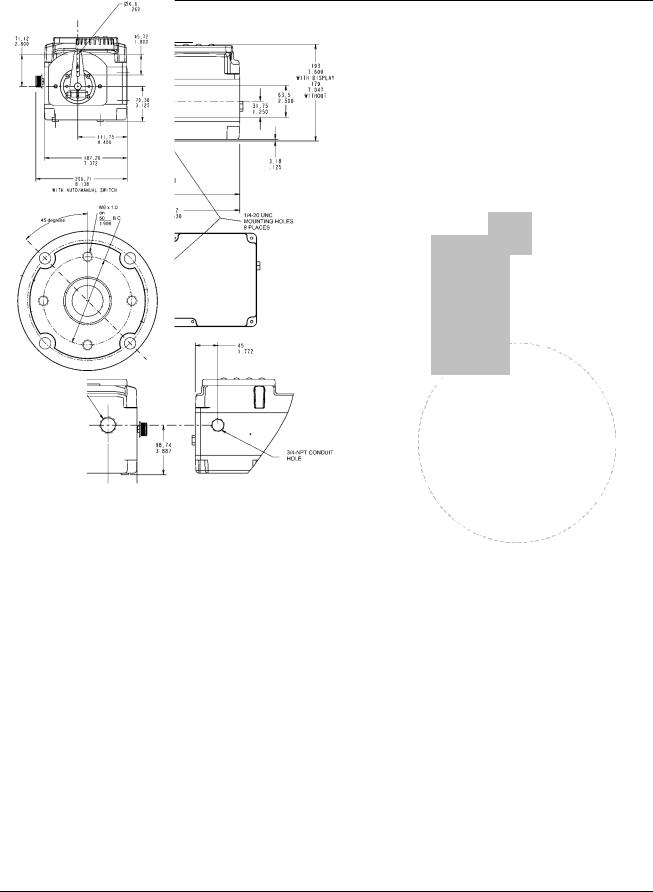
Firmly bolt the actuator to a mounting surface that will not distort when subjected to the torque stresses generated by the actuator. The output shaft of the actuator should be parallel to the output shaft of the driven device. The output shaft crank arm is fully adjustable through 360°.
Mounting holes (bottom and side) and location of shaft/crank arm duplicate mounting for Honeywell Actionators M640A, 740A, 940A for drop-in replacement. Optional adaptor plates available for replacing Landis and Staefa SQM53/56 and Barber Coleman series MP495 models.
Revision 7 |
HercuLine™ 2000 Series Actuator - Installation, Operation and Maintenance Manual |
13 |
7/08 |
|
|
Installation
Actuator Mounting
|
CLEARANCE FOR TOP REMOVAL: |
289 |
101,6 |
11.379 |
4.0 |
|
|
25.4
1.00
mm inches
Figure 3 Outline and Dimensions of HercuLine® 2000 Series Actuators
14 |
HercuLine™ 2000 Series Actuator - Installation, Operation and Maintenance Manual |
Revision 7 |
|
|
7/08 |
Installation
Mechanical Installation
Mechanical Installation
Linkage Set-up
Many applications require the use of a linkage assembly and often the final control element does not have a linear torque curve. The actuator linkage can be set up to achieve an optimal delivered torque distribution for specific applications. To assist with linkage design, Honeywell offers a linkage analysis software application (HAL). The software can be ordered as P/N 51197910-001.
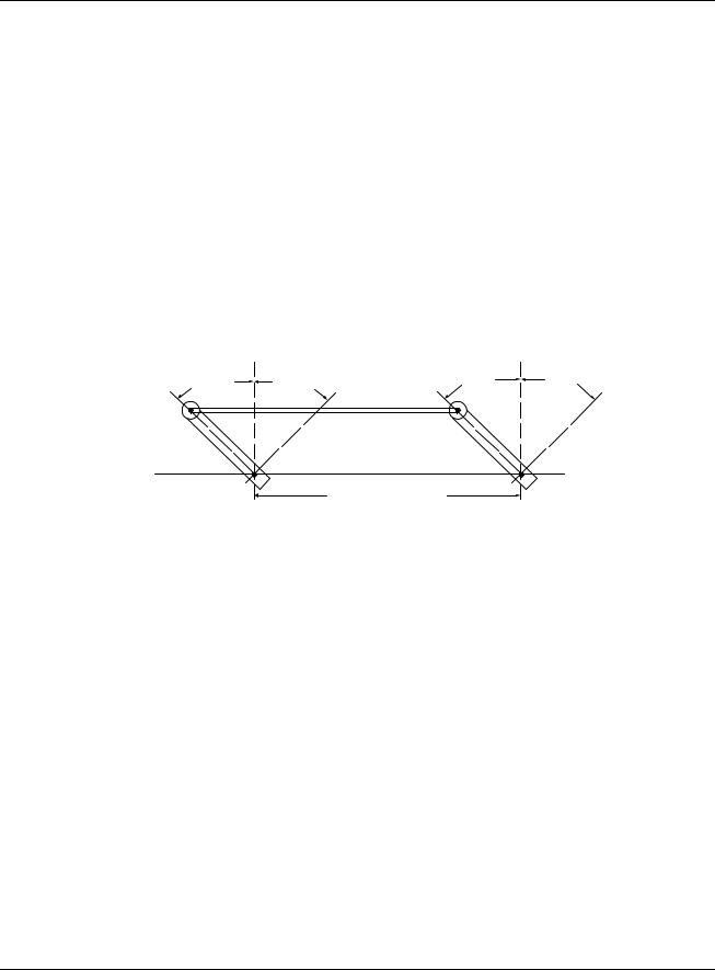
Constant Torque Linkage (typical)
A constant torque linkage is employed when it is desired to provide a linear torque profile throughout the full range of final control element travel. In this situation, the actuator and driven crank arms will be set-up proportionally with respect to each other. Figure 4 shows a general linkage setup to achieve a linear torque profile.
|
Vertical |
|
Vertical |
|
Centerline |
Centerline |
|
45° |
45° |
45° |
45° |
|
|
Linkage |
|
Start |
Stop |
Close |
Open |
Drive Unit |
|
Horizontal Offset |
Damper |
Crank Arm |
|
Crank Arm |
|
|
|
||
|
|
|
a/n 23199 |
|
Figure 4 Constant Torque Linkage |
||
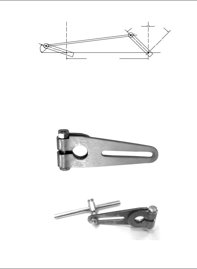
Variable Torque Linkage
A variable torque linkage is employed when it is desired to provide a non-linear torque profile throughout the full range of final control element travel. In this general situation, the actuator and driven crank arms will be set up to provide a higher torque for seating or unseating the final control element. Figure 5 shows a general linkage setup to achieve a non-linear torque profile. Note that this linkage can be characterized in many different ways by varying start angles and rotation requirements of both the Actuator Crank Arm and the Driven Arm.
Revision 7 |
HercuLine™ 2000 Series Actuator - Installation, Operation and Maintenance Manual |
15 |
7/08 |
|
|
Installation
Mechanical Installation
Vertical |
|
Vertical |
|
Centerline |
|
Centerline |
|
|
|
45° |
45° |
Actuator |
Linkage |
|
|
Crank Arm |
|
|
|
|
|
|
|
|
Close |
|
Open |
5° |
Horizontal Offset |
|
Damper |
|
|
||
a/n 23200 |
Crank Arm |
|
Figure 5 Variable Torque Linkage
Actuator Crank Arms
The HercuLine® 2000 Series Actuator comes standard with a crank arm with adjustable radius of 1.0 in (25.4mm) to 2.80 in (71.12mm). See Figure 6.
Figure 6 Standard crank arm
Figure 7 Crank arm with optional ball joint and push rod
16 |
HercuLine™ 2000 Series Actuator - Installation, Operation and Maintenance Manual |
Revision 7 |
|
|
7/08 |

Installation
Electrical Installation
Electrical Installation
General Wiring Recommendations
Only qualified personnel should perform wiring.
Wiring must conform to national and local electrical codes.
In general, copper wire used. Unless locally applicable codes dictate otherwise, the recommended minimum wire sizes in Table 2 should be observed.
|
Table 2 Recommended Minimum Wire Size |
|
|
AWG |
Description |
14 |
Earth ground wire to common power supply. |
18Earth ground wire to single actuator. 120/240 V ac line leads. +24 V and common signal leads. Common signal leads, relays, and aux switches.
Safety Precautions
An external disconnect switch must be installed to break all current carrying conductors connected to the actuator. Turn off power before working on conductors. Failure to observe this precaution may result in serious personal injury.
Actuator Connections
ATTENTION
The ground terminal must be connected to a reliable earth ground.
While the unit is powered, a potentially lethal shock hazard exists inside the case. Do not open the case while the unit is powered. Do not access the terminals while the unit is powered.
The actuator terminal connections for the field wiring are located behind the cover on the actuator case as shown in Figure 2. Power and field wiring is brought into the actuator through two access holes located on the side of the actuator case.
Use both openings: one for low level wiring (control signal) and the other for high level wiring (120Vac).
Do not run both the High Level and Low Level wiring through the same opening.
The screw terminals, locations, and descriptions for all customer connections are identified in the tables and figures that follow.
Revision 7 |
HercuLine™ 2000 Series Actuator - Installation, Operation and Maintenance Manual |
17 |
7/08 |
|
|
Installation
Electrical Installation
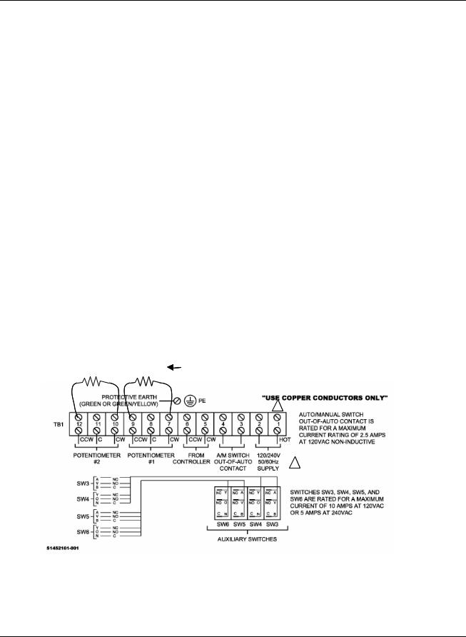
HercuLine® 2000 Terminal Connections
Table 3 Terminal Connections: HercuLine® 2000
Connection |
Terminal Numbers |
Descriptions |
|
and LABEL |
|
|
See Figure 8 |
|
Hot |
1 |
Hot wire for 120/240VAC mains supply. Use only if Auto/Manual |
|
|
switch is present. |
|
|
|
Neutral |
2 |
Neutral wire for 120/240VAC mains supply |
|
|
|
Auto/Manual Switch |
3 |
Switch contact to indicate setting of actuator AUTO/MANUAL |
Contact |
4 |
switch. |
|
|
Switch is closed when actuator is “NOT-IN-AUTO” |
|
|
|
CW from Controller |
5 |
CW motor drive |
|
|
|
CCW from Controller |
6 |
CCW motor drive |
|
|
|
Potentiometer #1 |
7 |
Clockwise-End |
|
8 |
Slider |
|
9 |
Counterclockwise-End |
|
|
|
Potentiometer #2 |
10 |
Clockwise-End |
|
11 |
Slider |
|
12 |
Counterclockwise-End |
|
|
|
Protective Ground |
|
Ground wire connection for mains supply |
|
|
|
158 ohm 158 ohm |
Install resistors to convert 1000 ohm |
|
potentiometer to 135 ohms |
|
1 |
1 REQUIRED ONLY IF AUTO/MANUAL SWITCH IS PRESENT
Figure 8 HercuLine® 2000 connections
18 |
HercuLine™ 2000 Series Actuator - Installation, Operation and Maintenance Manual |
Revision 7 |
|
|
7/08 |
Installation
Electrical Installation
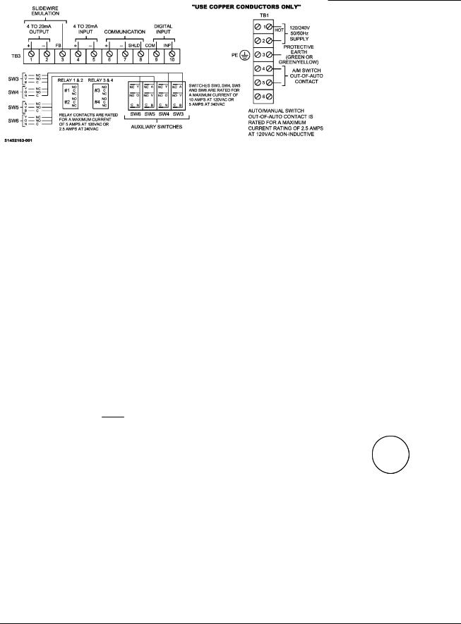
HercuLine® 2001/2002 with Auto/Manual Terminal Connections
Table 4 Terminal Connections: HercuLine® 2001/2002 with auto/manual
Connection |
|
|
Terminal Numbers |
Descriptions |
|
|
|
||||||
|
|
|
|
|
and LABEL |
|
|
|
|
|
|
|
|
|
|
|
|
|
See Figure 9 |
|
|
|
|
|
|
|
|
|
|
|
|
TB1 |
|
|
|
|
|
|
|
||
Hot |
|
1 |
|
|
Hot wire for 120/240VAC mains supply |
|
|
|
|||||
Neutral |
|
2 |
|
|
Neutral wire for 120/240VAC mains supply |
|
|
|
|||||
|
|
|
|
|
|
|
|
|
|
|
|
|
|
Protective Ground |
|
3 |
|
|
Ground wire connection for mains supply |
|
|
|
|||||
|
|
|
|
|
|
|
|
|
|
|
|
||
Auto/Manual Switch |
|
4 |
|
|
Switch contact to indicate setting of actuator AUTO/MANUAL |
||||||||
Contact |
|
5 |
|
|
switch. |
|
|
|
|||||
|
|
|
|
|
|
|
Switch is closed when actuator is “NOT-IN-AUTO” |
|
|
|
|||
|
|
|
6 |
|
|
|
|
|
|
|
|
|
|
|
|
|
|
TB3 |
|
|
|
|
|
|
|
||
4 to 20mA Output* |
|
1 |
(+) |
Analog signal output |
|
|
|
||||||
|
|
|
2 |
(-) |
|
|
|
|
|
|
|
|
|
Feedback |
|
3 |
|
|
Feedback signal used in conjunction with 4 to 20mA OUTPUT |
||||||||
|
|
|
|
|
|
|
voltage when using Slidewire Emulation |
|
|
|
|||
4 to 20mA Input |
|
4 |
(+) |
Analog signal input |
|
|
|
||||||
|
|
|
5 |
(-) |
|
|
|
|
|
|
|
|
|
Modbus |
|
6 |
(+) |
Connection for RS485 Modbus loop wires |
|
|
|
||||||
Communication |
|
7 |
(-) |
|
|
|
|
|
|
|
|
||
|
|
|
8 |
Shield |
|
|
|
|
|
|
|
||
HART Communications |
|
4 |
(+) |
HART Communication is 4-20 mA only. |
|
|
|
||||||
|
|
|
5 |
(-) |
|
|
|
|
|
|
|
|
|
Digital Input |
|
9 |
Com |
Customer’s contact closure |
|
|
|
||||||
|
|
|
|
10 Input |
|
|
|
|
|
|
|
||
|
|
|
|
|
|
|
|
|
|
|
|
|
|
|
|
|
|
HART |
|
|
|
|
|
|
|
||
|
|
Communications |
|
|
|
|
|
|
|
||||
|
|
|
Connection |
|
|
|
|
|
|
|
|||
|
|
+ |
|
_ |
|
|
HART connection using |
||||||
|
|
|
|
|
|||||||||
|
|
|
|
|
|
||||||||
|
|
|
|
|
|
|
|
||||||
|
|
|
|
|
|
|
|
external Turck connector |
|||||
|
|
|
|
|
|
|
|
|
Auxiliary |
||||
|
|
|
|
|
|
|
|
Connector |
|||||
|
|
|
|
|
|
|
|
_ |
|
|
|
+ |
|
|
|
|
|
|
|
|
|
|
|
|
|
||
|
|
|
|
|
|
|
|
|
|
|
|||
|
|
|
|
|
|
|
|
|
|
|
|
|
|
|
|
|
|
|
|
|
|
|
|
|
|
|
|
|
|
|
|
|
|
|
|
Brown |
|
Blue |
|||
|
|
|
|
|
|
|
|
|
|
|
|
|
|
|
|
|
|
|
|
|
|
|
Black |
|
|
|
|
|
|
|
|
|
|
|
|
Black Wire Not Used |
|||||
|
|
|
|
|
|
|
|
|
|
|
|
|
|
Figure 9 HercuLine® 2001/2002 connections
Revision 7 |
HercuLine™ 2000 Series Actuator - Installation, Operation and Maintenance Manual |
19 |
7/08 |
|
|
Installation
Electrical Installation
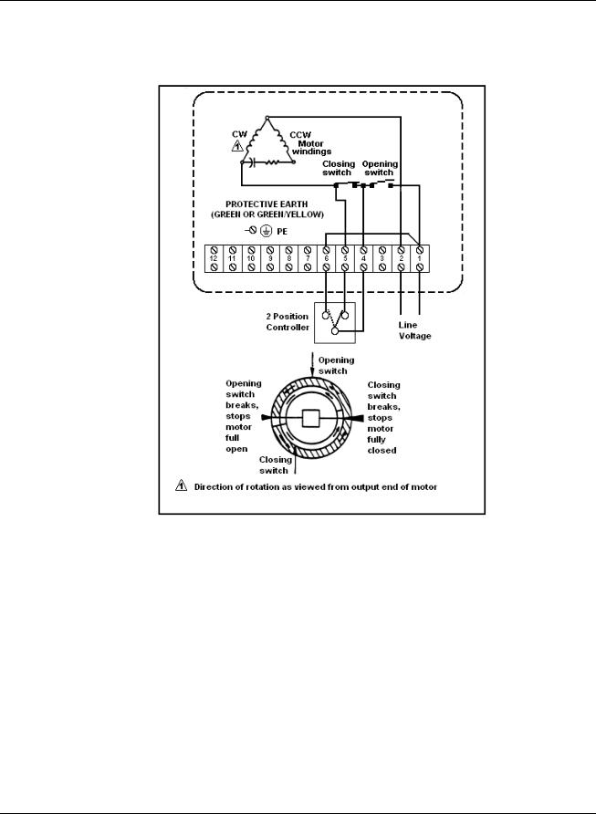
HercuLine® 2003 Wiring Connections and Operation (Actionator 640D Replacement)
Wiring
Figure 10 HercuLine® 2003 connections
Operation
The 2003 actuator is uni-directional (it does not reverse rotation with a reversal in control action). Figure 10 illustrates the internal wiring and the external connections.
The smaller insert of the figure describes the limit switch action for one complete cycle. When the two-position controller detects a sufficient fall in temperature in a heating application, the switch portion between the “4” and “5” terminals will close.
The motor then rotates for 180º or until the opening switch breaks (stops are adjustable, factory set at 180º), and stops in full open position.
A subsequent rise in temperature causes the controller to close the switch between the “4” and “6” terminals when the motor will start to rotate (in the same direction) for 180º or until the closing switch breaks.
The motor stops in the closed position and completes one cycle.
20 |
HercuLine™ 2000 Series Actuator - Installation, Operation and Maintenance Manual |
Revision 7 |
|
|
7/08 |
Installation
Electrical Installation
Power Connections
Depending on which power supply selection is ordered for your actuator, wire the power input (MAINS POWER) as described in the previous tables and figures. Wiring must conform to national and local electrical codes.
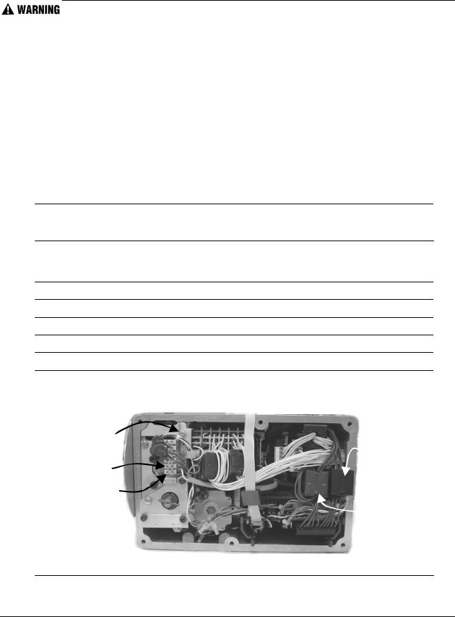
CE Wiring
When wiring the actuator power input for CE approved units, you must also install a MOV and ferrite beads supplied with the CE unit.
You need the following tools:
•5mm hex key
•small flat blade screwdriver
•small needle nose pliers
While the unit is powered, a potentially lethal shock hazard exists inside the case. Do not open the case while the unit is powered. Do not access the terminals while the unit is powered.
Step |
Action |
|
|
|
|
1Remove AC power to actuator.
2Loosen the 6 captive screws (use 5mm hex key) and remove the cover.
3Locate the terminals TB1-1, TB1-2 and ground screw.
4Loosen the screws at terminals TB1-1 and TB1-2. Remove screw used for ground.
5Install the appropriate MOV assembly as shown in Figure 11.
6All ferrites require 1 loop of wire per ferrite. Connect as shown in following steps.
7• Current input and output (slidewire emulation) connection
• Communications and digital input connection
Ground |
|
|
screw |
Current input |
|
|
and output |
|
TB1-2 |
(slidewire |
|
emulation) |
||
|
||
TB1-1 |
|
|
|
Communications |
|
|
and digital input |
Figure 11 CE wiring part 1
Revision 7 |
HercuLine™ 2000 Series Actuator - Installation, Operation and Maintenance Manual |
21 |
7/08 |
|
|

Installation
Electrical Installation
Step |
Action |
|
|
|
|
8• AC power connection
•Auxiliary switches connection
•Relay contact connection
Aux switches 1 and 2
(SW3 and SW4)
 Aux switches 3 and 4
(SW5 and SW6)
 Relays 1 and 2
Relays 3 and 4
AC power connection
Figure 12 CE Wiring part 2
9 Install new gasket and top cover. Secure top cover with 6 captive screws.
10Reapply AC power to the actuator.
11Actuator is ready for use.
Input Signal Connections
ATTENTION
Shielded and grounded cables are recommended.
0/4-20 mA Input Signals
For current signal input, ensure jumper W2 on the CPU PWA is in the “Current” position. See Figure 27 on page 68. Observing polarity, connect the signal input wires TB3–4(+) and TB3–5(-) on CPU terminal board.
0/1-5 Vdc and 0 to 10 Vdc Input Signals
For voltage signal input, ensure jumper W2 on the CPU PWA is in the “Voltage” position. See Figure 27 on page 68. Observing polarity, connect the signal input wires to terminals TB3–4(+) and TB3–5(-) of the terminal block.
22 |
HercuLine™ 2000 Series Actuator - Installation, Operation and Maintenance Manual |
Revision 7 |
|
|
7/08 |
 Loading...