

Page 1

QUADRA-CHEK 2000 Demo
User's Manual
Evaluation Unit
English (en)
06/2018
Page 2

Contents
Contents
1 Fundamentals....................................................................................................................................7
2 Software Installation......................................................................................................................11
3 Basic Operation.............................................................................................................................. 17
4 Software Configuration..................................................................................................................41
5 Quick Start...................................................................................................................................... 47
6 Measurement Report Template.................................................................................................... 69
7 ScreenshotClient.............................................................................................................................83
8 Index.................................................................................................................................................89
9 List of Figures.................................................................................................................................91
2
HEIDENHAIN | QUADRA-CHEK 2000 Demo | User's Manual | 06/2018
Page 3

Contents
1 Fundamentals....................................................................................................................................7
1.1 Overview................................................................................................................................................. 8
1.2 Information on the product.................................................................................................................. 8
1.2.1 Demo software for demonstration of the device functions...................................................... 8
1.2.2 Demo software features............................................................................................................8
1.3 Intended use...........................................................................................................................................9
1.4 Improper use.......................................................................................................................................... 9
1.5 Demo software for demonstration of the device functions.............................................................. 9
1.6 Notes on reading the documentation................................................................................................. 9
1.7 Symbols and fonts used for marking text........................................................................................ 10
2 Software Installation......................................................................................................................11
2.1 Overview............................................................................................................................................... 12
2.2 Downloading the installation file.......................................................................................................12
2.3 System requirements...........................................................................................................................12
2.4 Installing QUADRA-CHEK 2000 Demo under Microsoft Windows.................................................. 13
2.5 Uninstalling QUADRA-CHEK 2000 Demo.......................................................................................... 15
HEIDENHAIN | QUADRA-CHEK 2000 Demo | User's Manual | 06/2018
3
Page 4

Contents
3 Basic Operation.............................................................................................................................. 17
3.1 Overview............................................................................................................................................... 18
3.2 Using the touchscreen and input devices.........................................................................................18
3.2.1 Touchscreen and input devices............................................................................................... 18
3.2.2 Gestures and mouse actions...................................................................................................19
3.3 General operating elements and functions.......................................................................................21
3.4 QUADRA-CHEK 2000 Demo – startup and shut-down.....................................................................23
3.4.1 Starting QUADRA-CHEK 2000 Demo......................................................................................23
3.4.2 Shutting down QUADRA-CHEK 2000 Demo...........................................................................24
3.5 User login and logout......................................................................................................................... 24
3.5.1 User login.................................................................................................................................24
3.5.2 User logout.............................................................................................................................. 24
3.6 Setting the language...........................................................................................................................25
3.7 User interface....................................................................................................................................... 25
3.7.1 User interface after Startup.....................................................................................................25
3.7.2 Main menu of the user interface............................................................................................ 26
3.7.3 Measure menu.........................................................................................................................28
3.7.4 Measurement report menu..................................................................................................... 31
3.7.5 File management menu...........................................................................................................32
3.7.6 User login menu...................................................................................................................... 33
3.7.7 Settings menu..........................................................................................................................34
3.7.8 Switch-off menu.......................................................................................................................35
3.8 Position display.................................................................................................................................... 35
3.8.1 Operating elements of the position display............................................................................ 35
3.9 Working in the workspace.................................................................................................................. 36
3.9.1 Operating elements in the workspace....................................................................................36
3.10 Using the Inspector............................................................................................................................. 37
3.10.1 Operating elements of the Inspector......................................................................................37
3.11 Using measuring tools........................................................................................................................ 40
3.11.1 Measuring tools....................................................................................................................... 40
4
HEIDENHAIN | QUADRA-CHEK 2000 Demo | User's Manual | 06/2018
Page 5

Contents
4 Software Configuration..................................................................................................................41
4.1 Overview............................................................................................................................................... 42
4.2 Activating a license key.......................................................................................................................43
4.3 Copying the configuration file............................................................................................................44
4.4 Uploading the configuration file........................................................................................................ 45
4.5 Setting the language...........................................................................................................................46
4.6 Selecting the product version (optional)...........................................................................................46
5 Quick Start...................................................................................................................................... 47
5.1 Overview............................................................................................................................................... 48
5.2 Conducting a measurement............................................................................................................... 49
5.2.1 Measuring with an OED sensor..............................................................................................49
5.2.2 Displaying and editing the measurement results.................................................................... 57
5.2.3 Creating a measurement report.............................................................................................. 64
6 Measurement Report Template.................................................................................................... 69
6.1 Overview............................................................................................................................................... 70
6.2 Creating and editing a template........................................................................................................ 71
6.2.1 Opening a new template with the editor................................................................................72
6.2.2 Editing the default settings for the measurement report........................................................73
6.2.3 Configuring the page header................................................................................................... 74
6.2.4 Configuring the report header................................................................................................. 76
6.2.5 Defining data for a measurement report.................................................................................78
6.2.6 Saving a template....................................................................................................................81
6.2.7 Exiting or canceling the creation of a template.......................................................................81
6.3 Transferring a measurement report template to the unit................................................................ 81
HEIDENHAIN | QUADRA-CHEK 2000 Demo | User's Manual | 06/2018
5
Page 6

Contents
7 ScreenshotClient.............................................................................................................................83
7.1 Overview............................................................................................................................................... 84
7.2 Informationen about ScreenshotClient..............................................................................................84
7.3 Starting ScreenshotClient...................................................................................................................85
7.4 Connecting ScreenshotClient with the demo software...................................................................85
7.5 Connecting ScreenshotClient with the unit......................................................................................86
7.6 Configuring ScreenshotClient for taking screenshots..................................................................... 86
7.6.1 Configuring the storage location and file name for screenshots.............................................86
7.6.2 Configuring the user interface language of screenshots.........................................................87
7.7 Creating screenshots........................................................................................................................... 88
7.8 Exiting ScreenshotClient.....................................................................................................................88
8 Index.................................................................................................................................................89
9 List of Figures.................................................................................................................................91
6
HEIDENHAIN | QUADRA-CHEK 2000 Demo | User's Manual | 06/2018
Page 7

1
Fundamentals
Page 8

1
Fundamentals | Overview
1.1 Overview
This chapter contains information about the product and these instructions.
1.2 Information on the product
1.2.1 Demo software for demonstration of the device functions
QUADRA-CHEK 2000 Demo is a software application you can install on a
computer independently of the device. QUADRA-CHEK 2000 Demo helps you to
become familiar with, try out or present the functions of the device.
1.2.2 Demo software features
Because of the missing hardware environment, the range of features of the demo
software does not correspond to the complete functional range of the device.
With QUADRA-CHEK 2000 Demo you can try out or present the following
features:
"Conducting a measurement"
"Displaying and editing the measurement results"
"Creating a measurement report"
The following features cannot be tried out or presented with
QUADRA-CHEK 2000 Demo:
Connecting measuring devices
Connecting a network drive
Connecting a USB mass storage device
Connecting a printer
8
HEIDENHAIN | QUADRA-CHEK 2000 Demo | User's Manual | 06/2018
Page 9

Fundamentals | Intended use
1.3 Intended use
The products of the QUADRA-CHEK 2000 series are advanced digital evaluation
electronics for the measurement of 2-D features in metrology applications. The
products are used primarily on measuring machines and profile projectors.
QUADRA-CHEK 2000 Demo is a software product for demonstration of the basic
features of the QUADRA-CHEK 2000 series products. QUADRA-CHEK 2000 Demo
may be used only for presentation, training or testing purposes.
1.4 Improper use
QUADRA-CHEK 2000 Demo is not intended for any use other than the intended
use. Any use for other purposes is prohibited, specifically:
For productive purposes in production systems
As part of production systems
1
1.5 Demo software for demonstration of the device functions
QUADRA-CHEK 2000 Demo is a software application you can install on a
computer independently of the device. QUADRA-CHEK 2000 Demo helps you to
become familiar with, try out or present the functions of the device.
1.6 Notes on reading the documentation
Would you like to see any changes made, or have you found any errors?
We are continuously striving to improve our documentation for you. Please help us
by sending your requests to the following e-mail address:
userdoc@heidenhain.de
HEIDENHAIN | QUADRA-CHEK 2000 Demo | User's Manual | 06/2018
9
Page 10

1
Fundamentals | Symbols and fonts used for marking text
1.7 Symbols and fonts used for marking text
In these instructions the following symbols and fonts are used for marking text:
Depiction Meaning
Bold
...
...
...
...
Identifies an action and the result of this action
Example:
Tap OK
The message is closed
Identifies an item of a list
Example:
TTL interface
EnDat interface
...
Identifies menus, displays and buttons
Example:
Tap Shut down
The operating system shuts down
Turn the power switch off
10
HEIDENHAIN | QUADRA-CHEK 2000 Demo | User's Manual | 06/2018
Page 11

2
Software
Installation
Page 12
2
Software Installation | Overview
2.1 Overview
This chapter provides all of the information needed for downloading and properly
installing QUADRA-CHEK 2000 Demo on a computer.
2.2 Downloading the installation file
Before you can install the demo software on a computer, you need to download an
installation file from the HEIDENHAIN Portal.
To download the installation file from the HEIDENHAIN Portal, you
need access rights to the Software portal folder in the directory of the
appropriate product.
If you do not have access rights to the Portal's Software folder, you can
request the access rights from your HEIDENHAIN contact person.
Download the latest version of QUADRA-CHEK 2000 Demo here:
www.heidenhain.de
Select the download folder of your browser
Unpack the downloaded file with the extension .zip into a temporary storage
folder
The following files will be unpacked into the temporary storage folder:
Installation file with the extension .exe
File DemoBackup.mcc
2.3 System requirements
If you want to install QUADRA-CHEK 2000 Demo on a computer, the computer
system must meet the following requirements:
Microsoft Windows 7 or higher
Screen resolution of at least 1280 × 800 recommended
12
HEIDENHAIN | QUADRA-CHEK 2000 Demo | User's Manual | 06/2018
Page 13

Software Installation | Installing QUADRA-CHEK 2000 Demo under Microsoft Windows
2.4 Installing QUADRA-CHEK 2000 Demo under Microsoft Windows
Select the temporary storage folder into which you unpacked the downloaded
file with the .zip extension
Further information: "Downloading the installation file", Page 12
Run the installation file with the extension .exe
The installation wizard is opened:
2
Figure 1: Installation wizard
Tap Next
In the License Agreement installation step, accept the terms of the license
Tap Next
In the Select Destination Location installation step, the
installation wizard suggests a storage location. We recommend
retaining the suggested storage location.
In the Select Destination Location installation step, select the storage
location to which you want to save QUADRA-CHEK 2000 Demo
Tap Next
In the Select Components installation step, the ScreenshotClient
program is also installed by default. ScreenshotClient enables you
to take screenshots of the active screen.
If you want to install ScreenshotClient
In the Select Components installation step, leave the default
settings unchanged
Further information: "ScreenshotClient", Page 83
In the Select Components installation step:
HEIDENHAIN | QUADRA-CHEK 2000 Demo | User's Manual | 06/2018
13
Page 14

2
Software Installation | Installing QUADRA-CHEK 2000 Demo under Microsoft Windows
Select the type of installation
Activate or deactivate the option Screenshot Utility
Figure 2: Installation wizard with activated demo software option and Screenshot
Utility
Tap Next
In the Select Start Menu Folder installation step, select the storage location at
which you want to create the start menu folder
Tap Next
In the Select Additional Tasks installation step, select or deselect Desktop
icon
Tap Next
Tap Install
Installation starts—the status of installation is shown in the progress bar
After installation has been completed successfully, use Finish to close the
installation wizard
The program has been successfully installed on your computer
14
HEIDENHAIN | QUADRA-CHEK 2000 Demo | User's Manual | 06/2018
Page 15

Software Installation | Uninstalling QUADRA-CHEK 2000 Demo
2.5 Uninstalling QUADRA-CHEK 2000 Demo
Select in succession in Microsoft Windows:
Start
All programs
HEIDENHAIN
QUADRA-CHEK 2000 Demo
Tap Uninstall
The uninstallation wizard opens
To confirm unistallation, tap Ja
Unistallation starts, and the progress bar indicates the status of the unistallation
process
After uninstallation has been completed successfully, close the uninstallation
wizard with OK
The program has been successfully removed from your computer
2
HEIDENHAIN | QUADRA-CHEK 2000 Demo | User's Manual | 06/2018
15
Page 16

Page 17

3
Basic Operation
Page 18

3
Basic Operation | Overview
3.1 Overview
This chapter describes the user interface, operating elements, and basic functions
of QUADRA-CHEK 2000 Demo.
3.2 Using the touchscreen and input devices
3.2.1 Touchscreen and input devices
The operating elements on the user interface from QUADRA-CHEK 2000 Demo
are operated via a touchscreen or a connected mouse.
To enter data, you can use the screen keyboard of the touchscreen or a connected
keyboard keyboard.
18
HEIDENHAIN | QUADRA-CHEK 2000 Demo | User's Manual | 06/2018
Page 19

Basic Operation | Using the touchscreen and input devices
3.2.2 Gestures and mouse actions
To activate, switch or move the operating elements of the user interface, you can
use QUADRA-CHEK 2000 Demo's touchscreen or a mouse. Gestures are used to
operate the touchscreen and the mouse.
The gestures for operating the touchscreen may differ from the
gestures for operating the mouse.
If the gestures for operating the touchscreen differ from those for
operating the mouse, then these instructions describe both operating
options as alternative actions.
The alternative actions for operating the touchscreen or the mouse are
identified by the following symbols:
Operation using the touchscreen
Operation using the mouse
3
The following overview describes the different gestures for operating the
touchscreen or the mouse:
Tapping
Means touching the screen briefly with your fingertip
Means pressing the left mouse button once
The actions initiated by tapping include
Selection of menus, features or parameters
Entering characters with the screen keyboard
Closing dialogs
Displaying and hiding the main menu in the Measure menu
Displaying and hiding the Inspector in the Measure menu
Holding
Means touching the screen and holding your finger(s) on it for a
few seconds
Means pressing the left mouse button once and holding it
down
The actions initiated by holding are
Quickly changing the values in input fields with plus and
minus buttons
HEIDENHAIN | QUADRA-CHEK 2000 Demo | User's Manual | 06/2018
19
Page 20

3
Basic Operation | Using the touchscreen and input devices
Dragging
Is a combination of long press and then swipe, moving a finger
over the touchscreen when at least the starting point of motion
is defined
Means pressing the left mouse button once and holding it
down while moving the mouse; at least the starting point of the
motion is defined
The actions initiated by dragging include
Scrolling through lists and texts
Opening the Details dialog in the Inspector
Two-finger drag
Refers to the movement of two fingers across the touchscreen
when at least the starting point of the movement is clearly
defined
Refers to pressing the right mouse button once and holding it
down while moving the mouse; at least the starting point of the
movement is defined
Two-finger dragging initiates the following action
In the Measure menu, moving the features view within the
workspace
20
HEIDENHAIN | QUADRA-CHEK 2000 Demo | User's Manual | 06/2018
Page 21

Basic Operation | General operating elements and functions
3.3 General operating elements and functions
The operating elements described below are available for configuration and
operating the product via the touchscreen or input devices.
Screen keyboard
With the screen keyboard, you can enter text into the input fields of the user
interface. The displayed screen keyboard is either numeric or alphanumeric,
depending on the input field.
To enter values, tap an input field
The input field is highlighted
The screen keyboard is displayed
Enter text or numbers
In some input fields, a green check mark indicates that the entry is correct
If the entry is incomplete or incorrect, a red exclamation mark is displayed. The
entry cannot be concluded in this case
To apply the values, confirm the entry with RET
The values are displayed
The screen keyboard disappears
3
Input fields with plus and minus buttons
To adjust a numerical value, use the + (plus) and – (minus) buttons to the left and
right of the numerical value.
Tap + or – until the desired value is displayed
Long-press + or – to scroll through the values more
quickly
The selected value is displayed
Toggle switch
Use the toggle switch to switch between functions.
Tap the desired function
The active function is shown in green
The inactive function is shown in light gray
Slide switch
With the sliding switch, you can activate or deactivate a function.
Drag the sliding switch to the desired position or tap the
sliding switch
The function is activated or deactivated
Slider
With the slider, you can continuously adjust values.
Drag the slider to the desired position
The selected value is displayed graphically or in percent
HEIDENHAIN | QUADRA-CHEK 2000 Demo | User's Manual | 06/2018
21
Page 22
3
Basic Operation | General operating elements and functions
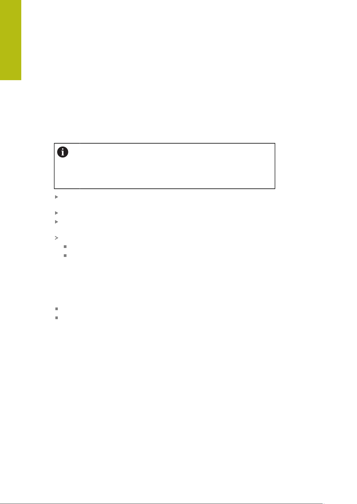
Drop-down list
Buttons that open drop-down lists are indicated by a triangle pointing down.
Tap the button
The drop-down list opens
The active entry is highlighted in green
Tap the desired entry
The selected entry is applied
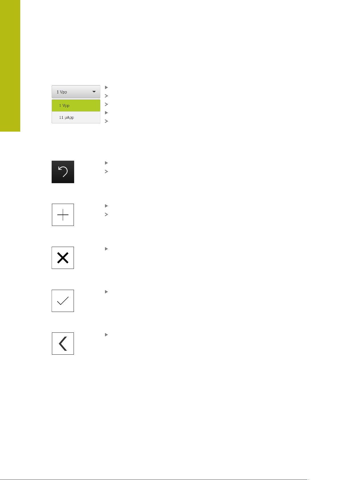
Undo
With this button, you can undo the last action.
Processes that have already been concluded cannot be undone.
Tap Undo
The last action is undone
Add
Close
Confirm
Back
To add a feature, tap Add
The new feature is added
Tap Close to close a dialog
Tap Confirm to conclude an activity
Tap Back to return to the higher level in the menu
structure
22
HEIDENHAIN | QUADRA-CHEK 2000 Demo | User's Manual | 06/2018
Page 23

Basic Operation | QUADRA-CHEK 2000 Demo – startup and shut-down
3.4 QUADRA-CHEK 2000 Demo – startup and shut-down
3.4.1 Starting QUADRA-CHEK 2000 Demo
Before using QUADRA-CHEK 2000 Demo, you need to perform the
steps for configuring the software.
Tap QUADRA-CHEK 2000 Demo on the Microsoft Windows
desktop
or
Select in succession in Microsoft Windows:
Start
All programs
HEIDENHAIN
QUADRA-CHEK 2000 Demo
3
Two executable files with different modes of
appearance are available:
QUADRA-CHEK 2000 Demostarts within a
Microsoft Windows window
QUADRA-CHEK 2000 Demo (full screen):
starts in full-screen mode
Tap QUADRA-CHEK 2000 Demo or
QUADRA-CHEK 2000 Demo (full screen)
QUADRA-CHEK 2000 Demo starts an output window in the
background. The output window is not relevant for operation
and is closed again when QUADRA-CHEK 2000 Demo is shut
down
QUADRA-CHEK 2000 Demo starts the user interface with
the User login menu
Figure 3: User login menu
HEIDENHAIN | QUADRA-CHEK 2000 Demo | User's Manual | 06/2018
23
Page 24

3
Basic Operation | QUADRA-CHEK 2000 Demo – startup and shut-down
3.4.2 Shutting down QUADRA-CHEK 2000 Demo
Tap Switch off in the main menu
Tap Shut down
QUADRA-CHEK 2000 Demo is shut down
To shut down QUADRA-CHEK 2000 Demo in the Microsoft Windows
window, also use the Switch-off menu.
If you use Close to close the Microsoft Windows window, all settings
will be lost.
3.5 User login and logout
In the User login menu, you can log in and out of the product as a user.
Only one user can be logged in to the product at a time. The logged-in user is
displayed. Before a new user can log in, the logged-in user has to log out.
The product provides various authorization levels that grant the user full
or restricted access to management and operation functionality.
3.5.1 User login
Tap User login in the main menu
In the drop-down list, select the OEM user
Tap the Password input field
Enter the password "oem" of the OEM user
Confirm entry with RET
Tap Log in
The user is logged in and the Measure menu is displayed
3.5.2 User logout
24
Tap User login in the main menu
Tap Log out
The user is logged out
All functions of the main menu are inactive, except for Switch
off
The product can only be used again after a user has logged in
HEIDENHAIN | QUADRA-CHEK 2000 Demo | User's Manual | 06/2018
Page 25

Basic Operation | Setting the language
3.6 Setting the language
The default language for the user interface is English. You can switch the user
interface to the desired language.
Tap Settings in the main menu
Tap User
The logged-in user is indicated by a check mark
Select the logged-in user
The language selected for the user is indicated by a national
flag in the Language drop-down list
Select the flag for the desired language in the Language
drop-down list
The user interface is displayed in the selected language
3
3.7 User interface
3.7.1 User interface after Startup
User interface after startup
If automatic user login is active and the last user who logged in was of the
Operator type, the Measure menu with the workspace and the Inspector is
displayed after the product has started up.
If automatic user login is not active, the product opens the User login menu.
Further information: "User login menu", Page 33
HEIDENHAIN | QUADRA-CHEK 2000 Demo | User's Manual | 06/2018
25
Page 26

3
1
2
0
Basic Operation | User interface
3.7.2 Main menu of the user interface
User interface with QUADRA-CHEK 2000 OED software option
Figure 4: User interface with QUADRA-CHEK 2000 OED software option
1
Message display area, which displays the time and the number of unclosed
messages
2
Main menu with operating elements
Operating elements of the main menu
The main menu is displayed regardless of the activated software options.
Operating
element
Function
Message
Display of an overview of all messages as well as the
number of messages that have not been closed
Measure
Manual measurement, construction, and definition of
features by means of measuring programs and predefined
geometries
Further information: "Measure menu", Page 28
Measurement report
Creation of measurement reports based on templates
Further information: "Measurement report menu",
Page 31
File management
26
Management of the files that are available on the product
Further information: "File management menu",
Page 32
User login
Login and logout of the user
Further information: "User login menu", Page 33
HEIDENHAIN | QUADRA-CHEK 2000 Demo | User's Manual | 06/2018
Page 27

Basic Operation | User interface
3
Operating
element
Function
Settings
Settings of the unit, such as setting up users, configuring
sensors, and updating the firmware
Further information: "Settings menu ", Page 34
Switch-off
Shutdown of the operating system or activation of energysaving mode
Further information: "Switch-off menu", Page 35
HEIDENHAIN | QUADRA-CHEK 2000 Demo | User's Manual | 06/2018
27
Page 28

3
1
2
3
4
6 5
Basic Operation | User interface
3.7.3 Measure menu
Activation
Tap Measure in the main menu
The user interface for manual measuring, constructing and
defining is displayed
Measure menu with QUADRA-CHEK 2000 OED software option
Figure 5: Measure menu with QUADRA-CHEK 2000 OED software option
1
The function palette provides functions for manual measuring and defining. The
selected function is displayed as an active operating element.
2
The sensor palette contains the optional sensors (e.g., OED). It is only visible if
the software option is active.
3
The workspace displays, for example, the position display or the input area for
constructing and defining features.
4
The Inspector contains the quick access menu, the position preview, the
features preview, and the feature list or the program step list. The feature list
contains the features that have been measured, constructed, or defined.
5
The geometry palette provides all of the geometries for manual measuring,
constructing, and defining. The geometries are partially combined into
geometry groups. The selected geometry is displayed as an active feature. The
geometries available on the geometry palette depend on the selected function.
6
The tool palette provides the measuring tools required for conducting the
selected measurement.
28
HEIDENHAIN | QUADRA-CHEK 2000 Demo | User's Manual | 06/2018
Page 29

Basic Operation | User interface
Measure
Define
Operating elements of the function palette
3
Manual
Defining
measuring
Operating elements of the sensor palette
The operating elements of the sensor palette are only available if software options
are active. If one software option is active, the software option is displayed. If
multiple software options are active, you can choose between the options.
Optical edge
detection
(OED)
HEIDENHAIN | QUADRA-CHEK 2000 Demo | User's Manual | 06/2018
29
Page 30

3
Point
Circle
Arc
Ellipse
Slot
Rectangle
Distance
Angle
Zero point
Alignment
Ref. plane
Crosshair
OED
Auto OED
Basic Operation | User interface
Operating elements of the geometry palette
Measure Magic
Point
Line
Circle Arc Ellipse
Slot Rectangle
Distance Angle
Blob
Zero point Alignment Reference
plane
The Reference plane operating element is only available if
the Z axis is active.
30
Operating elements of the OED tool palette
The operating elements of the tool palette are only available if a software option
is active. They are only displayed in the manual measuring function if optical edge
detection is activated.
Crosshair OED Auto OED
HEIDENHAIN | QUADRA-CHEK 2000 Demo | User's Manual | 06/2018
Page 31

Basic Operation | User interface
1
2
3
3.7.4 Measurement report menu
Activation
Tap Measurement report in the main menu
The user interface for displaying and creating the
measurement reports appears
Short description
3
Figure 6: Measurement report menu
1
List of default templates
2
Preview of the selected template
3
Display of information on the selected template
In the Measurement report menu, you can select report templates. A list of the
templates is shown in the left-hand column. A preview of the selected template is
displayed in the right-hand column.
HEIDENHAIN | QUADRA-CHEK 2000 Demo | User's Manual | 06/2018
31
Page 32

3
1
2
Basic Operation | User interface
3.7.5 File management menu
Activation
Tap File management in the main menu
The user interface for file management is displayed
Short description
Figure 7: File management menu
1
List of available storage locations
2
List of folders in the selected storage location
The File management menu shows an overview of the files stored in the unit’s
memory.
32
HEIDENHAIN | QUADRA-CHEK 2000 Demo | User's Manual | 06/2018
Page 33

Basic Operation | User interface
1
2
3.7.6 User login menu
Activation
Tap User login in the main menu
The user interface for user login and logout is displayed
Short description
3
Figure 8: User login menu
1
Display of the logged-in user
2
User login
The User login menu shows the logged-in user in the column on the left. The login
of a new user is displayed in the right-hand column.
To log in another user, the logged-in user must first log out.
Further information: "User login and logout", Page 24
HEIDENHAIN | QUADRA-CHEK 2000 Demo | User's Manual | 06/2018
33
Page 34

3
1 2
Basic Operation | User interface
3.7.7 Settings menu
Activation
Tap Settings in the main menu
The user interface for the device settings is displayed
Short description
Figure 9: Settings menu
1
List of setting options
2
List of setting parameters
The Settings menu shows all options for configuring the product. With the setting
parameters, you can adapt the product to on-site requirements.
The product provides various authorization levels that grant the user full
or restricted access to management and operation functionality.
34
HEIDENHAIN | QUADRA-CHEK 2000 Demo | User's Manual | 06/2018
Page 35

Basic Operation | User interface
X
R
R
3.7.8 Switch-off menu
Activation
Tap Switch off in the main menu
The operating elements for shutting down the operating
system, for activating the energy-saving mode and for
activating the cleaning mode are displayed
Short description
The Switch off menu provides the following options:
3
Operating
element
Further information: "QUADRA-CHEK 2000 Demo – startup and shut-down",
Page 23
Function
Shut down
Shuts down QUADRA-CHEK 2000 Demo
Energy saving mode
Switches the screen off and puts the operating system into
energy-saving mode
Cleaning mode
Switches the screen off; the operating system continues
unchanged
3.8 Position display
The unit’s position display shows the axis positions and additional information
about the configured axes (if applicable).
3.8.1 Operating elements of the position display
Symbol Meaning
Axis key
Axis key functions:
Tapping the axis key: Opens the input field for position value
Holding down the axis key: sets the current position as zero
point
Reference mark search performed successfully
Reference mark search not performed or no reference mark
detected
HEIDENHAIN | QUADRA-CHEK 2000 Demo | User's Manual | 06/2018
35
Page 36

3
Basic Operation | Working in the workspace
3.9 Working in the workspace
The workspace is only available in the Measure menu.
Activation
Tap Measure in the main menu
The user interface for manual measuring, constructing and
defining is displayed
3.9.1 Operating elements in the workspace
Operating elements of the manual measuring function for adjusting the
features view in the case of reduced workspace
Display
annotations
Zoom functions
Regardless of the size of the workspace, the available functions are gathered
together in the Zoom functions.
Zoom
functions
Operating elements of the definition function
Depending on the selected geometry, the input fields required for definition are
displayed in the workspace.
Settings
Zoom to all Zoom to
selection
Magnify
graphic
Reduce
graphic
36
Figure 10: Operating elements of the Define function for the Circle geometry
HEIDENHAIN | QUADRA-CHEK 2000 Demo | User's Manual | 06/2018
Page 37

Basic Operation | Using the Inspector
3.10 Using the Inspector
The Inspector is only available in the Measure menu.
Activation
Tap Measure in the main menu
The user interface for measuring, constructing and defining is
displayed
3.10.1 Operating elements of the Inspector
3
Operating
element
Short description
Quick access menu
The quick access menu displays the current settings for
manual measuring, constructing and defining:
Unit of measurement for linear values (millimeters or
inches)
Magnification used
Type of measuring point acquisition (automatic or
manual)
Coordinate system used
To adjust the settings of the quick access menu, tap the
quick access menu
Position preview
The position preview is only available in the manual
measuring function.
The current axis positions are displayed. If no reference
mark search has been performed, the axis positions are
displayed in red.
To display the position preview in the workspace, tap
the Position preview
The position preview is displayed in the workspace
The current content of the workspace switches to the
Inspector
Features preview
The features preview is available only in the measuring
function.
The features preview displays a reduced view of the
measured, constructed and, defined features.
To display the features view in the workspace, tap
Features preview
The features view is displayed in the workspace
The current content of the workspace switches to the
Inspector
HEIDENHAIN | QUADRA-CHEK 2000 Demo | User's Manual | 06/2018
37
Page 38

3
1
2
3
45
Basic Operation | Using the Inspector
Operating
element
Short description
Feature list
The feature list contains a list of all features that have been
measured, constructed, or defined. The feature list provides
the following information:
1: Measured feature with symbol, name, and
consecutive number
2: Function that was used for creating the feature
Symbol Meaning
Measured feature
Constructed feature
Defined feature
3: Concludes the measuring point acquisition
4: Number of measuring points that have been acquired
5: Newly acquired feature with symbol
Each feature contains details on the measurement results
as well as selectable tolerances.
To display the measured values and adjust the
tolerances, drag a feature into the workspace
The detail window with the Overview and Tolerance
tabs opens in the workspace
To select or deselect features, tap the features in
succession
The selected features are highlighted in green
To delete a feature, drag the feature to the right and out
of the Inspector
Measurement result preview
The measurement result preview is displayed in the
workspace after a measurement process is concluded and
shows information about the measured feature. For each
geometry time, it is possible to define which parameters
are shown in the measurement result preview. The respective geometry type determines which parameters are available.
38
HEIDENHAIN | QUADRA-CHEK 2000 Demo | User's Manual | 06/2018
Page 39

Basic Operation | Using the Inspector
3
Operating
element
Short description
Program step list
The program step list shows all actions that occur during
the measurement. It is displayed instead of the feature list
in the Inspector.
The program steps can be combined and saved as measuring programs.
Auxiliary functions
The auxiliary functions contain the following functions:
Switching the display between feature list and program
step list
Creating, saving, and opening a program
Calling the program control in the workspace
Opening and saving a coordinate system
Deleting selected features or all features from the
feature list
Feature selection
Multiple selection of features of the same geometry type
Tap Feature selection
To select all features of a geometry type in the feature
list, tap the desired geometry type
Confirm with OK
The selected features are highlighted in green
Enter
Acquisition of measuring points with the following options:
If measuring point acquisition is deactivated, then the
measuring points will be acquired manually
If automatic measuring point acquisition is active, then
a red dot will be shown in the operating element. The
measuring points will be acquired after expiration of the
set timeout
HEIDENHAIN | QUADRA-CHEK 2000 Demo | User's Manual | 06/2018
39
Page 40

3
Crosshair
OED
Auto OED
Basic Operation | Using measuring tools
3.11 Using measuring tools
The operating elements of the tool palette are only available if an optical
sensor is active. They are shown in the manual measuring function with
the following views of the workspace:
With OED optical sensor, if the position display or the features view is
in the workspace
3.11.1 Measuring tools
Depending on the optical sensor, various measuring tools are available for
acquiring the measuring points. The measuring tools can be operated by gestures
in the workspace.
OED measuring tools
Symbol Measuring tool Functions and characteristics
Crosshair Manual acquisition of single measuring points
No automatic acquisition of light-to-dark transitions
OED Active measuring tool
Acquisition of light-to-dark transitions
Buffering of a single measuring point (manual
confirmation required)
If the OED sensor traverses an edge, a measuring
point is buffered in the clipboard. If the OED sensor
traverses a further edge, the buffered measuring
point is overwritten. By tapping Enter, the previously
buffered measuring point is added to the feature calculation.
Auto OED Active measuring tool
Automatic acquisition of measuring points, e.g. on
circles and circular arcs
Acquisition of light-to-dark transitions
If the OED sensor traverses an edge, a measuring
point is automatically acquired and added to the
feature calculation.
40
HEIDENHAIN | QUADRA-CHEK 2000 Demo | User's Manual | 06/2018
Page 41

4
Software
Configuration
Page 42

4
Software Configuration | Overview
4.1 Overview
Make sure that you have read and understood the "Basic Operation"
chapter before carrying out the actions described below.
Further information: "Basic Operation", Page 17
Before you can use QUADRA-CHEK 2000 Demo correctly after successful
installation, you need to configure QUADRA-CHEK 2000 Demo. This chapter
describes how to perform the following settings:
Activating a license key
Copying the configuration file
Uploading the configuration file
Setting the language
Selecting the product version (optional)
42
HEIDENHAIN | QUADRA-CHEK 2000 Demo | User's Manual | 06/2018
Page 43

Software Configuration | Activating a license key
4.2 Activating a license key
With QUADRA-CHEK 2000 Demo, you can also simulate functions that are
dependent on a software option. To do so, you must enable the software option
with a license key. The required license key is stored in a license file in the folder
structure of QUADRA-CHEK 2000 Demo.
You must upload the license file in order to enable the available software options.
Tap Settings in the main menu
The unit’s settings appear
4
Figure 11: Settings menu
Tap Service
Open in the sequence
Software options
Activate options
Tap Read license file
Select the storage location in the dialog:
Select Internal
Select User
Select the PcDemoLicense.xml license file
Confirm your selection with OK
Tap OK
The license key is activated
Tap OK
You are prompted to restart
Use Cancel to deny restarting
The functions dependent on the software options are
available
HEIDENHAIN | QUADRA-CHEK 2000 Demo | User's Manual | 06/2018
43
Page 44

4
Software Configuration | Copying the configuration file
4.3 Copying the configuration file
Before you can load the configuration data in QUADRA-CHEK 2000 Demo, you
must first copy the downloaded configuration file DemoBackup.mcc to an area
that can be accessed by QUADRA-CHEK 2000 Demo.
Move to the temporary storage folder
For example, copy the configuration file DemoBackup.mcc to the following
folders:C: HEIDENHAIN [product name] Metrology ProductsMGE5
[product designation] user User
In order for QUADRA-CHEK 2000 Demo to access the
configuration file DemoBackup.mcc, you must retain the following
part of the path when you save the file: [product name]
ProductsMGE5 Metrology [product abbreviation] user
User.
The configuration file can be accessed by QUADRA-CHEK 2000 Demo
44
HEIDENHAIN | QUADRA-CHEK 2000 Demo | User's Manual | 06/2018
Page 45

Software Configuration | Uploading the configuration file
4.4 Uploading the configuration file
Before you can upload the configuration data, you must first activate
the license key.
Further information: "Activating a license key", Page 43
In order to configure QUADRA-CHEK 2000 Demo for the application on the
computer, you must upload the configuration file DemoBackup.mcc.
Tap Settings in the main menu
The product settings are displayed
4
Figure 12: Settings menu
Tap Service
Open in the sequence
Back up and restore
Restore settings
Complete restoration
Select the storage location in the dialog:
Internal
User
Select the DemoBackup.mcc configuration file
Confirm your selection with OK
The settings are applied
You are prompted to shut down the application
Tap OK
QUADRA-CHEK 2000 Demo is shut down, and the Microsoft
Windows window is closed
Restart QUADRA-CHEK 2000 Demo
QUADRA-CHEK 2000 Demo is ready for use
HEIDENHAIN | QUADRA-CHEK 2000 Demo | User's Manual | 06/2018
45
Page 46

4
Software Configuration | Setting the language
4.5 Setting the language
The default language for the user interface is English. You can switch the user
interface to the desired language.
Tap Settings in the main menu
Tap User
The logged-in user is indicated by a check mark
Select the logged-in user
The language selected for the user is indicated by a national
flag in the Language drop-down list
Select the flag for the desired language in the Language
drop-down list
The user interface is displayed in the selected language
4.6 Selecting the product version (optional)
QUADRA-CHEK 2000 is available in different versions. These versions differ in their
interfaces for connectible encoders:
QUADRA-CHEK 2013 version for encoders with 1 VPP interface
QUADRA-CHEK 2023 version for encoders with TTL interface
The QUADRA-CHEK 2093 version for encoders with various interfaces (1 V
and TTL)
In the Settings menu, you can select the version that is to be simulated with
QUADRA-CHEK 2000 Demo
Tap Settings in the main menu
Tap Service
Tap Product designation
Select the desired version
You are now prompted to perform a restart
QUADRA-CHEK 2000 Demo is ready for use in the desired
version
PP
46
HEIDENHAIN | QUADRA-CHEK 2000 Demo | User's Manual | 06/2018
Page 47

5
Quick Start
Page 48

5
Quick Start | Overview
5.1 Overview
In this chapter an example is used to describe the steps of a typical measuring
sequence. The steps range e.g. from aligning the measured object and measuring
the features through to creating the measurement report.
For a detailed description of the individual activities, please refer to the
"Measuring," "Measurement evaluation" and "Measurement reports"
chapters in the QUADRA-CHEK 2000 operating instructions.
Make sure that you have read and understood the "Basic Operation"
chapter before carrying out the actions described below.
Further information: "Basic Operation", Page 17
48
HEIDENHAIN | QUADRA-CHEK 2000 Demo | User's Manual | 06/2018
Page 49

Quick Start | Conducting a measurement
5.2 Conducting a measurement
5.2.1 Measuring with an OED sensor
The measurements shown here cannot be simulated with QUADRACHEK 2000 Demo, because the corresponding measuring point
acquisition is not possible without a measuring device and OED sensor.
However, you can use the descriptions to familiarize yourself with the
most important functions and the user interface.
For the measurement of edges and contours with an OED sensor, various
measuring tools are available to you for the acquisition of measuring points.
Further information: "Measuring tools", Page 40
Aligning the measured object
Before you can evaluate the measuring points, you need to align the measured
object. During this process, the coordinate system of the measured object
(workpiece coordinate system) is determined, which is specified in the technical
drawing.
This makes it possible to compare the measured values with the data in the
technical drawing and assess them.
5
Figure 13: Example of aligning a 2-D demo part
Measured objects are usually aligned in the following steps:
1 Measuring the alignment
2 Measuring a straight line
3 Constructing the zero point
HEIDENHAIN | QUADRA-CHEK 2000 Demo | User's Manual | 06/2018
49
Page 50

5
Quick Start | Conducting a measurement
Measuring the alignment
Define the reference edge for the alignment according to the technical drawing.
Tap Measure in the main menu
Select Manual measuring in the function palette
If multiple sensors are activated, then select OED sensor in
the sensor palette
The geometry palette and the OED measuring tools are now
displayed
The workspace now shows the position display
In the quick access menu, select the magnification that is set
on the measuring machine
Select Alignment in the geometry palette
Select Auto OED in the tool palette
Cross over the reference edge multiple times with the OED
sensor
A new feature is displayed in the feature list of the Inspector
A new measuring point is added for each pass over the
reference edge
Distribute the measuring points along the entire
length of the edge, as far as possible. This
minimizes the angular error.
Tap Finish in the new feature
The alignment is displayed in the feature list of the Inspector
The measurement result preview is now displayed
50
Figure 14: Alignment feature in the feature list with Measurement result preview
HEIDENHAIN | QUADRA-CHEK 2000 Demo | User's Manual | 06/2018
Page 51

Quick Start | Conducting a measurement
Measuring a straight line
A straight line is measured as the second reference edge.
Select Line in the geometry palette
Select Auto OED in the tool palette
Cross over the reference edge multiple times with the OED
sensor
A new feature is displayed in the feature list of the Inspector
A new measuring point is added for each pass over the
reference edge
Distribute the measuring points along the entire
length of the edge, as far as possible. This
minimizes the angular error.
5
Tap Finish in the new feature
The line is displayed in the feature list of the Inspector
The measurement result preview is now displayed
Figure 15: Line feature in the feature list with Measurement result preview
HEIDENHAIN | QUADRA-CHEK 2000 Demo | User's Manual | 06/2018
51
Page 52

5
Quick Start | Conducting a measurement
Constructing the zero point
The zero point is constructed from the point of intersection between the alignment
and the straight line.
Select Zero point in the geometry palette
Select the Alignment and Line features in the Inspector or in
the features view
The selected features are displayed in green
A new feature with the selected geometry is displayed
Tap Finish in the new feature
The zero point is created
The workpiece coordinate system for the measured object
has been determined
Tap Features preview
The coordinate system is shown in the workspace
52
Figure 16: Workspace with zero point displayed in the coordinate system
HEIDENHAIN | QUADRA-CHEK 2000 Demo | User's Manual | 06/2018
Page 53

Quick Start | Conducting a measurement
Measuring features
To measure features, you can use the geometries of the geometry palette.
5
Figure 17: Examples of measuring a 2-D demo part
The section below describes measuring the following features:
1 Circle
2 Slot
3 Blob
HEIDENHAIN | QUADRA-CHEK 2000 Demo | User's Manual | 06/2018
53
Page 54

5
Quick Start | Conducting a measurement
Measuring a circle
A minimum of three measuring points is required to measure a circle. For
measuring point acquisition, you can use the OED measuring tool, for example.
Tap Measure in the main menu
Select Manual measuring in the function palette
If multiple sensors are activated, then select OED sensor in
the sensor palette
The geometry palette and the OED measuring tools are
displayed
The workspace now shows the position display
In the quick access menu, select the magnification that is set
on the measuring machine
Select Measure Magic in the geometry palette
or
Select Circle in the geometry palette
Select OED in the tool palette
Cross over the edge of the circle with the OED sensor
multiple times
The unit records the measuring point in the clipboard
To confirm the measuring point acquisition, tap Enter in the
Inspector
A new feature is displayed in the feature list
A new measuring point is recorded every time
you cross over an edge of the feature to be
measured using the OED sensor. The clipboard
is updated with the newly recorded measuring
point. If you tap Enter in the Inspector, then only
the most recently acquired measuring point is
confirmed.
To acquire more than one measuring point along the edge,
repeat the process
Tap Finish in the new feature
A new feature is calculated from the captured measuring
points and the selected geometry
The measured circle is displayed in the features preview
The measurement result preview is now displayed
54
HEIDENHAIN | QUADRA-CHEK 2000 Demo | User's Manual | 06/2018
Page 55

Quick Start | Conducting a measurement
5
Figure 18: Circle feature in the feature list with Measurement result preview
HEIDENHAIN | QUADRA-CHEK 2000 Demo | User's Manual | 06/2018
55
Page 56

5
Quick Start | Conducting a measurement
Measuring a slot
A minimum of five measuring points is required in order to measure a slot. For
measuring point acquisition, you can use the Auto OED measuring tool, for
example. Place at least two measuring points on the first long side and one
measuring point on the second long side, and at least one measuring point on
each arc of the slot. You can capture the points in any sequence.
Select Slot in the geometry palette
Select Auto OED in the tool palette
Cross over the edge of the slot multiple times with the OED
sensor
A new feature is displayed in the feature list
A new measuring point is added for each pass over the
reference edge
Distribute the measuring points along the entire
length of the first side, as far as possible.
Tap Finish in the new feature
A new feature is calculated from the captured measuring
points and the selected geometry
The measured slot is displayed in the features preview
The measurement result preview is now displayed
56
Figure 19: Slot feature in the feature list with Measurement result preview
HEIDENHAIN | QUADRA-CHEK 2000 Demo | User's Manual | 06/2018
Page 57

Quick Start | Conducting a measurement
Measuring a blob
A minimum of three measuring points is required to measure a blob. For
measuring point acquisition, you can use theAuto OED measuring tool, for
example. Multiple measuring points are automatically distributed along the entire
contour according to the specified settings.
Select Blob in the geometry palette
Select Auto OED in the tool palette
Cross over the edge of the blob multiple times with the OED
sensor
A new feature is displayed in the feature list
A new measuring point is added for each pass over the
reference edge
Distribute the measuring points as evenly as
possible along the contour of the feature.
5
Tap Finish in the new feature
A new feature is calculated from the captured measuring
points and the selected geometry
The measured blob is displayed in the features preview
The measurement result preview is now displayed
Figure 20: Blob feature in the feature list with Measurement result preview
5.2.2 Displaying and editing the measurement results
You can edit the measured features immediately after capturing the measuring
points. Drag individual features into the workspace and edit them in the Details
dialog.
HEIDENHAIN | QUADRA-CHEK 2000 Demo | User's Manual | 06/2018
57
Page 58

5
1 2
3
4
7
9
6
8
5
Quick Start | Conducting a measurement
Short description
Figure 21: Overview tab in the Details dialog
1
Name of the feature
2
Axis positions of the center point
3
The coordinate system to which the coordinate values of the feature are
referenced
4
Feature parameter dependent on the geometry type: For the circle geometry
type, it is possible to switch between radius and diameter
5
Number of measuring points used for calculating the feature
6
Fitting algorithm used for calculating the feature; depends on the geometry and
the number of measuring points
7
Informational text field; if an annotation is active, then its contents are shown in
the features view as an annotation
8
List of geometry types to which the feature can be converted
9
View of the measuring points and the form
Renaming a feature
Drag the feature from the feature list into the workspace
The Details dialog appears with the Overview tab selected
Tap the input field containing the current name
Enter a new name for the feature
Confirm entry with RET
The new name is displayed in the feature list
Tap Close to close the dialog
58
HEIDENHAIN | QUADRA-CHEK 2000 Demo | User's Manual | 06/2018
Page 59

Quick Start | Conducting a measurement
Changing the Fitting algorithm
You can adjust the fitting algorithm depending on the measured feature. The
Gaussian fitting algorithm is used by default.
Move a feature (e.g., a Circle) from the features list into the
workspace
The Details dialog appears with the Overview tab selected
The fitting algorithm used is shown in the Fitting algorithm
drop-down list
In the Fitting algorithm drop-down list, select the desired
fitting algorithm (e.g., Min. circumscribed)
The feature is displayed according to the selected fitting
algorithm
5
Figure 22: Circle feature with new fitting algorithm
Tap Close to close the dialog
HEIDENHAIN | QUADRA-CHEK 2000 Demo | User's Manual | 06/2018
59
Page 60

5
Quick Start | Conducting a measurement
Converting a feature
The feature can be converted to a different type of geometry. The list of possible
geometry types is provided as a drop-down list in the Details dialog.
Drag the Slot feature from the feature list into the workspace
The Details dialog appears with the Overview tab selected
The geometry type of the feature is displayed
In the New type of geometry drop-down list, select the
Point type of geometry
The 2-D profile geometry type is currently not
yet supported.
The feature is displayed in the new form
Figure 23: Type of geometry changed from Slot to Point
Tap Close to close the dialog
60
HEIDENHAIN | QUADRA-CHEK 2000 Demo | User's Manual | 06/2018
Page 61

Quick Start | Conducting a measurement
1
2
3
Changing Tolerances
On the Tolerances tab, you can adjust the tolerances for a measured feature. The
tolerances are grouped.
5
Figure 24: Details dialog with Tolerances tab
1
Display of general tolerance
2
List of tolerances, depending on feature
3
Status of the tolerance: Active and within the tolerance or active and outside
the tolerance
In the Tolerances tab, you can define the geometrical tolerancing of a feature. The
tolerances are grouped.
Drag a feature (e.g., Circle) from the feature list into the
workspace
The Details dialog appears with the Overview tab
Tap the Tolerances tab
The tab for tolerancing the selected feature is displayed
Tap the size tolerance X
An overview of the selected size tolerance appears
Figure 25: Overview of Size tolerance with activated size
tolerance X
HEIDENHAIN | QUADRA-CHEK 2000 Demo | User's Manual | 06/2018
61
Page 62

5
Quick Start | Conducting a measurement
Activate tolerancing of the measured value with the ON/OFF
slide switch
The selection and input fields become active
Tap the Nominal dimension input field and enter 76.2
Confirm entry with RET
Tap the Upper tolerance input field and enter 0.1
Confirm entry with RET
Tap the Lower tolerance input field and enter 0.1
Confirm entry with RET
The nominal value is shown in red if it is out of tolerance
The nominal value is shown in green if it is within tolerance
Tap Back
The Tolerances tab is displayed
Symbols are used to display the result of the tolerance check
on the Tolerances tab and, after closing the dialog, in the
feature list
Activated tolerances are maintained
One or more activated tolerances are exceeded
62
HEIDENHAIN | QUADRA-CHEK 2000 Demo | User's Manual | 06/2018
Page 63

Quick Start | Conducting a measurement
1
2
3
4
Adding annotations
You can add an annotation to every feature in the features view (e.g.,
measurement information or informational texts).
5
Figure 26: Operating elements for annotations and feature with annotations
1
Edit annotations operating element
2
Operating elements for adding annotations
3
Measurement information
4
Explanatory text
HEIDENHAIN | QUADRA-CHEK 2000 Demo | User's Manual | 06/2018
63
Page 64

5
Quick Start | Conducting a measurement
5.2.3 Creating a measurement report
You can create a measurement report in four steps:
"Selecting the template and features"
"Entering information on the measuring task"
"Selecting document settings"
"Exporting a measurement report"
Selecting the template and features
Tap Measurement report in the main menu
The user interface for editing the measurement reports
appears
Select the Standard template
The preview of the selected template is displayed
Tap Create to create the measurement report
The Features menu appears with a list of all features that
have been measured, constructed, and defined
To add all features to the measurement report, tap Select all
in the Select drop-down list
All features in the list and in the features preview are
activated and displayed in green
64
Figure 27: Measurement report menu with feature list and features
view
HEIDENHAIN | QUADRA-CHEK 2000 Demo | User's Manual | 06/2018
Page 65

Quick Start | Conducting a measurement
Filtering features
You can filter the feature list in the Features menu by various criteria. By this
means, only those features are shown that fulfill the filter criteria (e.g., only circles
with a certain minimum diameter).
You can use any combination of filters.
Tap the Filter drop-down list
Select the desired filter criterion in the dialog
Select the operator
Select the function
In order to deactivate a filter criterion, deselect it
Tap Close to activate the filter criteria
5
Filter precondition
Type
Size
Tolerance
Selection
Operator Function
Is
Is not
Equal
Greater than
Less than
Is
Is not
Is
Is not
Only features of the selected geometry type
are shown.
Only features of the non-selected geometry
type are shown.
Only features of the specified size are shown.
Only features that are larger than the specified
size are shown.
Only features that are smaller than the speci-
fied size are shown.
Only features that fulfill the selected character-
istic are shown:
Passed
Failed
Inactive
Only features that do not fulfill the selected
characteristic are shown.
Only the selected features are shown.
Only the non-selected features are shown.
Creation type
HEIDENHAIN | QUADRA-CHEK 2000 Demo | User's Manual | 06/2018
Is
Is not
Only features that fulfill the selected characteristic are shown.
Only features that do not fulfill the selected
characteristic are shown.
65
Page 66

5
Quick Start | Conducting a measurement
Entering information on the measuring task
The information entered depends on the configuration of the template.
Tap the Information menu
In the Job input field, enter Demo1 to identify the measurement job
Confirm entry with RET
Enter the part number 681047-02 of the measured object into the Part number
input field
Confirm entry with RET
Selecting document settings
Tap the Document menu
Select the YYYY-MM-DD hh:mm (date and time) format in the Date and time
format drop-down list
Tap the Preview menu
The preview of the measurement report is displayed
66
Figure 28: Preview of the measurement report
Exporting a measurement report
Measurement reports can be exported as PDF or CSV files.
Select the Export as PDF export format in the Export drop-down list
Select the Internal/Reports storage location in the dialog
Enter the name Demo1 for the measurement report
Confirm entry with RET
Tap Save as
The measurement report is exported in the selected format and stored in the
storage location
HEIDENHAIN | QUADRA-CHEK 2000 Demo | User's Manual | 06/2018
Page 67

Quick Start | Conducting a measurement
Canceling a measurement report or closing it after saving
Tap Close
Close the message with OK
The measurement report is closed
Opening a measurement report
In the File management main menu, you can open the saved report.
Tap File management in the main menu
Select the Internal/Reports storage location
Select the desired Demo1.pdf file
A preview image as well as information about the file are
displayed
5
Figure 29: Preview of the measurement report and file information
To display the measurement report, tap View
The file contents are displayed
Tap Close to close the view
HEIDENHAIN | QUADRA-CHEK 2000 Demo | User's Manual | 06/2018
67
Page 68

Page 69

6
Measurement
Report Template
Page 70

6
1
2
3
Measurement Report Template | Overview
6.1 Overview
This chapter describes how you can create your own measurement report
templates with QUADRA-CHEK 2000 Demo and transfer them to your unit so that
you can use the templates for creating measurement reports on your unit.
Make sure that you have read and understood the "Basic Operation"
chapter before carrying out the actions described below.
Further information: "Basic Operation", Page 17
Short description
In the Measurement report menu, you can create detailed reports for your
measuring tasks. You can document one or more measured features in a
measurement report. The measurement reports can be printed, exported and
saved. For the creation of measurement reports, you can choose between several
standard templates.
With the QUADRA-CHEK 2000 Demo PC software, you can create your own
report templates and then transfer them to your unit. Your own custom templates
then appear next to the standard templates in the Measurement report menu and
can be used for creating measurement reports.
Activation
Tap Measurement report in the main menu
70
Figure 30: Measurement report menu
1
List of default templates
2
Preview of the selected template
3
Display of information on the selected template
HEIDENHAIN | QUADRA-CHEK 2000 Demo | User's Manual | 06/2018
Page 71

Measurement Report Template | Creating and editing a template
6.2 Creating and editing a template
With the editor, you can create your own custom measurement report templates:
Opening a new template with the editor
Editing the default settings for the measurement report
Configuring the page header
Configuring the report header
Defining the data for the measurement report
Saving the template
6
HEIDENHAIN | QUADRA-CHEK 2000 Demo | User's Manual | 06/2018
71
Page 72

6
Measurement Report Template | Creating and editing a template
6.2.1 Opening a new template with the editor
Tap Measurement report in the main menu
Maximize the window of the software on the computer
screen
The Add button appears in the list of templates
Figure 31: Measurement report menu with the list of templates and the Add button
Tap Add to create a new template
The Default settings for the template are displayed
Figure 32: Editor for measurement report templates
72
HEIDENHAIN | QUADRA-CHEK 2000 Demo | User's Manual | 06/2018
Page 73

Measurement Report Template | Creating and editing a template
6.2.2 Editing the default settings for the measurement report
Select the default template you want to use as the basis in
the Template drop-down list
Select the desired unit of measurement in the Unit for
linear values drop-down list
To reduce or increase the number of displayed Decimal
places for linear values, tap – or +
Select the desired unit of measurement in the Unit for
angular values drop-down list
Select the desired format in the Date and time format dropdown list
To reduce or increase the Grid size, tap – or +
The grid for the auxiliary lines can be set
between 5 and 50. The auxiliary lines are
displayed only in the editor. The smaller the
spacing is between the auxiliary lines, the more
precisely the fields and columns of the form can
be positioned.
6
To show the page header in the template, activate Display
page header with the ON/OFF sliding switch
To show the report header in the template, activate Display
report header with the ON/OFF sliding switch
HEIDENHAIN | QUADRA-CHEK 2000 Demo | User's Manual | 06/2018
73
Page 74

6
4
3
2
1
Measurement Report Template | Creating and editing a template
6.2.3 Configuring the page header
Tap Page header
The menu is only available if the Display page
header setting is active in the Default settings
menu.
Figure 33: The page header of a measurement report template
1
The different sections of the template can be edited in the editor menu.
2
The form fields for the template are adjustable.
3
The list shows the form fields that can be inserted into the selected section of
the template.
4
"Grid" operating element for displaying and hiding the auxiliary lines in the
editor.
Tap Grid to display or hide the grid of auxiliary lines
The grid of auxiliary lines is always active. All
fields of the form are automatically aligned with
it.
74
HEIDENHAIN | QUADRA-CHEK 2000 Demo | User's Manual | 06/2018
Page 75

Measurement Report Template | Creating and editing a template
Inserting or removing form fields
The form fields listed below can be inserted into the page header of the
measurement report. During the creation of the measurement report, the form
fields are filled according to the entries made.
To insert or remove a form field, tap the form field in the list
Active form fields are indicated by a check mark
The form field is inserted into the template or removed from
the template
Form field Meaning and application
6
Timestamp
Job
User name
Part number
Fixed text
Variable text
Logo
The date and time are inserted.
The job is inserted.
The user name is inserted.
The part number is inserted.
Fixed text is inserted into the template.
Tap the Fixed text form field in the template
An input field opens
Enter the desired text
To close the input field, tap anywhere outside
the input field
Variable text is inserted. You can type the variable
text into the template. When creating the
measurement report, you can overwrite the text as
needed.
A logo is inserted.
Tap the Logo form field in the template
A dialog appears
Select the desired logo in the storage location
Tap OK to close the dialog
The logo is inserted into the template
Resizing a form field
You can adjust the size of the form field using the square handles at the corner of
the field.
Tap Grid to use auxiliary lines for easy alignment
Drag the square handle of the corresponding form field to the
desired size
If form fields overlap, the affected area is highlighted in red
The change to the form field is applied
Positioning a form field
You can position the form fields in the template according to your own
preferences.
Tap Grid to use auxiliary lines for easy alignment
Drag the form field to the desired position in the template
If form fields overlap, the affected area is highlighted in red
The change to the form field is applied
HEIDENHAIN | QUADRA-CHEK 2000 Demo | User's Manual | 06/2018
75
Page 76

6
4
3
2
1
Measurement Report Template | Creating and editing a template
6.2.4 Configuring the report header
Tap Report header
The menu is only available if the Display report
header parameter is active in the Default
settings menu.
Figure 34: Report header of a measurement report template
1
The different sections of the template can be edited in the editor menu.
2
The form fields for the template are adjustable.
3
The list shows the form fields that can be inserted into the selected section of
the template.
4
"Grid" operating element for displaying and hiding the auxiliary lines in the
editor.
76
HEIDENHAIN | QUADRA-CHEK 2000 Demo | User's Manual | 06/2018
Page 77

Measurement Report Template | Creating and editing a template
Inserting or removing form fields
The form fields listed below can be inserted into the report header of the
measurement report. During the creation of the measurement report, the form
fields are filled according to the entries made.
To insert or remove a form field, tap the form field in the list
Active form fields are indicated by a check mark
The form field is inserted into the template or removed from
the template
Form field Meaning and application
6
Timestamp
Job
User name
Part number
Fixed text
Variable text
Logo
The date and time are inserted.
The job is inserted.
The user name is inserted.
The part number is inserted.
Fixed text is inserted into the template.
Tap the Fixed text form field in the template
An input field opens
Enter text
To close the input field, tap anywhere outside
the input field
Variable text is inserted. You can type the variable
text into the template. When creating the
measurement report, you can overwrite the text as
needed.
A logo is inserted.
Tap the Logo form field in the template
A dialog appears
Select the desired logo in the storage location
Tap Select to close the dialog
The logo is inserted into the template
Omitted features
Failed tolerances
Product designation
Serial number
Firmware version
Resizing a form field
You can adjust the size of the form field using the square handles at the corner of
the field.
Tap Grid to use auxiliary lines for easy alignment
Drag the square handle of the corresponding form field to the
desired size
If form fields overlap, the affected area is highlighted in red
The change to the form field is applied
HEIDENHAIN | QUADRA-CHEK 2000 Demo | User's Manual | 06/2018
The number of measured features that are not
displayed in the measurement report is inserted.
The number of features that are out of tolerance is
inserted.
The product designation of the product is inserted.
The serial number of the product is inserted.
The firmware version currently installed on the
product is inserted.
77
Page 78

6
4
3
2
1
Measurement Report Template | Creating and editing a template
Positioning a form field
You can position the form fields in the template according to your own
preferences.
Tap Grid to use auxiliary lines for easy alignment
Drag the form field to the desired position in the template
If form fields overlap, the affected area is highlighted in red
The change to the form field is applied
6.2.5 Defining data for a measurement report
Tap Data
Figure 35: The data table of a measurement report template
1
The different sections of the template can be edited in the editor menu.
2
The data table in the template can be adjusted.
3
The list shows the form fields that can be inserted into the data table.
4
"Grid" operating element for displaying and hiding the auxiliary lines in the
editor.
Tap Grid to display or hide the grid of auxiliary lines
The grid of auxiliary lines is always active. All
fields of the form are automatically aligned with
it.
78
HEIDENHAIN | QUADRA-CHEK 2000 Demo | User's Manual | 06/2018
Page 79

Measurement Report Template | Creating and editing a template
Selecting the data for the measurement report
The form fields listed below can be inserted into the data table of the
measurement report. During the creation of the measurement report, the data are
filled in according to the entries made and depending on the measured features.
To insert or remove a form field, tap the form field in the list
Active form fields are indicated by a check mark
The form field is inserted as a column into the data table or
removed from the data table.
Form field Meaning and application
6
Name
Number
Type
Cartesian position
Polar position
X
Y
Z
Coordinate system
r
φ
Size
Length
Width
Radius
Diameter
The name of the feature is inserted.
The number of the feature is inserted.
The feature type is inserted.
The position in Cartesian coordinates is inserted.
The position in polar coordinates is inserted.
The X coordinate (Cartesian) is inserted.
The Y coordinate (Cartesian) is inserted.
The Z coordinate (Cartesian) is inserted.
The coordinate system that is used for the feature
is inserted.
The radial coordinate (polar) is inserted.
The angular coordinate (polar) is inserted.
The main dimension of the feature (e.g., the length
of a straight line) is inserted.
The length of the feature is inserted.
The width of the feature is inserted.
The radius of the feature is inserted.
The diameter of the feature is inserted.
Angle
Fitting algorithm
No. of points / parent
features
Form deviation
Creation type
HEIDENHAIN | QUADRA-CHEK 2000 Demo | User's Manual | 06/2018
The angle of the feature is inserted.
The fitting algorithms used on the feature or on the
activated tolerances are inserted.
For measured features, the number of measuring
points is inserted. For constructed features, the
number of parent features is inserted.
The maximum deviation from the calculated ideal
form is inserted.
Applies only to features that have
been measured using more than the
mathematically required number of
points.
The symbol for the process with which the feature
has been generated is inserted (measuring,
constructing, or defining).
79
Page 80

6
Measurement Report Template | Creating and editing a template
Form field Meaning and application
Tolerance general state
Tolerance type
Tolerance state
Nom. dimension / Tolerance zone
Actual value
Deviation
Lower tolerance
Upper tolerance
Lower limit
Upper limit
The overall status of all of the tolerances that have
been inserted into the feature are inserted (e.g.,
Passed, if all of the individual tolerances are good).
The tolerance types applied to the feature are
inserted.
The statuses of the tolerances applied to the
feature are inserted.
The nominal dimension or the value of the tolerance zone of a tolerance applying to a feature is
inserted.
The actual dimension of a tolerance applied to the
feature is inserted.
The difference between nominal dimension and
actual dimension is inserted.
The lower tolerance limit of a tolerance applied to
the feature is inserted.
The upper tolerance of a tolerance applied to the
feature is inserted.
The lower limit of a tolerance applied to the feature
is inserted.
The upper limit of a tolerance applied to the feature
is inserted.
Trend [-/+++]
Reference, bonus
The trend of the deviation is inserted.
The tolerance zone is divided into seven segments.
The result is assigned to the corresponding
segment. The corresponding segment is shown as
a trend:
Segment -3: --Segment -2: -Segment -1: Segment 0: .
Segment +1: +
Segment +2: ++
Segment +3: +++
The reference feature of a tolerance applied to the
feature is inserted.
If a material requirement is being used, the existing tolerance bonus is inserted.
80
HEIDENHAIN | QUADRA-CHEK 2000 Demo | User's Manual | 06/2018
Page 81

Measurement Report Template | Creating and editing a template
Adjusting the data table
You can resize the data table with the square handles at the corners of the data
table. The sequence of form fields in the list determines how the columns are
arranged in the table. To adjust the width of the columns in the data table, use the
diamond-shaped handles.
Tap Grid to use auxiliary lines for easy alignment
Use the square handles to resize and position the data table
as needed
To rearrange the columns, long press the form field in the list
and drag it to the desired position in the list
Adjust the column width with the diamond-shaped handles
Columns that are outside the print area are marked red
The changes to the data table are applied
6
6.2.6 Saving a template
The templates are saved in the XMT data format.
To save the template, tap Save as
The Save as dialog appears
Select the storage location (e. g., Internal/Reports
Enter a name for the template
Confirm entry with RET
Tap Save as
The template is saved and can be used for measurement
reports
6.2.7 Exiting or canceling the creation of a template
When creating a template, you need to save the template before
closing it. Otherwise, the editing process will be canceled and the
changes will be discarded.
Further information: "Saving a template", Page 81
Tap Close to exit or cancel the creation of the template or
measurement report
Tap OK to close the message
The editor is closed
6.3 Transferring a measurement report template to the unit
You can transfer a measurement report template from a computer to the unit over
a network or via a USB mass storage device.
HEIDENHAIN | QUADRA-CHEK 2000 Demo | User's Manual | 06/2018
81
Page 82

6
Measurement Report Template | Transferring a measurement report template to the unit
Storing a file to a network drive or USB mass storage device
In your computer’s file storage area, navigate to the folder in
which have saved the measurement report template (e.g.,
C: HEIDENHAIN [product designation]
ProductsMGE5 [product code] user Reports
custom_templates
Copy the file to a network drive or USB mass storage device
Import the file into the unit
Tap File management in the main menu
On the USB mass storage device or network drive, navigate
to the file you want to import
Drag the icon of the file to the right
The operating elements are displayed
To copy the file, tap Copy file
In the dialog, select the following storage location:
Internal Reports custom_templates
Tap Select
The file is stored on the product
The template appears in the Measurement report menu and
can be used for creating measurement reports
82
HEIDENHAIN | QUADRA-CHEK 2000 Demo | User's Manual | 06/2018
Page 83

7
ScreenshotClient
Page 84

7
1
2
4
3
ScreenshotClient | Overview
7.1 Overview
The standard installation of QUADRA-CHEK 2000 Demo also contains the
ScreenshotClient program. With ScreenshotClient, you can take screenshots of
the demo software or the unit.
This chapter describes how ScreenshotClient is configured and used.
7.2 Informationen about ScreenshotClient
With ScreenshotClient, you can take screenshots of the active screen of the
demo software or the unit from a computer. Before taking a screenshot, select the
desired user interface language, as well as the file name and the location where
you want to store the screenshots.
ScreenshotClient creates image files of the desired screen:
In .PNG format
With the configured name
With the appropriate language code
With the time information of year, month, day, hour, minute, and second
84
Figure 36: ScreenshotClient user interface
1
Connection status
2
File path and file name
3
Language selection
4
Status messages
HEIDENHAIN | QUADRA-CHEK 2000 Demo | User's Manual | 06/2018
Page 85

ScreenshotClient | Starting ScreenshotClient
7.3 Starting ScreenshotClient
Select in succession in Microsoft Windows:
Start
All programs
HEIDENHAIN
QUADRA-CHEK 2000 Demo
ScreenshotClient
ScreenshotClient is started:
7
Figure 37: ScreenshotClient has been started (not connected yet)
You cannot connect ScreenshotClient with the demo software or with the unit
7.4 Connecting ScreenshotClient with the demo software
Before establishing a connection with ScreenshotClient, first start the
demo software or switch on the unit. Otherwise ScreenshotClient will
show the status message Connection close. when trying to connect
Start the demo software if you have not already done so
Further information: "Starting QUADRA-CHEK 2000 Demo", Page 23
Tap Connect
A connection with the demo software is established
The status message is updated
The Identifier and Language input fields become active
HEIDENHAIN | QUADRA-CHEK 2000 Demo | User's Manual | 06/2018
85
Page 86

7
ScreenshotClient | Connecting ScreenshotClient with the unit
7.5 Connecting ScreenshotClient with the unit
Prerequisite: The network must be configured on the device.
For detailed information on configuring the network at the unit, please
refer to the “Setup” chapter in the operating instructions of QUADRACHEK 2000.
Before establishing a connection with ScreenshotClient, first start the
demo software or switch on the unit. Otherwise ScreenshotClient will
show the status message Connection close. when trying to connect
Switch on the unit if you have not already done so
Enter the IPv4 address of the interface in the Connection input field.
You will find the address in the unit settings under: Interfaces ► Network ►
Tap Connect
A connection with the unit is established
The status message is updated
The Identifier and Language input fields become active
7.6 Configuring ScreenshotClient for taking screenshots
Once you have started ScreenshotClient, you can make the following
configurations:
Location at which screenshots are stored, and what the file names are
User interface language in which the screenshots are created
7.6.1 Configuring the storage location and file name for screenshots
By default, ScreenshotClient saves screenshots to the following storage location:
C: HEIDENHAIN [product designation] ProductsMGE5 Metrology
[product code] sources [file name]
You can define a different storage location, if necessary.
Tap the Identifier input field
Enter the path to the storage location and the name for the screenshots into
the Identifier input field
Use the following syntax to enter the path and file name for
screenshots:
[drive]:\[folder]\[file name]
ScreenshotClient will save all screenshots to the storage location entered
86
HEIDENHAIN | QUADRA-CHEK 2000 Demo | User's Manual | 06/2018
Page 87

ScreenshotClient | Configuring ScreenshotClient for taking screenshots
7.6.2 Configuring the user interface language of screenshots
The Language input field shows all of the user interface languages available
for the demo software or the unit. Once you have selected a language code,
ScreenshotClient will take screenshots in the corresponding language.
The user interface language you are using in the demo software or on
the unit does not have any effect on the screenshots. Screenshots
are always created in the language that you have selected in
ScreenshotClient.
Screenshots in the desired user interface language
To take screenshots in a desired user interface language
Use the arrow keys to select the desired language code in
the Language input field
The selected language code is shown in red
ScreenshotClient creates the screenshots in the desired user
interface language
7
Screenshots of all available user interface languages
To create screenshots in all available user interface languages
Use the arrow keys to select all in the Language input field
The all language code is shown in red
ScreenshotClient creates the screenshots in all available user
interface languages
HEIDENHAIN | QUADRA-CHEK 2000 Demo | User's Manual | 06/2018
87
Page 88

7
ScreenshotClient | Creating screenshots
7.7 Creating screenshots
In the demo software or on the unit, call the view from which you would like to
take a screenshot
Switch to ScreenshotClient
Tap Snapshot
The screenshot is created and saved to the configured storage location
The screenshot is saved in the format [file
name]_[language code]_[YYYYMMDDhhmmss]
(e.g. screenshot_en_20170125114100)
The status message is updated:
Figure 38: ScreenshotClient after screenshot has been created successfully
7.8 Exiting ScreenshotClient
Tap Disconnect
The connection to the demo software or the unit is terminated
Tap Close
ScreenshotClient is exited
88
HEIDENHAIN | QUADRA-CHEK 2000 Demo | User's Manual | 06/2018
Page 89

8
8 Index
C
Configuration data
Copying the file...................... 44
Uploading the file................... 45
Configuring
File name for screenshots..... 86
ScreenshotClient................... 86
Software................................ 42
Storage location for screenshots
86
User interface language of
screenshots........................... 87
D
Demo software
Features................................... 8
Intended use............................ 9
Documentation
Notes on reading..................... 9
Dragging..................................... 20
E
Exiting
ScreenshotClient................... 88
F
Features
Measuring.............................. 53
File management
Menu..................................... 32
G
Gestures
Dragging................................ 20
Holding................................... 19
Operation............................... 19
Tapping.................................. 19
Two-finger drag...................... 20
H
Holding....................................... 19
I
Input devices
Operation............................... 18
Inspector.................................... 37
Operating elements............... 37
Installation file
Downloading.......................... 12
L
Language
setting.............................. 25, 46
License key
Activating............................... 43
M
Main menu................................. 26
Measure
menu..................................... 28
Measured object
Aligning.................................. 49
Measurement
Aligning the measured object 49
Conducting............................. 49
Creating a measurement
report..................................... 64
Displaying and editing the
measurement results............. 57
Measuring features................ 53
Measurement evaluation
adding annotations................. 63
Adjusting the fitting algorithm 59
Changing the type of
geometry............................... 60
Changing tolerances.............. 61
Renaming a feature................ 58
Measurement report
Canceling or closing............... 67
Creating................................. 64
Document settings................ 66
Exporting................................ 66
Filtering features.................... 65
Information on the measuring
task........................................ 66
Menu..................................... 31
Opening................................. 67
page header........................... 74
Report header........................ 76
saving a template.................. 81
Selecting data........................ 78
Template and features........... 64
Measurement report template
Overview............................... 70
Measurement results
Displaying and editing............ 57
Measuring tools......................... 40
Overview............................... 40
Menu
File management................... 32
measure................................. 28
Measurement report.............. 31
Settings.................................. 34
Switch-off............................... 35
User login.............................. 33
Mouse actions
Dragging................................ 20
Holding................................... 19
Operation............................... 19
Tapping.................................. 19
Two-finger drag...................... 20
O
OED sensor
measuring tools..................... 40
measuring with...................... 49
Operating elements
add......................................... 22
back....................................... 22
close...................................... 22
confirm................................... 22
drop-down list........................ 22
function palette...................... 29
geometry palette................... 30
Main menu............................ 26
plus/minus button.................. 21
Screen keyboard.................... 21
sensor palette........................ 29
slider...................................... 21
slide switch............................ 21
toggle switch......................... 21
tool palette............................. 30
undo....................................... 22
Operation
General operation.................. 18
Gestures and mouse actions. 19
Operating elements............... 21
Touchscreen and input
devices................................... 18
P
Product version.......................... 46
Q
Quickstart................................... 48
S
ScreenshotClient........................ 84
Configuring............................ 86
Connecting............................. 85
Creating screenshots............. 88
Exiting.................................... 88
Information............................ 84
Starting.................................. 85
Screenshots
Configuring the file name....... 86
Configuring the storage
location.................................. 86
Configuring the user interface
language................................ 87
Creating................................. 88
Settings
Menu..................................... 34
Shut-down
Software................................ 24
Software
Activating a license key.......... 43
Configuration data............ 44, 45
Downloading the installation
file.......................................... 12
installation.............................. 13
Shut-down............................. 24
HEIDENHAIN | QUADRA-CHEK 2000 Demo | User's Manual | 06/2018
89
Page 90

8
Index
Starting.................................. 23
System requirements............ 12
Uninstallation......................... 15
Starting
ScreenshotClient................... 85
Software................................ 23
Switch-off
Menu..................................... 35
Symbols and fonts used for
marking text............................... 10
T
Tapping....................................... 19
Touchscreen
Operation............................... 18
Two-finger drag.......................... 20
U
Use
Improper.................................. 9
Intended................................... 9
User
Login...................................... 24
Logout.................................... 24
User login.............................. 24
User interface
After startup........................... 25
File management menu......... 32
Main menu............................ 26
Measurement report menu.... 31
measure menu...................... 28
Settings menu....................... 34
Switch-off menu..................... 35
User login menu.................... 33
User login................................... 24
Menu..................................... 33
Using
Measuring tools..................... 40
W
Workspace................................. 36
operating elements................ 36
90
HEIDENHAIN | QUADRA-CHEK 2000 Demo | User's Manual | 06/2018
Page 91

List of Figures
9 List of Figures
Image 1: Installation wizard................................................................................................................. 13
Image 2: Installation wizard with activated demo software option and Screenshot Utility................14
Image 3:
Image 4: User interface with QUADRA-CHEK 2000 OED software option............................................26
Image 5:
Image 6:
Image 7:
Image 8:
Image 9:
Image 10:
Image 11:
Image 12:
Image 13: Example of aligning a 2-D demo part......................................................................................49
Image 14:
Image 15:
Image 16: Workspace with zero point displayed in the coordinate system ............................................ 52
Image 17: Examples of measuring a 2-D demo part............................................................................... 53
Image 18:
Image 19:
Image 20:
Image 21:
Image 22:
Image 23:
Image 24:
Image 25:
Image 26: Operating elements for annotations and feature with annotations......................................... 63
Image 27:
Image 28: Preview of the measurement report....................................................................................... 66
Image 29: Preview of the measurement report and file information....................................................... 67
Image 30:
Image 31:
Image 32: Editor for measurement report templates...............................................................................72
Image 33: The page header of a measurement report template............................................................. 74
Image 34: Report header of a measurement report template................................................................. 76
Image 35: The data table of a measurement report template.................................................................78
Image 36: ScreenshotClient user interface.............................................................................................. 84
Image 37: ScreenshotClient has been started (not connected yet).........................................................85
Image 38: ScreenshotClient after screenshot has been created successfully......................................... 88
User login menu......................................................................................................................23
Measure menu with QUADRA-CHEK 2000 OED software option..........................................28
Measurement report menu....................................................................................................31
File management menu......................................................................................................... 32
User login menu......................................................................................................................33
Settings menu......................................................................................................................... 34
Operating elements of the Define function for the Circle geometry..................................... 36
Settings menu......................................................................................................................... 43
Settings menu......................................................................................................................... 45
Alignment feature in the feature list with Measurement result preview.............................. 50
Line feature in the feature list with Measurement result preview........................................51
Circle feature in the feature list with Measurement result preview..................................... 55
Slot feature in the feature list with Measurement result preview.........................................56
Blob feature in the feature list with Measurement result preview........................................57
Overview tab in the Details dialog......................................................................................... 58
Circle feature with new fitting algorithm................................................................................ 59
Type of geometry changed from Slot to Point....................................................................... 60
Details dialog with Tolerances tab.........................................................................................61
Overview of Size tolerance with activated size tolerance X.................................................61
Measurement report menu with feature list and features view.............................................64
Measurement report menu....................................................................................................70
Measurement report menu with the list of templates and the Add button..........................72
9
HEIDENHAIN | QUADRA-CHEK 2000 Demo | User's Manual | 06/2018
91
Page 92

DR. JOHANNES HEIDENHAIN GmbH
Dr.-Johannes-Heidenhain-Straße 5
83301 Traunreut, Germany
+49 8669 31-0
+49 8669 32-5061
E-mail: info@heidenhain.de
T
echnical support +49 8669 32-1000
Measuring systems +49 8669 31-3104
E-mail: service.ms-support@heidenhain.de
NC support +49 8669 31-3101
E-mail: service.nc-support@heidenhain.de
NC programming +49 8669 31-3103
E-mail: service.nc-pgm@heidenhain.de
PLC programming +49 8669 31-3102
E-mail: service.plc@heidenhain.de
APP programming +49 8669 31-3106
E-mail: service.app@heidenhain.de
www.heidenhain.de
Original document
1250498 · Ver00 · A · 02 · 06/2018 · PDF
*I1250498*
 Loading...