

Page 1

User's Manual
ATS Software
PWM 20 (IK 215)
Software
539862-23
Version 3.0.xx
11/2014
Page 2

1 General information .............................................................................................................. 5
1.1 How to Use this Manual.................................................................................................. 5
1.2 Safety precautions........................................................................................................... 6
1.3 Information on the IK 215 adjusting and testing package ............................................... 7
1.4 IK 215 adjusting and testing package (ID 547858-xx); items supplied ............................ 8
1.5 Information on the PWM 20 encoder diagnostic kit, ID 759251-xx................................. 9
1.6 PWM 20 basic kit, ID 731626-51; items supplied ........................................................... 9
1.7 PWM 20 encoder diagnostic kit, ID 759251-01; items supplied ................................... 10
2 Optional cables and pin layouts ........................................................................................ 11
2.1 Optional cables and adapters ....................................................................................... 11
2.2 Scope of functions of the ATS software 3.0 ................................................................. 12
3 Commissioning .................................................................................................................... 13
3.1 System requirements.................................................................................................... 13
3.2 Description of the hardware.......................................................................................... 13
3.3 Installing the ATS Software........................................................................................... 14
3.4 Uninstalling the ATS software....................................................................................... 14
3.5 Calibration...................................................................................................................... 15
3.6 Configuration ................................................................................................................. 16
3.6.1 Configure hardware ............................................................................................. 17
3.6.2 Language selection .............................................................................................. 18
3.6.3 Manage product keys .......................................................................................... 19
3.6.4 Display of software and database versions ......................................................... 22
3.6.5 Finding documentation (Help files) of the ATS software ..................................... 22
3.6.6 Updates of the ATS help files (PDF file) .............................................................. 23
4 Identifying encoder output signals (encoder interfaces) ................................................. 25
4.1 Incremental interfaces................................................................................................... 25
4.2 Absolute interfaces........................................................................................................ 26
5 Software description ........................................................................................................... 27
5.1 Operational design......................................................................................................... 27
5.2 Setting up a connection to the encoder ........................................................................ 28
5.2.1 Feed-through mode ............................................................................................. 30
5.2.2 Automatic encoder identification by entering the ID ........................................... 34
5.2.3 Manual encoder selection .................................................................................... 38
5.3 Basic functions .............................................................................................................. 45
5.3.1 Position display .................................................................................................... 46
5.3.2 Incremental signal display .................................................................................... 70
5.3.3 Display encoder memory ..................................................................................... 78
5.3.4 Comparing contents of encoder memories ......................................................... 88
5.3.5 Voltage display ..................................................................................................... 91
5.4 Add-on info (EnDat 2.2): Temperature display............................................................... 93
5.5 Diagnostics.................................................................................................................... 95
5.5.1 Absolute/incremental deviation ........................................................................... 95
5.5.2 Online diagnostics ............................................................................................... 99
5.6 Testing Functional Safety ............................................................................................ 109
5.6.1 Test of forced dynamic sampling ....................................................................... 112
6.2 Test for consistency .......................................................................................... 114
5.
5.6.3 Test by comparison of position values 1 and 2 .................................................. 117
5.7 Supported interfaces ................................................................................................... 122
5.7.1 SSI, SSI programmable ...................................................................................... 122
5.7.2 Fanuc ................................................................................................................. 124
5.7.3 Mitsubishi .......................................................................................................... 126
Page 3

5.7.4 Indramat (I2C) .................................................................................................... 127
5.7.5 DRIVE-CLiQ ....................................................................................................... 130
5.7.6 Yaskawa serial interface .................................................................................... 144
5.7.7 Panasonic serial interface .................................................................................. 145
6 Checking incremental encoders ....................................................................................... 147
6.1 General information..................................................................................................... 147
6.2 Analog output signals.................................................................................................. 147
6.2.1 Connecting the encoder .................................................................................... 147
6.2.2 Checking incremental signals ............................................................................ 148
6.2.3 Description of the incremental signal display .................................................... 151
6.2.4 Checking the reference signal (1 Vpp / 11 µApp) .............................................. 162
6.2.5 Zoom function for oscilloscope ......................................................................... 166
6.2.6 Recording function ............................................................................................ 167
6.2.7 Counter function ................................................................................................ 174
6.2.8 PWT test function .............................................................................................. 181
6.2.9 Checking a commutation encoder with Zn and Z1 track (e.g. ERN 1387) ......... 185
6.2.10 Checking homing/limit signals ......................................................................... 191
6.3 Digital TTL/HTL square-wave output signals .............................................................. 195
6.3.1 General information ........................................................................................... 195
6.3.2 Explanation of the display .................................................................................. 197
6.3.3 Level function Bar of oscilloscope settings, TTL ............................................ 198
6.3.4 Level function Oscilloscope display, TTL ........................................................ 199
6.3.5 Level function Bar graph display, TTL level .................................................... 201
6.3.6 Logic function, TTL ............................................................................................ 202
6.3.7 Logic function, bar graphs ................................................................................. 204
6.3.8 Counter function ................................................................................................ 206
6.4 Mounting wizards........................................................................................................ 208
6.4.1 General information ........................................................................................... 208
7 Interface description.......................................................................................................... 209
7.1 General information..................................................................................................... 209
7.2 Analog interfaces ........................................................................................................ 209
7.2.1 Incremental signals11 µApp .............................................................................. 209
7.2.2 Incremental signals 1 Vpp ................................................................................. 212
7.2.3 Incremental signals1Vpp with commutating signals ......................................... 215
7.3 Square-wave interfaces............................................................................................... 216
7.3.1 Incremental signals TTL square-wave interface ............................................... 216
7.3.2 Incremental signals HTL (HTLs) square-wave interface .................................... 219
7.4 Absolute interface ....................................................................................................... 222
7.4.1 EnDat ................................................................................................................. 222
7.4.2 Synchronous serial interface; programming via connector ................................ 235
7.4.3 SSI synchronous serial interface with programming interface
(older rotary encoders) ...................................................................................... 238
7.4.4 Company-specific interfaces ............................................................................. 242
8 Contacts.............................................................................................................................. 243
8 Your HEIDENHAIN helpline............................................................................................ 243
8 The HEIDENHAIN technical helpline .............................................................................. 243
8 HEIDENHAIN Helpline for
repairs, spare parts, exchange units, complaints and service contracts ....................... 243
8 Technical training............................................................................................................ 243
Page 4

1 General information
Note
Note
Attention
DANGER
Note
Note
1.1 How to Use this Manual
About this manual
Update service This service manual is regularly updated.
Explanation of the symbols
This manual refers to the ATS Adjusting and Testing Software Version 3.0.xx,
ID 539862-23.
The ATS software is executable on the following hardware:
PWM 20 ID 731626-01 and
PC expansion board IK 215 ID 386249-xx
The current (printable) version is available on the Internet in PDF format: www.heidenhain.de
Printed copies are only distributed to the participants of our service training courses and are
enclosed with new test units.
Symbols represent the type of information.
E.g., reference to more detailed information in another chapter.
E.g., indication of error messages that may be displayed or repetition of program steps.
E.g., information that incorrect operation may cause the danger of electrical shock or lead to
the destruction of components.
Other documentation
Target group The activities described in this manual may only be performed by specialists for service,
Screen displays
For more information please refer to the following documentation:
HEIDENHAIN User's Manual Cable and Connection Technology
Documentation of the machine tool builder
Interfaces of HEIDENHAIN encoders
Mounting instructions of the encoders
Encoder brochures (www.heidenhain.de)
maintenance and commissioning who have profound knowledge of electronics, electrical
engineering and NC machine-tool technology.
Keep these instructions for later reference!
The screenshots and displays in these instructions depend on the encoder type connected
and on the product key. Thus, they may differ from your testing situation.
The images only serve as examples!
November 2014 General information 5
Page 5
1.2 Safety precautions
Note
Attention
DANGER
Note
Observe the safety precautions in the PWM 20 Operating Instructions (ID 1125089-90).
Observe the safety precautions below to avoid injury or damage to persons or products.
To avert potential dangers, only use the product in the manner described!
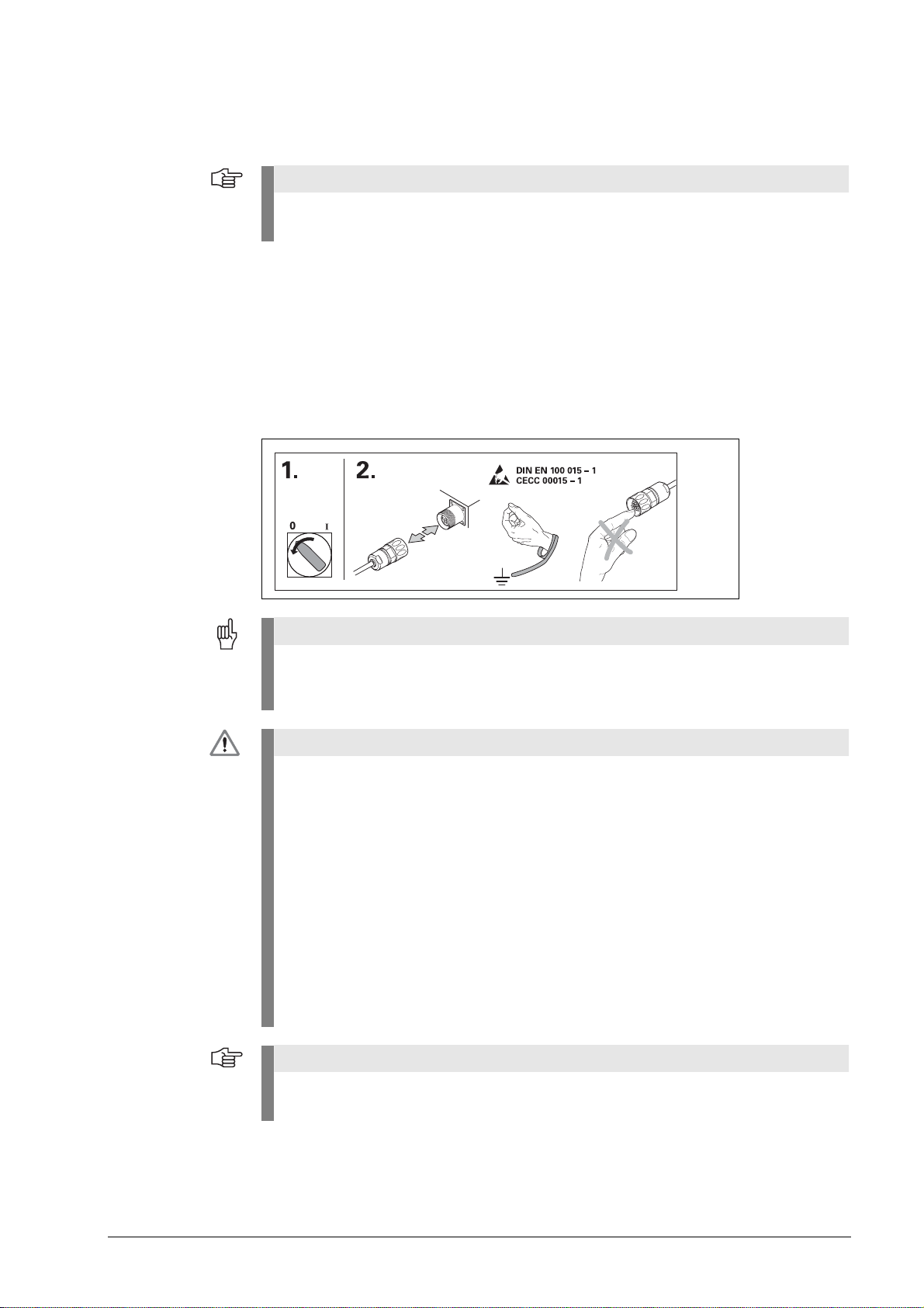
Before you integrate the test units into the position control loop of an NC controlled
machine tool make sure that
1. the machine is switched off!
2. all connectors are disengaged!
Observe the ESD precautions!
Make sure that the connector contacts are clean!
3. Reestablish all required connections and secure them mechanically.
Make the required settings on the PWM.
Switch the machine and the control back on again.
Check whether the machine axis can be traversed in a controlled manner.
During the start-up phase of the machine, the emergency stop button must be accessible
in time.
Do not operate defective units!
No persons are permitted in the traverse range of the machine.
Do not change any parameters or encoder voltages at the test units while the machine tool
is moving and a test unit is connected to the position control loop!
Changed parameters must be reset to their original values.
Ensure that vertical axes cannot fall down!
The ATS software offers the possibility of storing and editing machine-specific or
equipment-specific information in the customer’s memory area. The data may comprise
safety-relevant information.
When servicing, please take care to adjust this memory area. Noncompliance with this
warning could result in damage to the machine or in personal injury.
When troubleshooting always contact the machine tool builder for information (e.g. meaning
of the data in the OEM memory).
Support is provided by HEIDENHAIN Traunreut or by the HEIDENHAIN agencies, see
"Contacts" on page 243.
6 HEIDENHAIN ATS Software User's Manual
Page 6

1.3 Information on the IK 215 adjusting and testing package
Note
The IK 215 Adjusting and Testing Package serves to diagnose and adjust HEIDENHAIN encoders
with absolute interfaces.
The IK 215 adjusting and testing package comprises:
IK 215 interface card for installation in a PCI expansion slot of a personal computer
Adjusting and Testing Software (ATS)
with integrated local encoder database for automatic encoder identification
Standard adapter cables for common testing procedures
Other adapters and adapter cables are available (see table).
The PWM 20 with expanded scope of functions replaces the IK 215.
As compared to the PWM 20, the IK 215 does not support the following functions:
- Incremental interfaces (1 Vpp, 11 µApp, TTL, etc.)
- DRIVE-CLiQ from SIEMENS
- Measuring in feed-through mode
November 2014 General information 7
Page 7

1.4 IK 215 adjusting and testing package (ID 547858-xx); items supplied
The packages 1 and 2 are included in delivery.
Package 1: ID 527367-01 Package 2: ID 658110-01
Package 1 + package 2: ID 547858-xx
Package 1 IK 215 ID 527367-01
Qty. Designation ID
1 IK 215 PCI board 386249-02
1 ATS CD ROM de/en software version 3.0.xx 539862-23
1 IK 215 Operating Instructions 549369-91
Package 2 PWM 20 / IK 215 accessories kit
for absolute encoders ID 658110-01
Qty. Designation ID
1 Benutzer-Handbuch ATS-Software PWM 20/IK 215 de 543734-xx
1 User’s Manual ATS Software PWM 20/IK 215 en 543734-xx
1 Adapter cable (with incremental signal) for IK input, 15/17-pin; D-sub/M23; 2 m 324544-02
1 Adapter cable for LC 18x scanning unit, 12/17-pin; 3 m 369124-03
1 Adapter cable for LC 48x scanning unit, 12/17-pin; 3 m 369129-03
1 Adapter cable for IK input, 15/8-pin; D-sub/M12; 2 m 524599-02
1 Adapter cable for LC xx3, LC xx5, LC 20x scanning unit, 14/17-pin; M12/M23; 3 m 533631-03
1 Adapter cable for RCN 82xx Ultra Lock, 12/17-pin; M12/M23 643450-03
8 HEIDENHAIN ATS Software User's Manual
Page 8

1.5 Information on the PWM 20 encoder diagnostic kit, ID 759251-xx
Note
The PWM 20 encoder diagnostic kit serves to diagnose and adjust HEIDENHAIN absolute and
incremental encoders with absolute and incremental interfaces.
The PWM 20 encoder diagnostic kit comprises:
PWM 20 test unit for direct connection to a laptop/PC via USB interface
ATS Adjusting and Testing Software on CD with integrated local encoder database for
automatic encoder identification
Standard adapter cables for common testing procedures
Case for testing equipment
Other adapters and adapter cables are available (see table).
The PWM 20 test unit is available in three different variants (see tables below):
- PWM 20 basic kit
- PWM 20 basic kit including case (aluminum)
- PWM 20 basic kit including case (aluminum), set of standard adapter cables and
operating instructions
1.6 PWM 20 basic kit, ID 731626-51; items supplied
Basic kit: ID 731626-51
PWM 20 basic kit ID 731626-51
Qty. Designation ID
1PWM 20 731626-01
1 ATS CD ROM de/en software version 3.0.xx 539862-23
1 PWM 20 Operating Instructions 1125089-90
1 USB connecting cable, 2 m 354770-02
1 Power cable, 3 m 223775-01
1 PWM 20 packaging (cardboard box) 730058-01
November 2014 General information 9
Page 9

1.7 PWM 20 encoder diagnostic kit, ID 759251-01; items supplied
The packages 1 and 2 are included in delivery.
Package 1: ID 759249-01 Package 2: ID 658110-01
Package 1 + package 2: ID 759251-01
Package 1 PWM 20 basic kit including case ID 759249-01
Qty. Designation ID
1PWM 20 731626-01
1 ATS CD ROM de/en software version 3.0.xx 539862-23
1 PWM 20 Operating Instructions 1125089-90
1 USB connecting cable, 2 m 354770-02
1 Power cable, 3 m 223775-01
1 Case for testing equipment 785241-01
Package 2 PWM 20 / IK 215 accessories kit for absolute encoders ID 658110-01
Qty. Designation ID
1 Benutzer-Handbuch ATS-Software PWM 20/IK 215 de 543734-xx
1 User’s Manual ATS Software PWM 20/IK 215 en 543734-xx
1 Adapter cable (with incremental signal) for IK input 15/17-pin; D-sub/M23; 2 m 324544-02
1 Adapter cable for LC 18x scanning unit, 12/17-pin; 3 m 369124-03
1 Adapter cable for LC 48x scanning unit, 12/17-pin; 3 m 369129-03
1 Adapter cable for IK input, 15/8-pin; D-sub/M12; 2 m 524599-02
1 Adapter cable for LC xx3, LC xx5, LC 20x scanning unit, 14/17-pin; M12/M23; 3 m 533631-03
1 Adapter cable RCN 82xx Ultra Lock 8/17-pin; M12/M23 643450-03
10 HEIDENHAIN ATS Software User's Manual
Page 10

2 Optional cables and pin layouts
2.1 For optional cables and adapters as well as all pin layouts refer to the User's Manual "Cable and Connection Technology" ID 1117945-xx for PWM 20 (IK 215)!
This User's Manual can be downloaded from the HEIDENHAIN website, see:
www.heidenhain.de/Documentation and Information/Software/Download Area/Diagnostic Set/
PWM/Documentation.
November 2014 Optional cables and pin layouts 11
Page 11

2.2 Scope of functions of the ATS software 3.0
12 HEIDENHAIN ATS Software User's Manual
Page 12

3 Commissioning
Note
Note
Note
3.1 System requirements
IBM PC or 100 % compatible PC
Dual-core processor with a clock frequency > 2 GHz
RAM > 2 GB
Windows XP, Vista, Windows 7 and 8 (32 / 64 bits) operating system
Free space on hard disk > 200 MB
If these requirements are not met, this may lead to very slow data processing or even to
error messages of the ATS software, indicating that certain functions cannot be performed.
A computer with USB interface 2.0 and ATS software is required to run the PWM 20.
System requirements for PWM 20 and IK 215: see respective operating instructions.
3.2 Description of the hardware
The phase-angle measuring unit PWM 20 or the PCI interface card IK 215 are required to run the
ATS software.
The PWM 20 replaces the IK 215 entirely. PWM 20 + ATS V2.4 feature all functions of the
IK 215. Improvements of the ATS software functions are focused on the PWM 20. Certain
functions - such as inspection of incremental and DRIVE CLiQ interfaces, feed-through mode
and various mounting wizards - are only supported by the PWM 20.
For more information on specifications, supported interfaces, hardware installation,
etc., please refer to the respective commissioning instructions.
After using the device, attach the protective caps to protect the electronics and the
connector contacts from electrostatic charge and from contamination!
November 2014 Commissioning 13
Page 13

3.3 Installing the ATS software
Note
A CD-ROM with the required software is among the items supplied. The current ATS software
can also be downloaded from www.heidenhain.de. The software is updated regularly.
To install the ATS software, insert the supplied CD into your CD-ROM drive or run the
"setup.exe" file downloaded from the Internet. Follow the instructions of the installation wizard.
If the setup wizard does not start automatically, please start "setup.exe" manually. Before you
start the installation, please read the Release Notes. After successful completion of the
installation, the icon of the ATS software appears on the desktop.
Installation sequence:
8 If you use the PWM 20, install the ATS software first.
8 Connect the PWM 20 to the laptop/PC with a USB cable.
8 Switch on the PWM 20. (You may be prompted to install the drivers.)
8 Start the ATS software.
The PCI card must be installed, if you use the IK 215.
8 Switch on the computer (you may be prompted to install the drivers) and start the ATS
software.
If you have downloaded the software from www.heidenhain.de, the device drivers are not
installed automatically. In this case, the testing device does not work, and the ATS software
generates an error message. Follow the instructions of the Windows operating system to
install the drivers by hand. You will find the required drivers in the folder 539862xx/FILES/
Drivers of the ATS software package.
3.4 Uninstalling the ATS software
The software can be uninstalled in different ways:
Start the ATS Uninstall Routine via the corresponding Windows button.
Via the "Control Panel" --> "Software" operating system function.
Restart the "setup.exe" of the ATS software; follow the installation wizard and
select the "Remove" option.
14 HEIDENHAIN ATS Software User's Manual
Page 14
3.5 Calibration
Calibration label
on PWM 20
In general the PWM is maintenance-free, since it does not contain any components that are
subject to wear.
To ensure exact and correct operation we recommend that you send the PWM to the calibration
service of HEIDENHAIN Traunreut every two years.
Calibration date
Next recommended
calibration date
November 2014 Commissioning 15
Page 15

3.6 Configuration
8 Start the ATS software.
8 Select the "Configuration" group.
In the "Configuration" group you can make the following settings:
Configure hardware
Language selection
Manage product keys
16 HEIDENHAIN ATS Software User's Manual
Page 16

3.6.1 Configure hardware
Note
1 PCI bus number and the PCI device number of the installed testing device
2 Serial number of the testing device
This function scans the computer and lists the hardware that was found.
8 Select the desired testing device from the list.
8 Confirm with OK to return to the previous screen.
The serial number is required to generate a product key.
November 2014 Commissioning 17
Page 17

3.6.2 Language selection
1 Select German or English
8 Set the operating language.
8 Confirm with OK to return to the previous screen.
18 HEIDENHAIN ATS Software User's Manual
Page 18

3.6.3 Manage product keys
Note
In addition to the function groups and functions of the ATS software (see chapter “Incremental
interfaces” on page 25) HEIDENHAIN reserves additional special functions (e.g. for the
HEIDENHAIN Service) that can be activated by product keys.
The product key generated by HEIDENHAIN is linked to the serial number of the hardware.
The special functions cannot be transferred to other hardware by entering the product key!
1 Input box for product key
2 Serial number of the hardware
3 Display field for new optional function groups
Example: Entering a product key
An optional function is enabled by HEIDENHAIN Traunreut. The product key is generated and
sent by e-mail.
November 2014 Commissioning 19
Page 19

8 Click "Add" to activate the product key.
Note
The "Add" key becomes active, when the correct code is entered. Input errors are reported
as error messages.
1 Serial number (SN) of installed PWM 20
2 <Delete
> removes the product key.
3 Active product-key options
20 HEIDENHAIN ATS Software User's Manual
Page 20

8 Click "Close" to terminate product-key entry.
Note
The product-key functions only appear in the ATS main menu after the connection to the
encoder has been established.
November 2014 Commissioning 21
Page 21

3.6.4 Display of software and database versions
To display the installed versions of the ATS software and the database proceed as follows:
3.6.5 Finding the documentation (Help files) of the ATS software
The documentation of the ATS software is available in the "Help" menu in PDF format.
22 HEIDENHAIN ATS Software User's Manual
Page 22

3.6.6 Updates of the ATS help files (PDF file)
Note
The help files are updated for every software update (once a year) and are included in the
software package. If changes or corrections are required in-between, we make the updated
instructions available on our website www.heidenhain.de (Documentation and information /
Software) from where you can download them.
If you want to update one of the four help files of the ATS software, you have to rename the
"new" PDF file to the name of the previous file. (Example: If the name of the old document is
um.pdf, the new document must be renamed to um.pdf.)
In the program directory where there is the ATS software (example: hard disk C:/Programs(x86)/
HEIDENHAIN/ATS/doc/de or en), replace the existing PDF file by the file you have renamed. The
old file will be overwritten.
The names of the PDF help files (cct.pdf, i.pdf, oi.pdf and um.pdf) must always be the same
in both languages (de and en).
November 2014 Commissioning 23
Page 23

24 HEIDENHAIN ATS Software User's Manual
Page 24

4 Identifying encoder output signals (encoder interfaces)
Note
Note
4.1 Incremental interfaces
Determine interface from encoder designation
The identification of the interface type applies to standard HEIDENHAIN encoders.
Deviations from the designation structure are possible (in particular with customer-specific
encoders).
Other identifiers
A 9-pin M23 connector always means an 11 µApp interface.
Encoders connected to the encoder inputs of EXE interpolation electronics are always
11 µApp encoders.
Encoders connected to the encoder inputs of IBV interpolation electronics are always
1 Vpp encoders.
For encoders with D-sub connectors no conclusions can be made about the interfaces.
November 2014 Identifying encoder output signals (encoder interfaces) 25
Page 25

4.2 Absolute interfaces
Encoders that have a 'C' or a 'Q' in their names use an absolute interface (EnDat or SSI).
There are EnDat encoders with and without incremental A/B sinusoidal signals.
The order designation indicates whether an encoder outputs incremental signals:
EnDat 21 without incremental signals
EnDat 22 without incremental signals
EnDat 01 with incremental signals A/B 1 Vpp
EnDat 02 with incremental signals A/B 1 Vpp
EnDat Hx with incremental signals HTL (as of 2014)
EnDat Tx with incremental signals TTL (as of 2014)
x designates: a = 2-fold interpolation
b = without interpolation
c = scanning signals x2
Also see "Interfaces of HEIDENHAIN Encoders“ brochure, ID 1078628-xx.
26 HEIDENHAIN ATS Software User's Manual
Page 26

5 Software description
5.1 Operational design
The ATS software runs by a dynamic context menu. The function menu contains the function
groups that are available for the connected encoder. Depending on the encoder, the supported
function groups / functions are displayed.
Example:
LC 183 encoder connected and activated.
Function group "Diagnostics" with two active functions ("Absolute-incremental deviation" and
"Online diagnostics").
Explanation of the display
1 Selected function pointer (< )
2 Function group
3 Function
4 Connected encoder
5 ID number
6 Power supply symbol:
Encoder power supply OFF (green)
Encoder power supply ON (red)
November 2014 Software description 27
Page 27

5.2 Setting up a connection to the encoder
Note
8 Connect the encoder to the test unit with an adapter cable.
Adapter cables: See User's Manual "PWM 20 Cable and Connection Technology".
This User's Manual can be downloaded from the HEIDENHAIN website, see:
www.heidenhain.de/Documentation and Information/Software/Download Area/Diagnostic
Set/PWM/Documentation.
8 Double-click "Connect encoder" in the ATS main menu.
The "Encoder selection" window offers two possibilities of powering the encoder and setting the
encoder interface:
1 Automatic encoder identification by entering the ID of the encoder (mandatory for absolute
encoders)
2 The manual settings are only used, if no encoder ID is available (ID plate missing or illegible;
encoder not in the ATS encoder database).
28 HEIDENHAIN ATS Software User's Manual
Page 28

3 Select "Use power supply from subsequent electronics", if the PWM 20 is in feed-through
Note
Note
DANGER
Note
mode and supposed to be powered from the subsequent electronics.
Exception: Do not set the checkmark for the feed-trough mode with SA 100 / SA 110!
The subsequent electronics cannot supply power due to the potential segregation of the
SA 100 / SA 110.
The PWM is powered by the subsequent electronics.
(PWM 20 in feed-through mode)
"Use power supply from subsequent electronics" is only required for the feed-through mode
of the PWM 20. This means that the checkmark may only be set, if the PWM 20 is
connected to the control loop between the control and the encoder (closed loop; X2 OUT
connected to subsequent electronics) without an SA 100 / SA 110.
HEIDENHAIN recommends automatic connection by entering the ID number.
Automatic connection through entering the encoder ID is mandatory for feed-through
mode at axes with absolute encoders!
The relevant encoder data is read from a database. This database is part of the ATS
software.
The encoder database contains all ID numbers and variants of the encoders that existed
when the ATS software was released.
The database is updated about every six months.
You will find the most recent data at www.heidenhain.de.
If the manual setting of the encoder parameters does not match the connected encoder,
the encoder, the IK 215, the PWM 20 or the computer may be damaged.
For the encoder data, please refer to the respective mounting instructions or machine
documentation. Contact the machine manufacturer or the HEIDENHAIN Service.
Encoder connection
Please ensure that the correct supply voltage is selected to avoid damage to the encoder.
The cable between the encoder and the PWM 20 must not be connected or disconnected
while under power. Otherwise the encoder and the PWM 20 might be damaged.
Check whether the cable between the encoder and the PWM 20 is correctly wired.
The pin layout of the encoder is included in the specifications. The pin layouts of the connecting
cables are described in the catalog. An incorrectly wired connecting cable might damage the
encoder and the PWM 20.
November 2014 Software description 29
Page 29
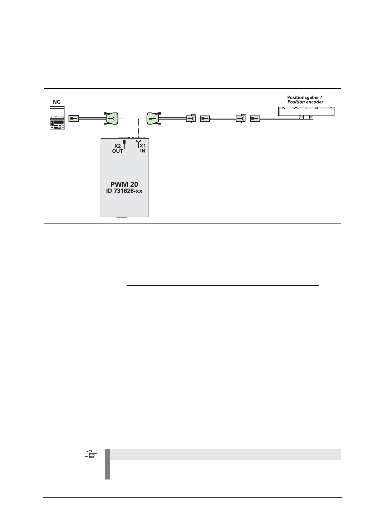
5.2.1 Feed-through mode
Note
"´Feed-through" mode means connecting the PWM 20 into the control loop of an NC-controlled
machine.
For diagnosing, the PWM 20 can be integrated into the control loop of an NC controlled
machine tool via adapter cables at the encoder input X1 and the encoder output X2.
For the feed-through mode the power supply must be switched to the subsequent electronics
in the ATS software.
Set the checkmark in feed-through mode only.
If no subsequent electronics is connected, the encoder is not powered (error message).
The feed-through mode is supported as of the software version 2.6. We recommend always
using the most recent software version (see www.heidenhain.de).
The feed-through mode cannot be used for all interfaces supported by the ATS.
In principle, the following interfaces allow for feed-through mode:
EnDat, Fanuc, Mitsubishi, 1 Vpp, TTL, 11 µApp
EnDat/Fanuc/Mitsubishi
Metallic isolation is possible with the service adapters SA 100 and SA 110.
No metallic isolation, if the measurement is conducted with the PWM 20 only.
For encoders that also support incremental signals, the incremental signals can now also be
displayed and evaluated.
EnDat 2.1
Normally, the only communication over the EnDat interface takes place during the start-up stage
of the NC (interrogation and transfer of the absolute position data):
"Listening in" on the EnDat communication is not possible. (The synchronization time is too
short for the PWM 20.)
The 1 Vpp signals A and B can be displayed.
SIEMENS NC controls currently use EnDat 2.1 with A/B signals and do not support the
monitor function!
30 HEIDENHAIN ATS Software User's Manual
Page 30

EnDat 2.2
Note
DANGER
Communication takes place continuously. However, there is no prescribed communication
pattern. Instead, every OEM determines the sequence of EnDat communication on his own.
No universal “listening in” on the communication is possible.
The monitor function is only possible, if the valuation numbers for online diagnosis
are included in data transfer. (The following controls support the monitor function:
TNC 620, TNC 640, iTNC 530 [as of NC-SW 34049x-04], iTNC 530 HSCI with diagnostic
function and DRIVE-DIAG.)
Synchronization with communication may take some time.
1 Vpp
No metallic isolation, if the measurement is conducted with the PWM 20 only.
Metallic isolation is possible with the SA 100.
The PWM 20 picks off the signals; without 120-ohm signal termination.
The limit frequency is influenced by the test setup (adapter cable, etc.)
11 µApp
The line is interrupted in feed-through mode, i.e. the PWM 20 has an 11 µApp receiver and
reproduces the (emulated) input signals at the 11 µApp output.
The limit frequency is influenced by the test setup (adapter cable, etc.)
Not yet approved for ATS V2.8. Signal errors may occur!
TTL
Without PWT switchover:
The PWM 20 picks off the RS-485 signals, i.e. a standard RS-485 receiver without 120-ohm
termination is connected to the lines.
Automatic connection through entering the encoder ID is mandatory for feed-through
mode at axes with absolute encoders!
Incremental interfaces also permit manual connection by selecting the interface in
feed-through mode.
If the feed-through mode is not used, absolute and incremental encoders can be
connected manually.
However, automatic connection via the ID number is recommended!
Testing cables for feed-through mode are not suitable for regular machine operation.
Due to the great variety of machine designs and their grounding variants it is not
possible to exhaustively test all testing cables.
It is absolutely necessary that you check the safe and proper function of the testing
cables for every test situation!
Uncontrolled axis movements cannot be ruled out when working with testing devices
and cables in feed-through mode.
Example for machine axes with absolute encoders:
Determine the encoder ID with the PWM 20 before feed-through operation (no axis
movement required).
Automatic connection through entering the encoder ID is mandatory for feed-through mode at
axes with absolute encoders. However, the ID is not known and the encoders are not visible
under their covers.
The ATS software can read out and display the encoder ID.
November 2014 Software description 31
Page 31

Procedure:
DANGER
Note
1. The PWM 20 encoder output (OUT) must not be connected!
2. Connect the absolute encoder to the PWM input (IN) using a suitable adapter cable,
connect the ATS software by hand and note down the encoder ID displayed at the
lower right (see “Setting up a connection to the encoder”).
3. Disconnect the ATS from the encoder.
4. Use the appropriate testing cable to connect the PWM 20 output (OUT) to the control
(which is switched off) for feed-through mode.
5. Connect the ATS software automatically with the ID that was displayed before.
Reason: The terminating resistors of the PWM 20 encoder output (OUT) block the measuring
function of the ATS.
If the PWM 20 output (OUT) is used for manual connection, the transfer function of absolute
encoders is blocked.
Integrating the PWM 20 into the control loop influences the supply voltage
and grounding conditions (see Installation and commissioning instructions,
ID 729905-91).
The feed-through function must be handled with great care and caution!
No persons are allowed within the working range of the machine!
Ensure that vertical axes cannot fall down!
Do not disengage any connecting elements during the measurement!
Move the machine axis to the middle of the traverse range before you connect the
PWM 20!
When you have connected the PWM 20 into the control loop of the machine, check
whether the axis concerned can be traversed in a controlled manner.
One operator must be at the EMERGENCY STOP switch to make sure that the
machine can be switched off at any stage of this "setup phase"!
Possible
- Uncontrolled machine movement
- Machine switches off (EMERGENGY STOP)
- Machine axis drifts
- Machine axis traverses at rapid traverse
Observe the safety precautions in the PWM 20 Operating Instructions
(ID 1125089-90).
HEIDENHAIN recommends running the feed-through mode with floating supply with the
service adapters SA 100 / SA 110.
axis behavior caused by grounding problems:
32 HEIDENHAIN ATS Software User's Manual
Page 32

Power-on sequence for feed-through mode
DANGER
Absolute interfaces (EnDat, Fanuc, ...)
1. Switch on the PWM 20.
2. Start the ATS software.
3. Set the checkmark "Use power supply from subsequent electronics
(= feed-through mode).
4. Connect the absolute encoder by entering its ID (the ID is mandatory!)
5. Switch on the subsequent electronics.
Incremental interfaces (1 Vpp, 11 µApp, ...)
1. Switch on the PWM 20.
2. Start the ATS software.
3. Set the checkmark "Use power supply from subsequent electronics
(= feed-through mode).
4. Connect the incremental encoder by entering its ID or manually by
selecting the interface.
5. Switch on the subsequent electronics.
Encoder output
The encoder input X1 of the PWM 20 is electrically connected with the encoder output X2.
The signals and the pin layout at the output correspond to the respective signals at the input.
There is no metallic isolation of the signals.
The supply and sensor lines are switched via the ATS software (as of ATS V2.6) depending
on the respective mode of operation and can be connected (see examples).
It is always ensured that the supply voltage generated by the PWM 20 is not present at X2.
Example 1:
PWM 20 in feed-through mode (encoder
powered by subsequent electronics) or
ATS software not started
Example 2:
PWM 20 powers the encoder via X1
November 2014 Software description 33
Page 33

5.2.2 Automatic encoder identification by entering the ID
Note
1 Input field for ID
2 The encoder was identified.
3 Input field for the "feed-through mode" (measurement in control loop of machine axis)
Use the ID of the scale housing for sealed linear encoders (e.g. LC), and the ID of the
scanning head for exposed linear and angle encoders (e.g. LIC).
The ID can also be entered without the hyphen (e.g. 36856306).
If the encoder cannot be identified, the software enters three question marks "???".
(See chapter “Manual encoder selection” on page 37.)
34 HEIDENHAIN ATS Software User's Manual
Page 34

Switching on the power supply for the encoder
Note
8 When you click "Connect", the power supply for the connected encoder is switched on.
Switching off the encoder power supply
8 To switch off the power supply double-click "Disconnect encoder"; now the encoder cable
may be disconnected.
6 Encoder type and ID
7 Power supply symbol:
Encoder power supply OFF (green)
Encoder power supply ON (red)
Never disconnect any connectors while the encoder is under power.
If the ATS software has found a difference between the ID number typed in and the ID number
saved in the encoder memory, an error message is generated. Confirm this message with "Yes"
(recommended). Now, the ATS software connects to the encoder parameters.
November 2014 Software description 35
Page 35

8 When you click the "Yes" button the encoder ID is used (ID of the scale housing).
Note
Attention
Note
8 When you click "No" the ID that was entered is used.
8 ID check message
This message is displayed when the ID of the LC is incorrect, for example.
If the ATS software finds differences between the characteristics of the encoder and the data in
the database, the following "Encoder selection" screen may be displayed.
In this case, it is recommended to check the ID of the connected encoder and whether it was
entered correctly.
If wrong data from the encoder memory ("Encoder" button) or the encoder database
("Database" button) is used for connecting, the encoder, the test unit or the computer may
be destroyed.
The tolerance ranges of the wizards may be influenced as well.
Please contact HEIDENHAIN if it is impossible to determine the encoder parameters.
36 HEIDENHAIN ATS Software User's Manual
Page 36

5.2.3 Manual encoder selection
Note
Attention
If it is impossible to identify the encoder type (ID label missing or illegible), or if the encoder is
not in the ATS database, most EnDat interfaces offer the possibility of entering the encoder data
by hand.
The function below serves to read out the encoder ID from the encoder memory and display it
on the screen (lower right).
With this ID displayed, "automatic" encoder identification can be performed.
The encoder interface must work properly for this purpose!
Regarding the encoder data, please refer to the
Encoder mounting instructions,
HEIDENHAIN sales literature,
or contact the HEIDENHAIN Service.
Observe the warnings!
8 The "Connect encoder" button opens the "Encoder selection" box.
November 2014 Software description 37
Page 37

8 In the Encoder selection box, click "Manual Settings".
Note
Attention
This option is only recommended to advanced users!
Incorrect entries may cause damage to the scanning unit, the test unit or the computer.
The setting of the encoder power supply is of particular importance!
Observe the warnings!
38 HEIDENHAIN ATS Software User's Manual
Page 38

8 Clicking the "Forward >" button opens the encoder data screen (power supply, encoder
Note
interface).
1 Input of encoder power supply
2 Input of voltage readjustment over sensor lines
3 Input of data interface supported by the ATS software
Currently, the ATS software 3.0 supports the following encoder interfaces:
EnDat
1 Vpp
TTL
HTL
HTLs (without inverted signal)
DRIVE-CLiQ
SSI
Fanuc
Fanuc ALPHA i
Mitsubishi
Yaskawa
Panasonic
11 µApp
SSI+HTL
3 Vpp
25 µApp
To compensate for voltage drops on the lines between test unit and encoder, HEIDENHAIN
recommends activating "Adjust voltage over sensor lines" (no. 2). When you select the
encoder through its ID number, voltage adjustment is automatically activated.
November 2014 Software description 39
Page 39

4
An ATS code only has to be entered if, for example, no mounting wizard is available for
selection on the basic screen after automatic connection with encoder ID.
Normally, the required functions are taken into account in the encoder database and are
assigned to the encoders.
In special cases (e.g. pre-series encoders) the database may not be up-to-date, and such
encoders cannot be mounted as long as there is no "mounting wizard". For these
exceptions, an ATS code can be entered by hand on the basic screen to display the
"Mounting" function.
Display after the "ATS Code" button was pressed:
The ATS code can be requested from HEIDENHAIN for the encoder ID concerned.
Prompt for entering the code:
8 Clicking the "Forward >" button opens an overview of the data you have entered.
40 HEIDENHAIN ATS Software User's Manual
Page 40

Attention
Observe the warnings!
Note
If the selected supply voltage is too high (e.g. 24 V), the electronics of an encoder operating
with 5 V will be destroyed.
Check the displayed values.
8 After you click the "Connect" button, the connected encoder is supplied with power.
Typical error message of purely serial EnDat 2.2. encoders without incremental signals.
Confirm this message with "Yes" to connect without incremental signals.
The EnDat designation is printed on the ID label.
November 2014 Software description 41
Page 41

If this error message is generated, the voltage drop caused by the cable length
>
(for LC approx. 5 m) is probably too high.
8 In this event voltage adjustment needs to be activated.
The function group window is displayed. The encoder ID appears at the lower right.
Display of encoder model and ID number
The red symbol means that the encoder is under power.
8 Write down the encoder ID!
42 HEIDENHAIN ATS Software User's Manual
Page 42

8 In a next step perform "automatic" encoder identification by entering the displayed encoder ID.
Note
(See chapter “Automatic encoder identification by entering the ID” on page 34.)
In general, the ATS software automatically loads the ID in the "ID number" field, i.e. it is not
necessary to enter the ID by hand.
Correct database connection with the proper parameters always requires the ID
of the encoder (printed on the scale housing)!
November 2014 Software description 43
Page 43

5.3 Basic functions
Note
Display and functions may vary depending on the product key and the connected encoder
model!
44 HEIDENHAIN ATS Software User's Manual
Page 44

5.3.1 Position display
Note
Note
1 Absolute encoder position
2 Incremental current count
3 Binary display of the absolute position
(1:1 display of the transferred position data without any conversion)
1 means bit 1 = LSB (least significant bit)
4 Yellow arrow = one step back
For encoders with purely serial data interface (e.g. EnDat 2.2, Fanuc) the incremental
position is not displayed.
The number of absolute positions [bits] depends on the connected encoder.
November 2014 Software description 45
Page 45

Status display Each time position data is transferred, status information is included and evaluated.
Depending on the encoder model, information on encoder alarms and warnings and on the
quality of the incremental signal are available.
1 The encoder status is displayed in shortened form (group signal) in the lower area of the
position display screen as colored LED symbols.
2 Use the magnifying glass symbol to display detailed information.
The EnDat interface allows for extensive monitoring of the encoder. An alarm becomes active
if there is a malfunction in the encoder that is presumably causing incorrect position values.
Some examples of alarms:
Failure of the light unit
Encoder signal amplitude too small / too large
Incorrect position value
Supply voltage too high / too low
Current consumption is excessive
Warnings indicate that certain tolerances of the encoder were reached or exceeded
(e.g. speed, control reserve of the light unit), but the position value is not incorrect. If a warning
is displayed the encoder concerned should be inspected or exchanged as soon as possible in
order to avoid downtimes.
Some examples of warnings:
Frequency exceeded
Temperature exceeded
Control reserve
Illumination
etc.
46 HEIDENHAIN ATS Software User's Manual
Page 46

1 LED symbols for errors and warnings
Note
Green symbol = OK
Red symbol = Error / warning
Group signal; at least one "error" present!
Display detailed status information
November 2014 Software description 47
Page 47

Details of encoder status:
Attention
Note
Reset errors / warnings
Please reset the errors and warnings before starting!
After you connect the encoder by the ATS software, errors caused by encoder components
may be displayed, although actually there is no malfunction.
If the error messages cannot be reset and new error messages are generated, the encoder
needs to be replaced or repaired.
A given encoder does not necessarily support all monitoring functions. The information
which errors and warnings an encoder supports can be read out and displayed with the
following ATS software function.
48 HEIDENHAIN ATS Software User's Manual
Page 48

8 Select "Display encoder memory" from the basic functions list.
The encoder configuration window is activated.
8 Press the "function-specific view" button (display in plain language).
8 Press the "EnDat" button.
The encoder data is transferred from the encoder memory to the test unit.
November 2014 Software description 49
Page 49

8 Open the directory tree "Parameters of encoder manufacturer".
Note
Scroll down in the directory and open the directory branches
Support of error messages
or
Support of warnings
Supported error messages and warnings are distinguished by "Yes".
For detailed information on the encoder status please refer to the EnDat interface manual.
50 HEIDENHAIN ATS Software User's Manual
Page 50

EnDat 2.2 status
Note
display
A yellow "Busy" symbol indicates access to the memory of the encoder EEPROM (12 ms max.)
Otherwise, the "Busy" LED is gray; it is used for forced dynamic sampling and for encoders with
functional safety.
The "Reference mark" LED shows whether the EIB has detected the reference mark signal.
(This function is only used in connection with the EIB interface converters.) If an EIB electronics
is connected and with incremental encoders, the LED is displayed in gray color and turns yellow
as soon as the reference mark has been traversed.
The "Reference mark" LED of absolute encoders is always yellow.
For encoders without incremental signals the incremental status is masked out!
This status display is required for synchronization with the reference mark when using
HEIDENHAIN EIB interface electronics. Only after the reference mark was detected is the
incremental encoder "quasi-absolute".
November 2014 Software description 51
Page 51

Detailed display of
Note
encoder status
EnDat 2.2
Operating status error sources
The function "operating status error sources" provides detailed information on errors and is an
expansion of the EnDat 2.2 error register under operating conditions.
It is accessed via the EnDat additional datum. Its advantages are fast access in a closed loop and
the differentiation, whether the error was caused by the single-turn or the multi-turn component
of position value formation.
Operating status error sources are only supported by EnDat 2.2.
A given encoder does not necessarily support this function. The error messages are
encoder-specific!
Whether this function is supported and which error sources it comprises is defined in the
Encoder configuration [encoder data]/Manufacturer parameters EnDat 2.2/Support of
operating status error sources.
Press the "Detailed status display" button to call the function.
8 Press the "Read operating status error sources" button.
52 HEIDENHAIN ATS Software User's Manual
Page 52

Display if the encoder does not support the "Operating status error sources" function:
Display after "OK" was pressed:
Display if the encoder supports the "Operating status error sources" function; details on errors:
November 2014 Software description 53
Page 53

Which status error sources the encoder supports is stored in the "Parameters of the encoder
manufacturer for EnDat 2.2" in the encoder memory.
Example:
Connection to EIB interface electronics
The EIB (Extended Interface Box) interpolates the sinusoidal output signals (1 Vpp) of
incremental HEIDENHAIN encoders and transforms them into absolute position values.
After the reference mark has been crossed, the position value is defined with respect to this
unique (absolute) position.
Permitted output signal interfaces:
EnDat 2.2
Fanuc serial interface
Mitsubishi high speed interface
EIB 192
54 HEIDENHAIN ATS Software User's Manual
Page 54

EIB 392
Note
To check the EIB, a suitable incremental encoder must be connected to the EIB input (follow the
EIB operating instructions).
8 Plug the EIB and the encoder to the PWM 20 or IK 215 and connect them by means of the
ATS software.
Use the ID of the EIB for connecting to the ATS software.
8 In the "Basic functions" main menu click the "Position display" function.
A warning (red LED) appears in the display field for the EnDat status.
8 Click the "Detailed status information" button.
November 2014 Software description 55
Page 55

Position display if an EIB 192 with Fanuc interface is connected.
The absolute position is invalid, as the reference mark was not traversed yet (LED gray) and the
Alarm LED is red.
The warning "Bit 4 – Reference mark not traversed" is displayed.
Display for Fanuc: "Error: Bit 2" -> This bit is set when an incremental encoder is switched on!
The "Ref. mark" status is displayed in gray color.
8 Traverse the reference mark(s) of the encoder.
56 HEIDENHAIN ATS Software User's Manual
Page 56

Only after the reference mark has been traversed refer the absolute position values to this fixed
Note
reference point.
As soon as the reference mark has been detected, the "Ref. mark" status display changes to
yellow.
The "Warnings" LED remains red and must be reset by hand.
The reference mark must be traversed before the "Warnings" can be reset.
Position display if an EIB 192 with Fanuc interface is connected.
Same procedure as with EnDat; here, the "Alarm" LED needs to be reset by hand.
November 2014 Software description 57
Page 57

Note
The warning in the Encoder status field can only be deleted by hand after the reference
mark has been detected. For this purpose, press .
This also applies for Fanuc EIB x92F.
8 Warning deleted.
58 HEIDENHAIN ATS Software User's Manual
Page 58

Measured values view
Position view
The measured values are displayed as they are transferred from the encoder.
The measured values are converted into linear [µm] or angular [degrees] data
according to the settings of the encoder parameters.
November 2014 Software description 59
Page 59

Clear incremental
Note
counter
Display for a multiturn encoder:
For encoders without incremental signals the incremental status is masked out!
The incremental counter is set to zero (0.0).
Equate function
The incremental counter loads the absolute position (displays of absolute and
incremental positions are the same).
60 HEIDENHAIN ATS Software User's Manual
Page 60

Synchronization
mode
The absolute and the incremental positions are synchronized with each other at the
counting limits (zero crossover of absolute and incremental tracks).
Synchronization inactive:
Synchronization mode active:
Reversal of counting direction with incremental counting
Example: 13-bit rotary encoder
If the encoder is rotated into the "minus" range, i.e, beyond the zero position, the absolute code
of the absolute track restarts with the highest position value (in the example: 8191), whereas the
incremental counter starts to count backwards, i.e. -1, -2 …
When the synchronization mode is activated, the incremental counter also starts with the
highest absolute value (in the example: 8191).
Counting limit = Absolute value 'Zero' ( )
November 2014 Software description 61
Page 61

Absolute position [bits] display
Note
Attention
DANGER
The displayed value is the position value transferred from the encoder (1:1 display of the
transferred data without any conversion).
The absolute encoder position is displayed as binary value.
Position 1 represents bit 1 which is the LSB (Least Significant Bit) of the position value.
The bit length may vary and depends on the connected encoder.
Example: Rotary encoder with 37 bits
The counting direction for the incremental positions is reversed.
For certain encoders (e.g. SSI rotary encoders) the counting direction of the
incremental counters can be programmed; the ATS software can be adjusted
for parallel measurement.
Datum shift Customer-specific datum shift can be performed with EnDat encoders.
This serves to adapt the encoder (e.g. to capture the rotor position of a synchronous motor) to
the machine/motor individually for each axis.
If you want to repeat (e.g. correct) the datum shift, the current datum shift must be canceled
first!
The datum shift can only be performed correctly while the encoder is in standstill.
An incorrectly set datum (with synchronous motors: field angle) can lead to undesirable
reactions of the motor, including uncontrollability. It might even move in the wrong
direction!
Ensure that vertical or hanging axes cannot fall!
Please contact the machine manufacturer or HEIDENHAIN, if you have any questions.
62 HEIDENHAIN ATS Software User's Manual
Page 62

Set datum
Note
Attention
Note
shift
8 Click the symbol.
There are two types of datum shift:
1. EnDat-compliant datum shift
This type considers the relation of datum and signal period (incremental signal).
After the datum shift the absolute datum will not always be exactly the current position.
The ATS program calculates the new datum such that in relation to the incremental signals
its position corresponds to the EnDat specification, i.e. is as close as possible to the desired
position.
For encoder types "with incremental signals" (interface names EnDat 01 and EnDat 02)
the setting "EnDat-compliant datum shift" must be active.
If you want to repeat (e.g. correct) the datum shift, the current datum shift must be canceled
first!
The checkmark at "Datum shift EnDat-conform" may only be removed for purely serial data
transmission.
November 2014 Software description 63
Page 63

2. Non EnDat-compliant datum shift
Note
Note
An assignment of datum and signal period (incremental signal) is not considered!
This setting is used for purely serial measuring systems (i.e. encoders that do not output any
incremental signals; interface names EnDat 22 and EnDat 21).
8 Set datum "to current position".
Before the datum shift is performed, the measuring system must be positioned to the point
at which the new datum should be set.
8 Set datum "to absolute position".
The desired datum shift can be entered as numerical value into the field highlighted in blue.
The absolute value can be entered in [steps] or in [µm].
8 After you click the "Set" button the datum is saved in the encoder memory.
64 HEIDENHAIN ATS Software User's Manual
Page 64

Cancel datum shift
8 To reset the datum shift to the factory default setting click the button "Undo
datum shift" and confirm the prompt with "Yes".
Check datum shift in encoder memory
In the "Operating parameters" section of the encoder memory you can check the specified
datum shift.
For this purpose the configuration of the encoder must be read out first.
8 Select "Display encoder memory" from the basic functions list.
November 2014 Software description 65
Page 65

8 Press the "function-specific view" button (display in plain language).
8 Press the "EnDat" button ("Load encoder configuration from encoder").
The encoder data is transferred from the encoder memory to the test unit.
8 Open the tree structure of the "Operating parameters" directory.
In the "Value" column of the table you find the datum shift in measuring steps. For measuring
lengths up to 32 bits word 0 and word 1 are used, for measuring lengths up to 48 bits word 2 is
used in addition.
66 HEIDENHAIN ATS Software User's Manual
Page 66

Edit datum
Note
shift value
Manual editing of the datum shift is only recommended to expert users.
To shift the datum, always use the keys "Set datum shift" or "Cancel datum shift" on the
"Position display" screen!
EnDat-compliant datum shift is only taken into account here.
1. Editing in the datum shift line (word 0):
8 Click the datum shift value.
Enter a new value. If you intend to cancel the datum shift, enter the value 0.
To activate the edited datum shift, the encoder configuration must be saved in the encoder.
8 Click the "EnDat" button ("Save encoder configuration in encoder") to open the
window for selecting the memory area.
8 Select the "Operating parameters" memory area.
8 Click the "Transfer" button to save the data in the encoder.
November 2014 Software description 67
Page 67

2. Editing in the datum shift window:
Note
Attention
8 Clicking the button right from "Datum shift value" opens the "Datum shift"
window.
Here the value (decimal/hexadecimal/binary) can be edited; click OK to confirm.
Entering the value 0 cancels the datum shift.
If the datum shift is manually edited in the operating parameters area, the ATS software
does not check, whether the entry value is EnDat-compliant.
8 Click the "EnDat" button ("Save encoder configuration in encoder") to open the
window for selecting the memory area.
8 Select the "Operating parameters" memory area.
8 Click the "Transfer" button to save the data in the encoder.
68 HEIDENHAIN ATS Software User's Manual
Page 68

5.3.2 Incremental signal display
Note
In the basic function "Incremental signal display" the incremental signals A/B are displayed on the
oscilloscope and the signal parameters as bar charts.
The tolerances of the A/B signals can be checked here. A number of settings are available to
adjust the display to the current testing situation.
The oscilloscope function is sufficient for most standard tests. Fast signal changes (error
spikes, noise, etc.) might not be detected!
For this purpose additional testing equipment, such as a PWM 9 and a digital oscilloscope
is required.
8 To select the function, double-click "Incremental signal display".
The "Incremental signal display" is a digital storage oscilloscope that can display the relevant
incremental signals and standard tolerances. The sinusoidal signals A and B can be displayed
as a circle function (x-y graph) or as sine-cosine diagram (y-t graph).
The display type is selected in the setup menu . The diagrams can be saved and printed.
November 2014 Software description 69
Page 69

Circle
Note
diagram (X-Y)
For detailed explanations of terms such as TV1[°], PHA [°], V A/B refer to the section
“Description of the incremental signal display” on page 151.
Signal amplitudes and tolerances are stated in the chapter “Interface description” on
page 209.
In the circle diagram, the inner green circle represents the minimum amplitude, the outer green
circle the maximum amplitude (tolerance range of the amplitude).
Time function (y-t)
70 HEIDENHAIN ATS Software User's Manual
Page 70

Zoom function The oscilloscope display features a zoom function controlled via the left mouse button.
Zooming a detail
Press and hold the left mouse button and – starting at the upper left – draw a square over the
desired area. This area will be magnified.
The zoomed area can be shifted vertically with the mouse wheel and in x-y direction with the
right mouse button.
Unzooming
Press and hold the left mouse button and diagonally move the cursor from the lower right to the
upper left (a short distance is sufficient).
November 2014 Software description 71
Page 71

Save or print oscilloscope display
To activate this function click the screen display with the right mouse button.
In the context menu, select "Save diagram" or "Print diagram" and follow the instructions.
Save diagram: Diagram software TeeChart = independent program integrated into the ATS
software
Examples of what is possible with the "Save" command:
Picture: Change the graphics format (image format [.bmp or .wmf], diagram size and color,
execution, etc.)
Native: Data format binary, text or XML (software development tool for graphics
programming)
Data: Format for data storage (text, XML, HTML, Excel file, etc.; header,
numerical format, tabulators, commas, etc.)
Series: Which of the recorded data are to be used for the diagram? (Select all or
certain data)
Data can be copied [Copy], saved [Save], sent [Send] or displayed [Preview].
72 HEIDENHAIN ATS Software User's Manual
Page 72

In the example below, signal data were transferred in Excel format and an Excel sheet was
created from a defined number of data points (Excel functionality).
The number of data points and the area can be freely selected in Excel (e.g. to document signal
failures or disturbances on the output signal).
November 2014 Software description 73
Page 73

Print diagram
In the Setup column of the diagram software (TeeChart Print Preview = independent program
integrated into the ATS software), you can scale the diagram for printing:
Portrait/landscape (orientation), margins, proportionality, antialiasing and color (smooth) as well
as the background color can be set. Press the Panel key to make further settings.
74 HEIDENHAIN ATS Software User's Manual
Page 74

Characteristics of
Note
Note
the incremental
signals
(bar diagram)
If the signal tolerances are within the specifications (tolerances: see interface description, e.g.
in the product catalog), the bars are displayed in green color; if the tolerances are exceeded the
color changes to red.
The position of the colored markers ("bars") indicates the measured value on the scale. The
current values are also displayed as decimals (in the example: Signal B = 0.56 Vpp; signal is out
of tolerance and therefore displayed in red).
The image below shows the red bars indicating that a tolerance was exceeded.
Red lines on the scale (see frames in the picture below) mark the tolerance range (standard
values).
Information on the scaling and the names of the bars are displayed in context boxes that open
when you position the mouse pointer on a designation of a bar.
Description of the buttons
In the Service option, the following buttons are additionally active:
This buttons opens the "Settings" window.
You can make changes in 5 categories.
Resetting to factory default is not possible!
The next two screenshots of the "Settings" show the default condition (factory setting).
Settings for X-Y display:
November 2014 Software description 75
Page 75

Settings for y-t display:
Diagram view: Select X-Y view or y-t view
Diagram axis ranges: Scaling of the axes
Clear diagram: When the value entered here is exceeded, the diagram data
is deleted (minimum value = 100).
Sampling rate: Sampling rate of the oscilloscope (min. 10 µs,
max. 65535 µs)
Single shot measurement: Number of measuring points for single-shot measurement
Stop measurement
Start measurement
Activate single shot measurement
(When the number of measured values entered in "Settings" is reached,
the screen freezes.)
76 HEIDENHAIN ATS Software User's Manual
Page 76

Tolerances of the
Note
incremental
status display
Error display = "Red LED", if
Amplitude too small: typical 0.20 Vpp (possible as of 0.25 Vpp)
Amplitude too large: typical 1.30 Vpp (possible as of 1.25 Vpp)
Frequency exceeded: > 2.0 MHz possible
The threshold of the incremental status display is not identical with the bar display (red bars).
The red lines on the scaling of the bar display represent the tolerances of the general
specifications of the output signals (sales literature); the incremental status display
corresponds to the functional limit of the encoder!
5.3.3 Display encoder memory
Absolute HEIDENHAIN encoders with EnDat interface feature an internal encoder configuration
memory. The layout of the configuration memory and the meaning of the individual data words
are described in the interface specification entitled "EnDat Interface: Bidirectional synchronous
serial interface for position encoders."
This specification is available from HEIDENHAIN as a separate document.
Therefore, this manual does not provide explanations of the individual memory areas and data
words.
Call encoder configuration
8 Click the function "Display encoder memory".
The encoder configuration window is activated.
November 2014 Software description 77
Page 77

Load encoder
Note
configuration
from encoder
8 Press the "EnDat" button ("Load encoder configuration from encoder").
The encoder configuration is transferred from the encoder memory to the computer.
The encoder data are displayed in a tree structure.
Display of the tree when an EnDat 2.2 encoder is connected:
Display of the tree when an EnDat 2.1 encoder is connected:
These tree views are examples.
The display may vary depending on the encoder and interface specifications and on the
product key used.
Tool bar for encoder configuration
78 HEIDENHAIN ATS Software User's Manual
Page 78

Load encoder configuration from a file
8 When you click this button, the "Open file" box is displayed. Similar to the
Windows Explorer you can, e.g. search for and open backup files.
Only files with the extensions *.edf and *.ecf can be read.
Save encoder configuration to a file
8 This button serves to save the current encoder configuration on your computer.
First, the data needs to be transferred from the encoder to the computer; see
next step.
When the "Save file" window is displayed you can create a new folder to save
the encoder configuration data (backup) on your computer. The data are stored
as x.ecf or x.edf files.
November 2014 Software description 79
Page 79

Load encoder
Note
configuration
from encoder
8 With the button "Load encoder configuration from encoder" the data stored in
the encoder are transferred to the computer, and the tree view of the encoder
configuration is displayed (see sections “Display encoder memory” on page 77
and “Load encoder configuration from encoder” on page 78).
HEIDENHAIN recommends saving the loaded encoder data on a computer.
(See section “Save encoder configuration to a file” on page 79.)
80 HEIDENHAIN ATS Software User's Manual
Page 80

Save encoder
Attention
configuration
in encoder
8 With the button "Save encoder configuration in encoder" an encoder configuration stored in
the computer is transferred to the encoder where it is saved in selected memory areas.
8 After clicking this button you can select the memory area to be transferred in the
"Selection of memory area" window.
8 Click the "Transfer" button to write the "new" data to the selected memory areas.
Data already saved in the encoder will be overwritten! We recommend that you back up the
"old" encoder configuration. (See section “Save encoder configuration to a file” on page 79.)
November 2014 Software description 81
Page 81

Note
Some memory areas may be write-protected (can be seen from Encoder configuration ->
Operating status -> Write protection).
Any attempt to write data to a write-protected memory area generates an error message.
Encoder configuration
8 This button reduces the display of the tree structure to the main directories
(basic view).
View of the encoder configuration
The display of the configuration data consists of two columns. The left side (Entry) shows the
available memory areas in a tree structure. On the right side (Value) the data words assigned to
the selected memory area are displayed. The display may be function-related or data-related.
82 HEIDENHAIN ATS Software User's Manual
Page 82

Function-related view of encoder configuration data
8 When you click this button the data words and values are interpreted according
to the EnDat specification as far as possible, and displayed in plain language.
The function-related view is best suited to check the memory entries.
Data-related view of encoder configuration data
Decimal value display
8 When you click this button the numerical values of the data words are displayed.
November 2014 Software description 83
Page 83

Binary value
Note
display
Hexadecimal value display
This display mode is used in the EnDat interface description.
84 HEIDENHAIN ATS Software User's Manual
Page 84

Edit encoder configuration
8 Use the left mouse button to mark the value to be edited (in the example: Datum shift).
Value can be edited.
Value cannot be edited.
Value cannot be edited, since it is the result of a calculation or it consists of several
words for easy-to-read display (e. g. ID 557 650-06).
The drop-down list opens.
8 Open the editing window by clicking this button (to the right of the drop-down
list).
Second option:
8 Click the arrow to open the list from which you can select predefined
values.
November 2014 Software description 85
Page 85

Third option (no screenshot):
Attention
Attention
8 Select Yes/No
(check mark in check box = yes, check box empty = no)
When you have successfully edited the encoder configuration on your computer, press the
EnDat button to transfer it to the encoder.
Only then will the data in the encoder memory be active. (See “Save encoder configuration
in encoder” on page 81.)
The old data will be overwritten.
We recommend that you back up the "old" encoder configuration!
Set writeprotection for
memory areas
For EnDat encoders there is the possibility of assigning write-protection to memory areas so that
the data are protected from unintended editing. This is necessary, particularly to ensure machine
safety and system reliability.
HEIDENHAIN therefore protects the ”parameters of encoder manufacturer” memory area with
a write-protection bit. Among other information the encoder adjustment data are stored here;
editing these data would render the encoder inoperable.
We recommend setting the appropriate write-protection bit after setting the machine-relevant
parameters in the OEM memory areas and after "datum shift" (operating parameters)!
The write-protection cannot be reset after the encoder configuration was saved in the
encoder.
Only JH Traunreut or an authorized HEIDENHAIN representation can cancel writeprotection!
Example: Setting write-protection
means "YES" = Write-protection set.
8 When you click this button the data is transferred to the encoder memory and
write-protection is active.
86 HEIDENHAIN ATS Software User's Manual
Page 86

5.3.4 Comparing contents of encoder memories
Note
With this function you can compare the configuration of the connected encoder to a reference
file.
This comparison function is only recommended to advanced users!
The encoder to be compared must be connected and identified.
Prerequisite for memory comparison:
The encoder configuration (reference file) which is to be compared must be available on the
computer!
8 Click the function "Comparison of encoder memory".
November 2014 Software description 87
Page 87

The log window ("Protocol") appears, and you are prompted to load the configuration of the
encoder currently connected.
When you click this button, the current configuration of the connected encoder is
loaded and saved in the comparison register 1 (= encoder configuration 1).
The left button loads an encoder configuration (e.g. received by e-mail and saved
in the computer) from a known storage location into the comparison register 1
(= encoder configuration 1).
The right button loads the encoder configuration 2 (= reference configuration )
to be compared into the comparison register 2.
The storage location of this configuration must be known.
8 Clicking this button starts the comparison of the two memories. (This may take
several seconds.)
88 HEIDENHAIN ATS Software User's Manual
Page 88

The differences of the encoder configurations 1 and 2 are entered into the log file.
Note
Additional documentation is required to understand and evaluate the entries!
(EnDat specifications are available on request.)
Original encoders – even with the same ID – always differ from each other, since e.g. signal
compensation values are individually determined and saved for every encoder!
Example of an error message, if encoder configurations cannot be compared (different
EnDat command sets):
8 Click this button to terminate the function and return to the main menu.
November 2014 Software description 89
Page 89

5.3.5 Voltage display
Voltage:
Display of the voltage the test unit provided to power the encoder
90 HEIDENHAIN ATS Software User's Manual
Page 90

Voltage [Remote Sense]:
Note
Note
Operating voltage at the measuring system; voltage drops on the encoder supply lines
are taken into account.
Current:
Display of the encoder current consumption
Power [Remote Sense]:
Power consumption of the encoder
If the encoder does not draw any power, the display changes to red.
"Terminating resistors" key
The "Terminating resistors" key serves to (de)activate the terminating resistors
Z0 = 120 .
(Also see chapter “Interface description” on page 209.)
In general, the terminating resistor is inactive and cannot be switched on, if the
PWM 20 is operated in feed-through mode (closed loop, "Use power supply from
subsequent electronics" checkmark is set).
When the menu is changed, the ATS software again uses its default setting:
- Measurement without feed-through: Terminating resistor active
- Feed-through operation: Terminating resistor inactive
The terminating resistors are active.
The terminating resistors are inactive.
The display may be different, depending on the type of power supply selected and on the
encoders connected.
The displays Voltage [Remote Sense] and Power [Remote Sense] are active, if "Adjust
voltage over sensor lines" was selected in the window for manual encoder selection.
In "closed-loop operation" and when a Service Adapter (e.g. SA 100 or SA 110) is used,
power supply and current consumption of the service adapter (not of the encoder) are
displayed!
November 2014 Software description 91
Page 91

5.4 Add-on info (EnDat 2.2): Temperature display
Note
Display and scope of function may vary depending on the EnDat interface, the product key
and the connected encoder!
Not all encoders support temperature display. From the "Temperature display" icon you can
see, whether the function is available.
8 When you double-click the "Temperature display" button the current temperature values the
of sensors 1 and 2 are displayed.
92 HEIDENHAIN ATS Software User's Manual
Page 92

Temperature sensor 1:
Note
External sensor, e.g. in the drive (temperature switch or temperature-dependent resistor)
Temperature sensor 2:
Temperature sensor inside the encoder
Not all encoders support the temperature data for the evaluation of the EnDat status (error
message / warning).
November 2014 Software description 93
Page 93

5.5 Diagnostics
Note
Note
Attention
5.5.1 Absolute/incremental deviation
Display and functions may vary depending on the product key and the connected encoder!
With the function "Comparison of absolute and incremental values" absolute encoders can be
checked for the following defects:
Code transition errors between absolute and incremental values
Scale contamination and resulting signal and position errors
Signal interferences (interference problems with resulting positioning errors)
Internal propagation and calculation times, etc., may cause a difference between the absolute
and the incremental position values.
The absolute value is calculated at the scanning point (scanning unit or electronics of rotary
encoder) and is serially transferred to the PWM 20 or IK 215 as an absolute data word.
The incremental signals are transferred to the subsequent electronics via the analog
interface and are processed there (interpolated, digitized).
In the test unit, the absolute and the incremental position values are compared to each
other, and the difference is displayed as deviation span.
The different signal paths (propagation times caused by different cable lengths) result in a
deviation between the absolute and the incremental position display; the deviations must
not exceed the specified accuracy ranges.
Deviation span and accuracy (displayed in LSB*) are defined for different velocity ranges.
The absolute value of the deviation span must not exceed the specified accuracy of the
velocity range.
If the tolerance is exceeded, the deviation span is displayed in red color.
*) LSB = Least Significant Bit
Example: On an LC with 10 nm resolution, 1 LSB is a traverse distance of 10 nm.
94 HEIDENHAIN ATS Software User's Manual
Page 94

8 Double-click "Absolute/incremental deviation" to open the window "Comparison of absolute
and incremental values":
November 2014 Software description 95
Page 95

Example: LC
Note
1 Status display: Errors and warnings
2 Position displays absolute / incremental
3 Signal position; verification whether datum shift is in compliance with EnDat
(yellow symbol = EnDat non-compliant)
4 Different velocity ranges
5 Permitted accuracy deviations [LSB] at defined velocity ranges [m/min]
6 Velocity at deviation
7 Determined deviation spans [LSB] of the different velocity ranges
8 Reset deviation spans
Invert counting direction of incremental counter
Display details on alarms and warnings
If the signal position is "yellow" (datum is EnDat non-compliant), a TNC control generates an
error message. Depending on the TNC's signal resolution an EnDat non-compliant datum
shift may result in a dimensional error that is beyond the accuracy specifications of the
machine.
96 HEIDENHAIN ATS Software User's Manual
Page 96

Example: ECN rotary encoder
9 Warning "EnDat non-compliant datum shift"
10 Permitted accuracy deviations [LSB] at defined speed ranges [rpm]
11 Rotational speed at deviation; if green lines are shown, this range is not supported.
12 Adapt the counting direction of the incremental counter, if the counting direction of a
programmable SSI rotary encoder was reprogrammed.
If the deviation span is extremely high (red display), check the setting of the incremental
counting direction .
November 2014 Software description 97
Page 97

5.5.2 Online diagnostics
Note
Encoders with purely digital serial interfaces (e.g. EnDat 21 and 22, Fanuc, Mitsubishi) do not
provide incremental signals. Therefore, the encoders cyclically output the valuation numbers
in order that the encoder functions can be evaluated. The ATS software displays these as bar
diagrams. The valuation numbers provide the current state of the encoder and ascertain the
encoder’s “function reserves.”
The scaling is the same for all HEIDENHAIN encoders; it is indicated as function reserve
(0 – 100 %).
The valuation numbers supported by the respective encoder (number of displayed bars) are
saved in the encoder memory (with EnDat encoders: visible in "Manufacturer parameters
EnDat2.2/Diagnostic status").
Display and functions may vary depending on the product key and the connected encoder!
If the "Online diagnostics" is not displayed in the ATS menu, the encoder interface does not
support this function.
The following screenshots show the online diagnostics of an EnDat interface.
8 Double-click "Online diagnostics" to open the window "Online diagnostics/Diagnostic mode".
98 HEIDENHAIN ATS Software User's Manual
Page 98

At the beginning of the diagnostics dialog you must select:
Open Loop: The encoder is directly connected to the test unit (open loop).
Closed Loop : The PWM 20 is looped into the absolute measuring circuit via the IN/OUT socket
(observe the chapter "Feed-through mode"), or a Service Adapter (SA 1x0) is used for floating
connection.
Two diagnostic modes are available:
Open Loop
The control loop of the machine is open, and the encoder is directly connected to the test unit
(without subsequent electronics). For the inspection the encoder must be traversed by hand.
November 2014 Software description 99
Page 99

Closed Loop
Note
Option 1:
The control loop of the machine axis is closed, a T-coupler/signal splitter (SA 1x0 Service
Adapter) is connected between the encoder and the subsequent electronics.
The PWM 20 or the IK 215 are connected to the diagnostic output which is metallically isolated.
Now, the ATS software can monitor the data stream between subsequent electronics and
encoder.
Option 2:
The control loop of the machine axis is closed like for the option 1. The PWM 20 is connected
into the control loop via the IN input and the OUT output. The data stream between subsequent
electronics and encoder can be monitored.
The connection is not metallically isolated!
Note the chapter "Feed-through mode".
The ATS software cannot request data actively; it can only passively monitor data
communication between the subsequent electronics and the encoder. The closed-loop
functionality only works for interfaces at which the subsequent electronics permanently
requests diagnostic data. The diagnostic function of the subsequent electronics must
be active! Otherwise, data communication cannot be monitored. This diagnostic function
is available with EnDat 2.2, Fanuc and Mitsubishi.
See also section “Feed-through mode” on page 30.
100 HEIDENHAIN ATS Software User's Manual
Page 100

Flowchart for interrogation of diagnostics data:
November 2014 Software description 101
 Loading...