

Page 1

Betriebsanleitung
Operating Instructions
Manuel d'utilisation
Manuale utente
Manual de instrucciones de
uso
Bruksanvisning
Bedieningshandleiding
Navod k obsluze
取扱説明書
Инструкция по
эксплуатации
使用说明
操作指示
작동 지침
PWM 20
Betriebsanleitung................................................................................................................................5
Operating Instructions......................................................................................................................18
Manuel d'utilisation..........................................................................................................................31
Manuale utente................................................................................................................................45
Manual de instrucciones de uso......................................................................................................59
Bruksanvisning..................................................................................................................................73
Bedieningshandleiding......................................................................................................................86
Navod k obsluze...............................................................................................................................99
取扱説明書.......................................................................... 112
Инструкция по эксплуатации....................................................................................................... 125
使用说明...............................................................................................................................................................139
操作指示......................................................................................................................................................................151
작동 지침.............................................................................................................................................................................164
PWM 20
11/2014
2
Page 2
PWM 20 PWM 20
A
C
B
3 4
Page 3
PWM 20 Betriebsanleitung de
1
2
3
1 Zu dieser Anleitung
Diese Anleitung enthält alle Informationen und
Sicherheitshinweise, um das Gerät sachgerecht zu
montieren und zu installieren, sowie um das Gerät zu
betreiben, soweit es ohne die ATS-Software bedient wird.
1.1 Informationen zum Modell
Produktbezeichnung Teilenummer
PWM 20 731626-01
Die angegebene Teilenummer ist die Nummer
auf dem Typenschild. Die Teilenummer auf dem
Verpackungsetikett kann von der Teilenummer
auf dem Typenschild abweichen, da das Gerät in
verschiedenen Verpackungseinheiten geliefert
werden kann.
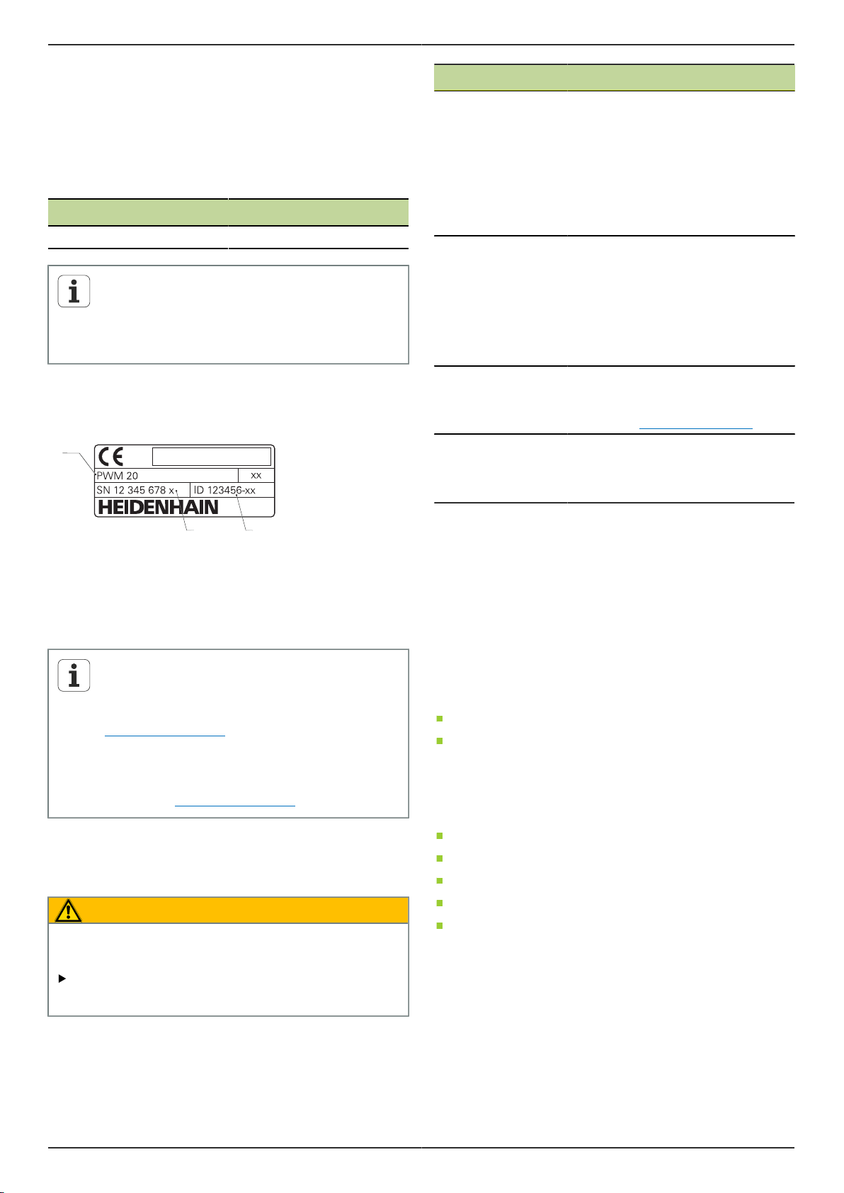
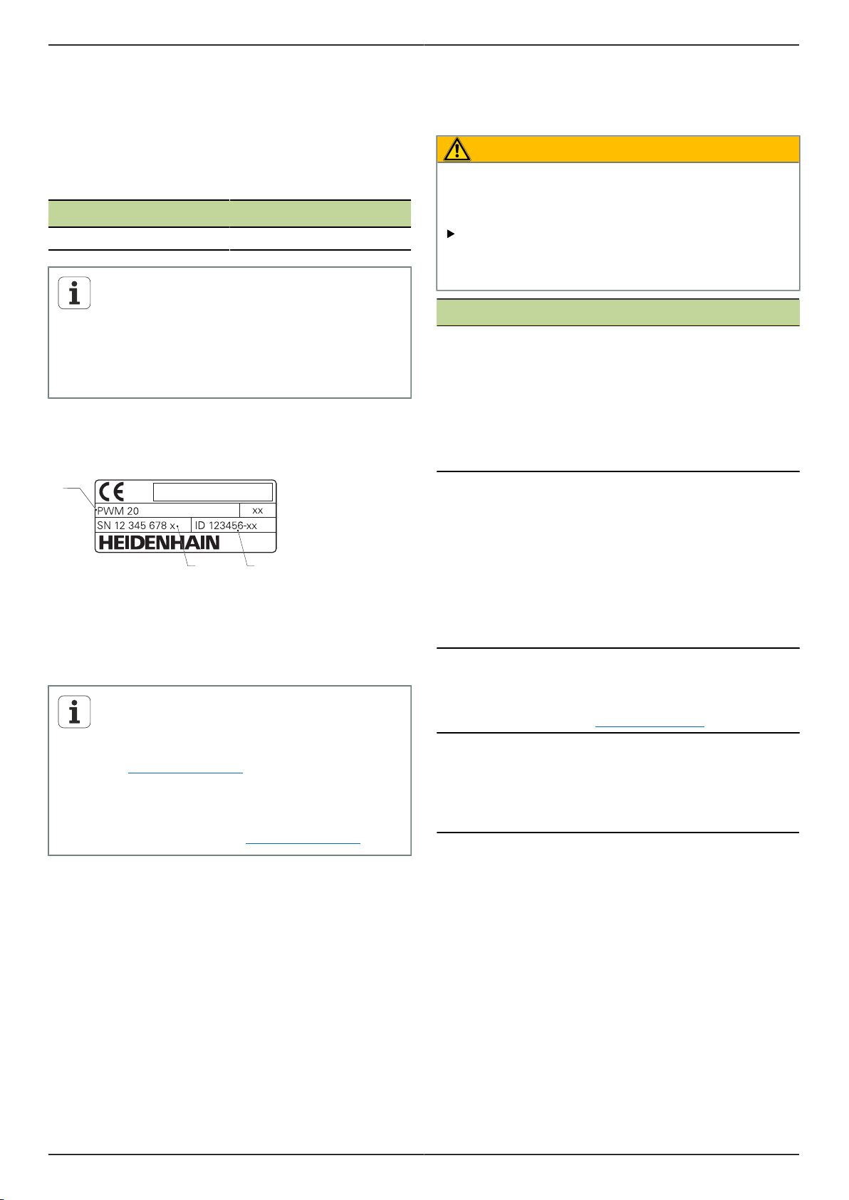
Typenschild
Das Typenschild befindet sich auf der Geräterückseite.
Beispiel:
Dokumentation Beschreibung
Addendum Ein Addendum ergänzt oder ersetzt
die entsprechenden Inhalte der Betriebsanleitung und ggf. auch der
Installationsanleitung. Wenn dieses Dokument in der Lieferung enthalten ist, muss es zuerst gelesen
werden. Alle übrigen Inhalte der
Dokumentation behalten ihre Gültigkeit.
Betriebsanleitung Die Betriebsanleitung enthält alle In-
formationen und Sicherheitshinweise, um das Gerät sachgerecht und
bestimmungsgemäß zu montieren,
installieren und zu betreiben. Sie ist
im Lieferumfang enthalten und hat
die zweithöchste Priorität beim Lesen.
Bedienungsanleitung ATS-Software
Dokumentation der
angeschlossenen
Messgeräte sowie
der sonstigen Peripherie
Die Dokumentation für die Bedienung des Geräts mit der ATS-Software kann im Downloadbereich von
www.heidenhain.de heruntergela-
den werden.
Diese Dokumente sind nicht in der
Lieferung enthalten. Sie sind Bestandteil der entsprechenden Lieferungen der Mess- und Peripheriegeräte
1
Produktbezeichnung
2
Teilenummer
3
Index
Gültigkeit der Dokumentation
Auf der letzten Seite der Dokumentation
steht unten links eine Dokumentnummer.
Die Dokumentation ist gültig, wenn die
Dokumentnummer mit der entsprechenden
Dokumentnummer unter www.heidenhain.de
übereinstimmt.
Dazu müssen die Produktbezeichnung, die
Teilenummer und der Index auf dem Typenschild
mit den entsprechenden Angaben unter
www.heidenhain.de verglichen werden.
1.2 Hinweise zum Lesen der Dokumentation
Die folgende Tabelle enthält die Bestandteile der
Dokumentation in der Reihenfolge ihrer Priorität beim
Lesen.
WARNUNG
Jede Nichtbeachtung kann Unfälle mit tödlichem
Ausgang, Verletzungen oder Sachschäden zur Folge
haben.
1.3 Aufbewahrung und Weitergabe der Dokumentation
Diese Anleitung muss in unmittelbarer Nähe des
Arbeitsplatzes aufbewahrt werden und dem gesamten
Personal jederzeit zur Verfügung stehen. Der Betreiber
muss das Personal über den Aufbewahrungsort dieser
Anleitung informieren. Wenn die Anleitung unleserlich
geworden ist, dann muss durch den Betreiber Ersatz beim
Hersteller beschafft werden.
Bei Übergabe oder Weiterverkauf des Geräts an Dritte
müssen die folgenden Dokumente an den neuen Besitzer
weitergegeben werden:
Addendum, falls mitgeliefert
Betriebsanleitung
1.4 Zielgruppe der Anleitung
Die Betriebsanleitung muss von jeder Person gelesen und
beachtet werden, die mit einer der folgenden Arbeiten
betraut ist:
Montage
Installation
Bedienung
Wartung
Demontage, Umweltschutz und Entsorgung
Dokumentation sorgfältig und vollständig lesen und
aufbewahren zum Nachschlagen.
5
Page 4

Betriebsanleitung de PWM 20
2 Sicherheit
Für den Betrieb des Systems gelten die allgemein
anerkannten Sicherheitsvorkehrungen wie sie insbesondere
beim Umgang mit stromführenden Geräten erforderlich
sind. Nichtbeachtung dieser Sicherheitsvorkehrungen kann
Schäden am Gerät oder Verletzungen zur Folge haben.
Die Sicherheitsvorschriften können je nach Unternehmen
variieren. Im Falle eines Konflikts zwischen dem Inhalt
dieser Anleitung und den internen Regelungen eines
Unternehmens, in dem dieses Gerät verwendet wird, gelten
die strengeren Regelungen.
2.1 Bestimmungsgemäße Verwendung
Das Gerät darf nur in einem einwandfreiem und sicheren
Zustand betrieben werden. Es ist ausschließlich für die
folgende Verwendung bestimmt:
Diagnose und Justage von HEIDENHAIN-Messgeräten
mit absoluten und inkrementalen Schnittstellen
Eine andere oder darüber hinausgehende Benutzung des
Geräts gilt als nicht bestimmungsgemäß und kann zu
Gefahren und Schäden führen.
2.2 Bestimmungswidrige Verwendung
Jede Verwendung, die nicht in "Bestimmungsgemäße
Verwendung" genannt ist, gilt als nicht bestimmungsgemäß.
Für hieraus resultierende Schäden haftet allein der Betreiber
des Geräts.
Zusätzlich gelten die folgenden Verwendungen als nicht
zulässig:
Verwendung mit defekten oder nicht normgerechten
Teilen, Kabeln oder Anschlüssen
Verwendung in explosions- oder feuergefährlicher
Umgebung
Verwendung jenseits der Betriebsbedingungen gemäß
"Technische Daten"
Veränderungen am Gerät oder an der Peripherie ohne
Zustimmung der Hersteller
2.3 Qualifikation des Personals
Für Montage, Installation, Bedienung, Wartung und
Demontage ist eine Fachqualifikation als Servicetechniker
erforderlich. Der Servicetechniker muss sich für die Arbeiten
mit dem Gerät mithilfe der Dokumentation des Geräts und
der angeschlossenen Peripherie ausreichend informiert
haben.
Nachfolgend sind die Qualifikationen spezifiziert:
Der Servicetechniker nutzt und bedient das Gerät im
Rahmen der bestimmungsgemäßen Verwendung. Er ist
speziell für das Arbeitsumfeld ausgebildet, in dem er tätig
ist. Der Servicetechniker ist aufgrund seiner fachlichen
Ausbildung, Kenntnisse und Erfahrung sowie Kenntnis
der einschlägigen Normen und Bestimmungen in der
Lage, die ihm übertragenen Arbeiten hinsichtlich der
jeweiligen Applikation auszuführen und mögliche Gefahren
selbstständig zu erkennen und zu vermeiden. Er muss die
Bestimmungen der geltenden gesetzlichen Vorschriften zur
Unfallverhütung erfüllen.
2.4 Betreiberpflichten
Der Betreiber besitzt das Gerät und die Peripherie
oder hat beides gemietet. Er ist jederzeit für die
bestimmungsgemäße Verwendung verantwortlich.
Der Betreiber muss:
die verschiedenen Aufgaben am Gerät qualifiziertem,
geeignetem und autorisiertem Personal zuweisen
das Personal nachweisbar in die Befugnisse und
Aufgaben nach "Qualifikation des Personals" unterweisen
sicherstellen, dass das Gerät ausschließlich in technisch
einwandfreiem Zustand betrieben wird
sicherstellen, dass das Gerät gegen unbefugte
Benutzung geschützt wird
6
Page 5
PWM 20 Betriebsanleitung de
2.5 Allgemeine Sicherheitshinweise
Die spezifischen Sicherheitshinweise, die für die einzelnen
Tätigkeiten am Gerät zu beachten sind, sind in den
entsprechenden Kapiteln dieser Anleitung angegeben.
2.5.1 Klassifizierung der Warnhinweise
Warnhinweise warnen vor Gefahren im Umgang mit dem
Gerät und geben Hinweise zu deren Vermeidung. Sie
sind nach der Schwere der Gefahr klassifiziert und in die
folgenden Gruppen unterteilt:
Hinweisarten
GEFAHR
Bezeichnet eine unmittelbar drohende Gefahr.
Wenn sie nicht gemieden wird, sind Tod oder schwerste
Verletzungen unmittelbar die Folge.
WARNUNG
Bezeichnet eine möglicherweise drohende Gefahr.
Wenn sie nicht gemieden wird, können Tod oder
schwerste Verletzungen die Folge sein.
VORSICHT
Bezeichnet eine möglicherweise drohende Gefahr.
Wenn sie nicht gemieden wird, können leichte oder
geringfügige Verletzungen die Folge sein.
ACHTUNG
Bezeichnet eine möglicherweise schädliche Situation.
Wenn sie nicht gemieden wird, kann das Gerät oder
etwas in seiner Umgebung beschädigt werden.
Ein Informationskasten gibt wichtige
zusätzliche oder ergänzende Informationen
über eine Aktivität oder ein Konzept.
Er macht auch auf Situationen oder Umstände
aufmerksam, die zu Messfehlern oder
Fehlfunktionen führen könnten.
2.5.2 Sicherheitshinweise zur Elektrik
GEFAHR
Beim Öffnen des Geräts kann es zum Kontakt mit
spannungsführenden Teilen kommen.
Elektrischer Schock, Verbrennungen oder der Tod können
die Folge sein. Außerdem erlischt durch das Öffnen
des Geräts die Garantie, die Gewährleistung sowie die
Haftung des Herstellers für daraus resultierende Unfälle,
Personen- und Sachschäden.
Auf keinen Fall das Gehäuse öffnen.
Eingriffe nur vom Hersteller vornehmen lassen.
GEFAHR
Bei direktem oder indirektem Kontakt mit
spannungsführenden Teilen kommt es zu einer
gefährlichen Körperdurchströmung.
Elektrischer Schock, Verbrennungen oder der Tod können
die Folge sein.
Arbeiten an der Elektrik und an stromführenden
Bauteilen nur durch eine ausgebildete Fachkraft
durchführen lassen.
Für Netzanschluss und alle Schnittstellenanschlüsse
ausschließlich normgerecht gefertigte Kabel und
Stecker verwenden.
Betauung verhindern.
Gerät bei Beschädigung nicht reparieren und nicht
mehr betreiben
Defekte elektrische Bauteile sofort über den
Hersteller austauschen lassen.
Alle angeschlossenen Kabel und Anschlussbuchsen
des Geräts regelmäßig prüfen. Mängel, z.B. lose
Verbindungen bzw. angeschmorte Kabel, sofort
beseitigen.
ACHTUNG
Dieses Produkt enthält Bauteile,
die durch elektrostatische Entladung (ESD) zerstört werden können.
Sicherheitsvorkehrungen für die
Handhabung ESD-empfindlicher
Bauteile unbedingt beachten.
Anschlussstifte niemals ohne ordnungsgemäße Erdung berühren.
7
Page 6
Betriebsanleitung de PWM 20
2.6 Sicherheitsmaßnahmen beim Betrieb mit und in Maschinen
WARNUNG
Gefahr von erheblichen Personen- und Sachschäden
durch unsachgemäßen Gebrauch.
Eine Fehlbedienung der NC, eine falsche NCProgrammierung, falsche bzw. nicht optimierte
Maschinenparameterwerte können zu einem
Fehlverhalten der NC-gesteuerten Maschine führen.
Um das Fehlverhalten einer NC-gesteuerten
Maschine richtig beurteilen zu können, müssen
grundlegende Kenntnisse über Maschine,
Antriebe, Umrichter und NCs, sowie über deren
Zusammenwirken mit den Messgeräten vorhanden
sein.
Neben den Hinweisen dieser Anleitung
müssen daher die besonderen Sicherheits- und
Unfallverhütungsvorschriften im Umgang mit den
jeweiligen Maschinen, Antrieben, Umrichtern und
NCs Berücksichtigung finden!
Beim Einbau des Geräts in eine Maschine
oder bei anderen speziellen Anwendungsfällen
müssen alle in dieser Anleitung aufgeführten
Sicherheitsmaßnahmen auf die Besonderheiten der
jeweiligen Verwendungssituation angepasst werden!
Insbesondere die erforderlichen Anpassungen
an geänderte Erdungssituationen bei Einbau und
Einschleifbetrieb in den Regelkreis NC-gesteuerter
Maschinen müssen befolgt werden.
Bei der Fehlerdiagnose ist unbedingt der
Maschinenhersteller zu Rate zu ziehen.
3 Montage
3.1 Lieferumfang
In der Lieferung der Grundausstattung sind folgende Artikel
enthalten:
Gerät
3 m langes Netzkabel mit Euro-Netzstecker
Betriebsanleitung
2 m langes USB-Anschlusskabel
CD mit ATS-Software
Addendum (optional, weitere Informationen siehe
"Hinweise zum Lesen der Dokumentation", Seite 5)
Das Gerät kann optional als Bestandteil
eines Messgerät-Diagnosesets geliefert
werden. In diesem Fall besteht die Lieferung
aus zusätzlichen Bestandteilen. Weitere
Informationen siehe Bedienungsanleitung ATSSoftware.
Gerät auspacken
Verpackungskarton oben öffnen.
Verpackungsmaterial entfernen.
Inhalt entnehmen.
Lieferung auf Vollständigkeit prüfen.
Lieferung auf Transportschäden kontrollieren.
Bei einem Transportschaden die
Verpackungsmaterialien zur Untersuchung
aufbewahren und den HEIDENHAIN-Händler
oder Gerätehersteller kontaktieren. Dies gilt auch
für Ersatzteilanforderungen.
Wenn ein Transportschaden vorliegt
Schaden vom Spediteur bestätigen lassen.
Verpackungsmaterialien zur Untersuchung aufheben.
Absender über den Schaden benachrichtigen.
Gegebenenfalls an den Händler als Vermittler wenden.
HEIDENHAIN-Händler oder Gerätehersteller bezüglich
Ersatzteilen kontaktieren.
Zubehör
Eine Übersicht optionaler Artikel, die bei HEIDENHAIN
für dieses Gerät bestellt werden können, ist in der
Bedienungsanleitung ATS-Software enthalten.
8
Page 7
PWM 20 Betriebsanleitung de
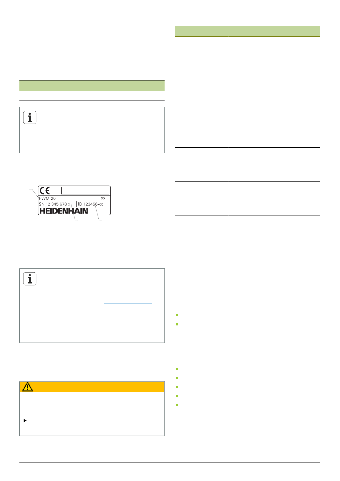
3.2 Aufstellort
ACHTUNG
Schäden am Gerät durch falsche Aufstellung.
Gerät nur horizontal aufstellen.
Aufstellort so wählen, dass das Gerät während des
Betriebs leicht zugänglich ist.
Auf gute Durchlüftung achten.
Hintere und seitliche Lüftungsöffnungen frei halten
und Luftströmung nicht behindern.
Das Gerät verfügt über einen
temperaturgesteuerten Lüfter, der
bei Überschreitung einer maximalen
Innentemperatur einschaltet und nach Abkühlung
wieder ausschaltet.
Informationen zur Einbaulage siehe "C" auf der
ausklappbaren Umschlagseite.
4 Installation
ACHTUNG
Gefahr der Beschädigung von internen Bauteilen!
Steckverbindungen nur bei ausgeschaltetem Gerät
herstellen oder lösen.
Je nach Ausstattungsvariante kann die
Installation von dem in diesem Kapitel
beschriebenen Vorgehen abweichen. Falls
das mit dem Produkt mitgelieferte Addendum
Informationen zur Installation enthält, dann
haben die dort beschriebenen Informationen
Vorrang vor dem in diesem Kapitel enthaltenen
Informationen.
In den Abbildungen von Pin-Belegungen sind
durchgehend die Belegungen der Anschlüsse am
Gerät und nicht der Stecker dargestellt.
Die Verantwortung für jedes System, in dem
das Gerät verwendet wird, liegt beim Betreiber
dieses Systems.
9
Page 8
Betriebsanleitung de PWM 20
4.1 Geräteübersicht
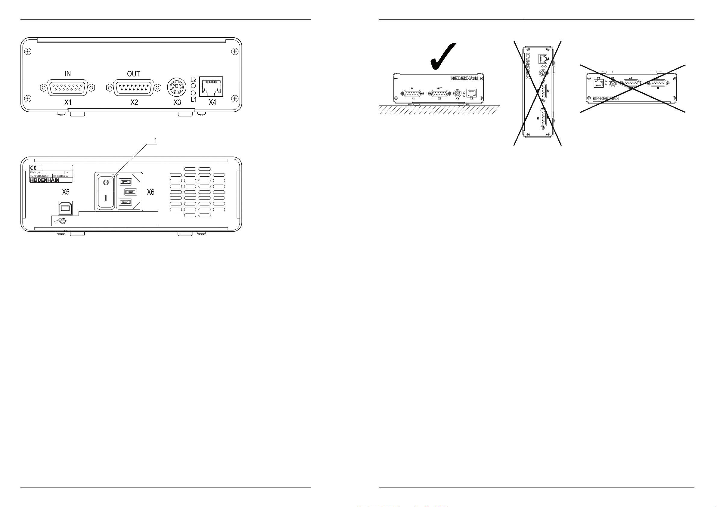
Gerätevorderseite
Siehe "A" auf der ausklappbaren Umschlagseite.
X1
X2
X3
X4
L1
L2
Geräterückseite
Siehe "B" auf der ausklappbaren Umschlagseite.
1
X5
X6
15-poliger Sub-D-Eingang für HEIDENHAINMessgeräte mit
11 µASS/25 µASS-Schnittstelle
1 VSS/3 VSS-Schnittstelle
(1 VSS/Z1, 1 VSS mit Grenzlagen,
1 VSS mit Takt/Daten)
EnDat/SSI-Schnittstelle
TTL-Schnittstelle mit Grenzlagen
HTL-Schnittstelle (Anschluss nur für
Servicezwecke über externen Adapter,
z.B. ID 1093210-01)
Fanuc-, Mitsubishi-, Yaskawa- oder Panasonic-Schnittstelle
15-poliger Sub-D-Ausgang für den Durchschleifbetrieb der Messgerätsignale aus X1
6-poliger Mini-DIN-Anschluss für externe
Funktionen
8+2-poliger RJ-45-Anschluss für Messgeräte mit DRIVE-CLiQ-Schnittstelle
Statusanzeige für Betriebsbereitschaft
Aus: Nicht betriebsbereit
Ein (grün): Betriebsbereit
Statusanzeige für Messgeräteversorgung
Aus: Messgeräteversorgung ausgeschaltet
Ein (grün): Messgeräteversorgung eingeschaltet
Netzschalter
USB-Buchse Typ B (USB 2.0), Datenschnittstelle
Netzanschluss
4.2 Netzspannung anschließen
WARNUNG
Stromschlaggefahr!
Nicht ordnungsgemäß geerdete Geräte können zu
ernsthaften Verletzungen oder Tod durch Stromschlag
führen.
Grundsätzlich 3-poliges Netzkabel verwenden.
Korrekten Schutzleiteranschluss an die
Gebäudeinstallation sicherstellen.
WARNUNG
Brandgefahr durch Verwendung von Netzkabeln, die die
Mindestanforderungen nicht erfüllen!
Grundsätzlich Netzkabel verwenden, das die
aufgeführten Mindestanforderungen erfüllt oder
übersteigt.
Netzanschluss X6 mit dem mitgelieferten Netzkabel an
Netzsteckdose mit Schutzleiter anschließen.
Informationen zur Lage des Netzanschlusses an der
Geräterückseite siehe "Geräterückseite", Seite 10.
Signalbelegung des Netzanschlusses X6 siehe "R".
4.3 Elektrostatische Entladung
ACHTUNG
Dieses Produkt enthält Bauteile,
die durch elektrostatische Entladung (ESD) zerstört werden können.
Sicherheitsvorkehrungen für die
Handhabung ESD-empfindlicher
Bauteile unbedingt beachten.
Anschlussstifte niemals ohne ordnungsgemäße Erdung berühren.
10
Page 9
PWM 20 Betriebsanleitung de
4.4 Messgeräte anschließen
ACHTUNG
Gefahr von Geräteschaden und Messgeräteschaden
durch falschen Spannungsversorgungsbereich und
falsche Verdrahtung!
Spannungsversorgungsbereich des angeschlossenen
Messgeräts beachten.
Prüfen, ob das Verbindungskabel zwischen Messgerät
und Gerät korrekt verdrahtet ist.
Verbindungskabel zwischen Messgerät und Gerät
nur im spannungsfreien Zustand anstecken bzw.
abziehen.
Für den Anschluss und Betrieb des Geräts mit
Messgeräten, die nicht von HEIDENHAIN stammen,
trägt der Anwender jegliches Risiko.
Anschlussmöglichkeiten
Messgeräte mit einer 15-poligen Schnittstelle werden an
den Messgeräte-Eingang X1 auf der Gerätevorderseite
angeschlossen
Im Einschleifbetrieb wird für Messgeräte mit einer
15-poligen Schnittstelle der Messgeräte-Ausgang X2
verwendet
Messgeräte mit 8+2-poligen DRIVE-CLiQ-Schnittstellen
werden an den Messgeräte-Eingang X4 auf der
Gerätevorderseite angeschlossen
Informationen zur Lage der Anschlüsse siehe
"Geräteübersicht", Seite 10.
Die Anschlussbelegungen der Verbindungskabel sind dem
Katalog zu entnehmen.
Hinweise zur Signalbelegung der Pins im
Anhang:
Kabelschirm mit Gehäuse verbunden;
UP = Spannungsversorgung
Sensor: Die Sensorleitungen sind abhängig von
den Einstellungen in der ATS-Software intern mit
der jeweiligen Spannungsversorgung verbunden
(Dokument "Bedienungsanleitung ATS-Software",
siehe "Hinweise zum Lesen der Dokumentation",
Seite 5).
EnDat/SSI-Schnittstelle
Pin Funktion
1, 3, 7, 9, 11, 14 Inkrementalsignale (nur bei Bestellbe-
zeichnung EnDat 01 und EnDat 02)
2, 4, 10, 12 Spannungsversorgung
5, 8, 13, 15 Positionswerte
6 Innenschirm
Signalbelegung EnDat/SSI siehe "F".
Fanuc-, Mitsubishi-, Yaskawa-, PanasonicSchnittstelle
Pin Funktion
1, 3, 7, 9, 11, 14 Inkrementalsignale (wenn vorhanden,
nur für Abgleichzwecke; im Normalbe-
trieb nicht belegen)
2, 4, 10, 12 Spannungsversorgung
5, 8, 13, 15 Positionswerte
6 /
Signalbelegung Fanuc siehe "G".
Signalbelegung Mitsubishi siehe "H".
Signalbelegung Yaskawa und Panasonic siehe "I".
Fanuc und Mitsubishi: Pins 5 und 13 nicht
belegen bei „one pair transmission“.
1 VSS-/3 VSS-Schnittstelle
Pin Funktion
1, 3, 7, 9, 11, 14 Inkrementalsignale
2, 4, 10, 12 Spannungsversorgung
5, 6, 8, 13, 15 weitere geräteabhängige Signale
(Geräte-interne Umschaltung)
Signalbelegung 1 VSS mit Grenzlagen siehe "J".
Signalbelegung 1 VSS/Z1 siehe "K".
Signalbelegung 1 VSS mit Takt/Daten siehe "L".
11 µASS/25 µASS-Schnittstelle
Pin Funktion
1, 3, 7, 9, 11, 14 Inkrementalsignale
2, 4 Spannungsversorgung
5, 6, 8, 10, 12, 13, 15 /
6 Innenschirm
Signalbelegung 11 µASS (25 µASS) siehe "M".
11
Page 10

Betriebsanleitung de PWM 20
TTL- (mit Grenzlagen) und HTL-Schnittstelle
Pin Funktion
1, 3, 7, 9, 11, 14 Inkrementalsignale
2, 4, 10, 12 Spannungsversorgung
3, 13, 15 /
6, 8 Limit-Signale
(wenn vom Messgerät unterstützt)
Signalbelegung TTL und HTL siehe "N".
Anschluss X4
Signalbelegung DRIVE-CLiQ siehe "P".
Messgeräte-Ausgang X2
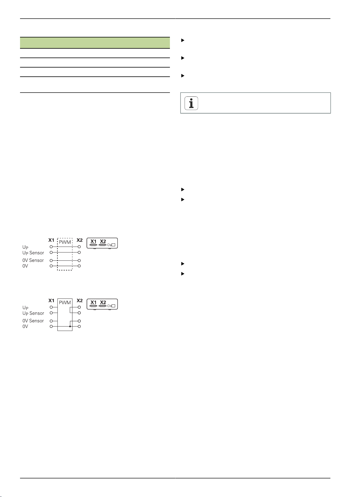
Der Messgeräte-Eingang X1 des Geräts ist mit dem
Messgeräte-Ausgang X2 galvanisch verbunden. Die
Signale bzw. die Pin-Belegung am Ausgang entsprechen
den jeweiligen Signalen am Eingang (Abgriff oder aktiv
nachgebildet).
Es erfolgt keine galvanische Trennung der Signale. Die
Versorgungs- und Sensorleitungen werden in Abhängigkeit
von der jeweiligen Betriebsart durch die ATS-Software
ab V2.6 geschaltet und können verbunden sein (siehe
nachfolgende Beispiele). Es ist immer sichergestellt, dass
die vom Gerät erzeugte Versorgungsspannung nicht an X2
anliegt.
Beispiel 1 – Gerät im Durchschleifbetrieb (Messgerät wird
von Folge-Elektronik versorgt) bzw. ATS-Software nicht
gestartet:
Kabel der Messgeräte anschließen
Messgeräte fest an den jeweiligen Anschlüssen
anschließen.
Bei Steckern mit Schrauben: Schrauben nicht zu fest
anziehen.
Auf Steckverbindungen (Messgeräte-Eingang X4) keine
mechanische Belastung ausüben.
Nicht verwendete Pins oder Litzen dürfen nicht
belegt werden.
4.4.1 Erdungsverhältnisse beim Einschleifbetrieb
Das Gerät verfügt über ein internes
Weitbereichsschaltnetzteil. Deshalb ist der
Schutzleiteranschluss PE (Schutzerde) notwendig,
der auch mit dem Gehäuse des Geräts verbunden ist.
Wird das Gerät in den Regelkreis einer NC-gesteuerten
Maschine eingebunden, dann stellt es einen zusätzlichen
Erdungspunkt dar, der das Schirmkonzept verändert.
Das lässt sich mit folgenden Maßnahmen verhindern:
Gerät über einen Trenntrafo versorgen, oder
Gerät mit DC 24 V versorgen
Zur Auswertung von Messdaten des Geräts
wird ein PC an die USB-Schnittstelle des Geräts
angeschlossen. Üblicherweise sind im PC die 0 V und der
Schutzleiteranschluss miteinander verbunden (auch USB).
Wird das Gerät in den Regelkreis einer NC-gesteuerten
Maschine eingebunden, dann verändern sich auch die
Verhältnisse auf der 0-V-Verbindung.
Das lässt sich mit folgenden Maßnahmen verhindern:
Beispiel 2 – Gerät versorgt das Messgerät über X1:
Als PC einen batteriebetriebenen Laptop verwenden,
oder
Laptop mit einem Netzteil ohne Schutzleiteranschluss
verwenden
12
Page 11
PWM 20 Betriebsanleitung de
4.4.2 Einschleifen in den Regelkreis einer NCgesteuerten Maschine
Das Gerät kann über den Messgeräte-Eingang und Ausgang für Diagnosezwecke in den Regelkreis einer
NC-gesteuerten Maschine eingebunden werden (siehe
"Messgeräte-Ausgang X2", Seite 12).
WARNUNG
Stromschlaggefahr!
Beim Einbau des Geräts in den Regelkreis einer
NC-gesteuerten Maschine können sich die
Erdungsverhältnisse ändern.
Erdung und die Besonderheiten der
Verwendungssituation anpassen.
Abhängig von der Version der ATS-Software kann unter
Beachtung der Hinweise zu den Erdungsverhältnissen der
Betrieb des Geräts im geschlossenen Regelkreis erfolgen.
Grundsätzlich ist jedoch die Verwendung eines
Signaladapters (z. B. SA 100, SA 110, …) erforderlich bzw.
empfohlen.
Gerät in der folgenden Reihenfolge anschließen
Zuerst Maschine ausschalten.
Dann Steckverbindungen lösen.
5 Bedienung
WARNUNG
Gefahr von Maschinen- oder Personenschäden bei
Änderungen an Messgeräte-Spannungen im laufenden
Betrieb und bei ungesicherten Vertikal-Achsen.
Keine Parameter bzw. Messgeräte-Spannungen am
Gerät verändern, während die Maschine verfährt und
sich im Regelkreis ein PWM befindet.
Vertikal-Achsen grundsätzlich vor Herabfallen sichern,
bevor Messungen an diesen Achsen vorgenommen
werden.
VORSICHT
Gefahr von Maschinen- oder Personenschäden bei nicht
angeglichenen Speicherbereichen.
Einige Schnittstellen, z.B. EnDat, bieten die Möglichkeit
im Speicherbereich des Kunden maschinen- oder
anlagenspezifische Daten zu hinterlegen. Diese Daten
können sicherheitsrelevante Informationen beinhalten.
Im Servicefall darauf achten, dass Speicherbereiche
mit maschinen- oder anlagenspezifische Daten
angeglichen werden.
4.5 Computer anschließen
An den USB-Anschluss X5 (USB Typ B) kann ein
Computer über dessen USB-2.0-High-Speed-Schnittstelle
angeschlossen werden.
USB-Port des Computers mithilfe eines USB-Kabels
(siehe "Lieferumfang", Seite 8) an den Anschluss X5
anschließen.
Informationen zur Lage der Anschlüsse siehe
"Geräterückseite", Seite 10.
Anschlussbelegung X5 siehe "Q".
4.6 Externes Gerät anschließen
An den Anschluss X3 kann ein externes Gerät mit 6-poligem
Mini-DIN-Anschluss angeschlossen werden.
Mini-DIN-Anschluss des externen Geräts mithilfe eines
handelsüblichen Kabels mit 6-poligem Mini-DIN-Stecker
an den Anschluss X3 anschließen.
Informationen zur Lage der Anschlüsse siehe
"Gerätevorderseite", Seite 10.
Anschlussbelegung X3 siehe "O".
5.1 Gerät ein- und ausschalten
Gerät einschalten
Informationen zur Lage des Netzschalters siehe
"Geräterückseite", Seite 10.
Netzschalter auf Position I stellen.
Gerät ausschalten
Netzschalter auf Position 0 stellen.
Der Netzschalter ist allpolig abgesichert.
Das Gerät kann nur durch Ziehen des
Netzsteckers endgültig von der Stromquelle
getrennt werden.
13
Page 12
Betriebsanleitung de PWM 20
5.2 Status- und Fehleranzeigen
Die Betriebszustände des Geräts sind an den LEDs L1 und
L2 auf der Gerätevorderseite ersichtlich.
Informationen zur Lage der LEDs siehe "Gerätevorderseite",
Seite 10.
LED Zustand Status
L1 Aus
Ein (grün)
L2 Aus
Ein (grün)
Nicht betriebsbereit
Betriebsbereit
Messgeräteversorgung ausgeschaltet
Messgeräteversorgung eingeschaltet
5.3 ATS-Software
Das PWM 20 dient zur detaillierten Überprüfung eines
inkrementalen bzw. absoluten Messgeräts (abhängig von
der Schnittstelle auch im geschlossenen Regelkreis).
Zur Bedienung kann die mitgelieferte ATS-Software am
PC installiert werden. Die Installation und Bedienung der
ATS-Software ist im Dokument "ATS-Bedienungsanleitung"
beschrieben, siehe "Hinweise zum Lesen der
Dokumentation", Seite 5.
Empfohlene Systemvoraussetzungen
IBM-PC oder 100 % kompatibler PC
Bildschirmauflösung für ATS-Software: ab 1024 x 768
Windows Vista, Windows 7 (32 und 64 Bit) oder
Windows 8
200 MByte freier Speicher auf der Festplatte (bei
Verwendung der ATS-Software)
Arbeitsspeicher > 2 GByte
USB 2.0 High Speed
6 Wartung
Dieses Kapitel enthält nur die Beschreibung
der Wartungsarbeiten des Geräts. Zur
Beschreibung von Wartungsarbeiten, die die
Peripheriegeräte betreffen, siehe Dokumentation
der entsprechenden Peripheriegeräte.
6.1 Reinigung
ACHTUNG
Keine scheuernden oder aggressiven
Reinigungsmittel oder Lösungsmittel verwenden.
Kein triefend nasses Tuch verwenden.
Außenflächen mit einem mit Wasser und einem milden
Reinigungsmittel befeuchteten Tuch abwischen.
6.2 Wartungsplan
Das Gerät arbeitet weitgehend wartungsfrei.
ACHTUNG
Gerät bei Beschädigung nicht reparieren und nicht
mehr betreiben.
Defekte elektrische Bauteile sofort über den
Hersteller austauschen lassen.
Jährliche Wartungsschritte
Alle Kennzeichnungen,
Beschriftungen und Symbole auf dem Gerät auf
Lesbarkeit prüfen
Elektrische Verbindungen
auf Beschädigungen und
Funktion prüfen
Netzanschlussleitung auf
fehlerhafte Isolation oder
Schwachstellen prüfen
Schutzleiteranschluss auf
festen Sitz und Funktion
prüfen
Fehlerbehebung
HEIDENHAIN Serviceniederlassung kontaktieren
Fehlerhafte Leitungen austauschen lassen, HEIDENHAIN
Serviceniederlassung kontaktieren
Netzanschlussleitung entsprechend der Spezifikation
ersetzen
Anschlussleitungen erneuern
lassen
14
Um einen rückführbaren, genauen und
fehlerfreien Betrieb garantieren zu können,
wird empfohlen, das Gerät alle 2 Jahre an den
Kalibrierdienst von HEIDENHAIN einzusenden.
Page 13
PWM 20 Betriebsanleitung de
7 Demontage, Umweltschutz und
Entsorgung
Bei der Demontage aus NC-gesteuerten
Maschinen müssen ggf. besondere
Sicherheitsmaßnahmen beachtet
werden. Weitere Informationen siehe
"Sicherheitsmaßnahmen beim Betrieb mit und in
Maschinen", Seite 8.
Außerdem gelten die bei der Installation
beschriebenen Sicherheitshinweise, siehe
"Installation", Seite 9.
Vorbereitung
Netzschalter auf Position 0 stellen.
Netzstecker des Geräts ziehen.
Alle Anschlussverbindungen des Geräts trennen.
7.1 Demontage
Lagerung nach der Demontage
Soll das Gerät nach der Demontage zwischengelagert
werden, müssen die Bestimmungen für die
Umgebungsbedingungen eingehalten werden, siehe
"Technische Daten", Seite 16.
7.2 Umweltschutz und Entsorgung
ACHTUNG
Falsche Entsorgung des Geräts, Zubehörs oder von
Peripheriegeräten!
Umweltschäden können die Folge sein!
Nicht im Hausmüll entsorgen!
Elektroschrott und Elektronikkomponenten
unterliegen der Sondermüllbehandlung und dürfen
nur von autorisierten Annahmestellen entsorgt
werden.
Es sind die Vorschriften des jeweiligen Landes zu
beachten.
Genaue Informationen zu gesetzlichen Regelungen
gibt die zuständige Verwaltungsbehörde (z. B.
Wasserwirtschafts- und Umweltämter auf Bundesund Landesebene).
Bei offenen Fragen zur Entsorgung an die
Hersteller wenden!
Gerät verpacken
Die Wiederverpackung sollte der Originalverpackung so gut
wie möglich entsprechen:
Alle Verschraubungsteile am Gerät anbringen, wie sie bei
der Lieferung des Geräts angebracht waren oder diese
zurückpacken, wie sie verpackt waren.
Gerät in die Kartoneinsätze gemäß dem originalen
Lieferzustand verpacken.
Alle weitere Bestandteile wie erhalten in die
Originalverpackung legen, siehe "Lieferumfang", Seite 8.
Sämtliche im Lieferzustand beigepackten
Dokumentationen beilegen, siehe "Aufbewahrung und
Weitergabe der Dokumentation", Seite 5.
Bei Rücksendung des Geräts zum Kundendienst
müssen Zubehör sowie Messgeräte nicht mit
dem Gerät zurück geschickt werden.
15
Page 14
Betriebsanleitung de PWM 20
8 Technische Daten
Elektrische Daten
Spannungsversorgung
Messung von
Versorgungsspannung und
-strom
Messgeräte-Eingang X1
15-poliger Sub-D-Anschluss, Buchse
Unterstützung abhängig von Software-Version der ATSSoftware
Einstellbar 2 V bis 30 V mit/ohne remote sense Regelung
Strombegrenzung 750 mA
Hinweis zu den Kabellängen:
Bei Verwendung von HEIDENHAIN-Kabeln.
Der Versorgungsspannungsbereich des
Messgeräts muss eingehalten werden.
EnDat 2.1/
SS
1
1
EnDat 2.2
1 V
AC 100 V bis 240 V (±10 %),
50 Hz bis 60 Hz (±2 Hz)
ca. 20 W
DC 24 V (±10 %),
ca. 20 W
Spannung: ±0,5 % (min. ±5 mV)
Strom: ±2 % (min. ±1 mA)
Kabellänge: Funktionsgrenze < 100 m,
abhängig von Taktfrequenz
Einhaltung Prüfgrenzen < 2 m
(nur Inkrementalsignale)
Eingangsfrequenz Inkrementalsignale3:
< 1000 kHz
Kabellänge: Funktionsgrenze < 150 m
Einhaltung Prüfgrenzen < 2 m
Eingangsfrequenz Inkrementalsignale2:
< 1000 kHz
Messgeräte-Eingang X1
1
11 µA
ss
Kabellänge: Funktionsgrenze < 30 m
Einhaltung Prüfgrenzen < 2 m
Eingangsfrequenz Inkrementalsignale2:
< 300 kHz
Fanuc,
Mitsubishi,
Kabellänge: Funktionsgrenze < 30 m
Yaskawa
Panasonic
SSI
1
Inkrementalsignale werden invertiert dargestellt
2
Grenzfrequenz, von der ATS-Software für bestimmte
Messfunktionen auf 100 kHz reduziert
3
wenn vom angeschlossenen Messgerät unterstützt
4
HTL nur für Servicezwecke über externen Signaladapter,
z.B. ID 1093210-01
Kabellänge: Funktionsgrenze < 100 m
Messgeräte-Ausgang X2
15-poliger Sub-D-Anschluss, Stifte
Durchschleif-
betrieb von X1
direkt oder über Signaladapter SA xxx,
abhängig von der ATS-Version für
EnDat 2.1/EnDat 2.2
Fanuc/Mitsubishi
1 V
ss
TTL
11 µA
ss
Externe Funktionen X3
6-poliger Mini-DIN-Anschluss, Buchse
MSB-Ausgabe Für EnDat 2.1/2.2
Messgeräte-Eingang X4
8+2-poliger RJ-45-Anschluss, Buchse
DRIVE-CLiQ
1
Nur für HEIDENHAIN-Messgeräte
TTL
HTL
16
Kabellänge: Funktionsgrenze
< 100 m/50 m, abhängig von min. Flankenabstand
Einhaltung Prüfgrenzen < 2 m
Eingangsfrequenz Inkrementalsignale:
1
DRIVE-CLiQ ist eine geschützte Marke der Siemens
Aktiengesellschaft, es werden nur HEIDENHAIN-Messgeräte
unterstützt
Daten-Schnittstelle X5
USB USB 2.0 High Speed
1
< 1000 kHz
1
Flankenabstand > 20 ns
4
Kabellänge: Funktionsgrenze < 300 m,
Niedrigere USB-Übertragungsgeschwindigkeiten können zu
Messfehlern führen.
abhängig von min. Flankenabstand
Einhaltung Prüfgrenzen < 2 m
Eingangsfrequenz Inkrementalsignale:
< 500 kHz
Flankenabstand > 20 ns
Page 15

PWM 20 Betriebsanleitung de
Prüfgrenzen 1 V
SS
Messbereich für alle Eingangsfrequenzen: 1,54 VSS.
Der erweiterte Messbereich 2 (9,6 VSS) weist erhöhte
Toleranzen auf. Der Messbereich 2 wird bei wenigen
bestimmten Messgeräten (mit z.B. 3 VSS-Schnittstelle)
automatisch von der ATS-Software eingestellt.
Eingangsfrequenz in kHz
Parameter
< 1 1 … 250 250 … 500
Signalgröße
(A, B, R)
±2 % ±3 % ±4 %
Symmetrieabweichung
±0,002 ±0,006
–
Signalgrößenverhältnis
±0,5 % ±0,5 %
–
Tastverhältnisabweichung
TV1 bzw. TV2
±0,5° ±1° ±1,5°
Phasenwinkelabweichung
±0,5° ±1° ±1,5°
Referenzimpulsbreite
±2°
– –
Referenzimpulslage
Prüfgrenzen 11 µA
±2°
SS
Messbereich für alle Eingangsfrequenzen: 15,4 µA
– –
SS
Der erweiterte Messbereich 2 (96 µASS) weist erhöhte
Toleranzen auf. Der Messbereich 2 wird bei wenigen
bestimmten Messgeräten (mit z.B. 25 µASS-Schnittstelle)
automatisch von der ATS-Software eingestellt.
Eingangsfrequenz in kHz
Parameter
Signalgröße (A, B, R) ±3 % ±5 %
Symmetrieabweichung ±0,006 ±0,006
Signalgrößenverhältnis ±2 % ±2 %
Tastverhältnisabweichung
TV1 bzw. TV2 ±1,5° ±1,5°
Phasenwinkelabweichung ±0,5° ±1,0°
Referenzimpulsbreite ±6,0°
Referenzimpulslage ±3,0°
< 1 1 … 300
–
–
Prüfgrenzen TTL
Messbereich für alle Eingangsfrequenzen: 5 V
Eingangsfrequenz in kHz
Parameter
Signalgröße
Low-Pegel
High-Pegel
< 100 100 … 500 500 … 1000
1
±0,05 V
±2 %
– –
Tastverhältnisabweichung
TV1 bzw. TV2
±0,5° ±1,5° ±2,5°
Phasenwinkelabweichung
±0,5° ±1,5° ±2,5°
Referenzimpulsbreite
±0,5° ±1,5° ±2,5°
Referenzimpulslage
1
Signalgröße (Ua1, Ua1, Ua2, Ua2, Ua0, Ua0, UaS)
±0,5° ±1,5° ±2,5°
Prüfgrenzen HTL
Messbereich für alle Eingangsfrequenzen: 10 V bis 30 V.
Eingangsfrequenz in kHz
Parameter
Signalgröße
Low-Pegel
High-Pegel
< 100 100 … 500
1
±0,1 V
±3 %
–
Tastverhältnisabweichung
TV1 bzw. TV2
±0,5° ±1,5°
Phasenwinkelabweichung
±1,5° ±4°
Referenzimpulsbreite
±1,5° ±2,5°
Referenzimpulslage
1
HTL nur für Servicezwecke über externen Signaladapter, ID
1093210-01
±1,5° ±2,5°
Umgebungsbedingungen
Arbeitstemperatur
Lagertemperatur
Max. Verschmutzungsgrad
Schutzart
EN 60529
0 °C bis 45 °C, keine Betauung
0 °C bis 70 °C, keine Betauung
II
IP 20
Anschlussmaße
Siehe Anschlussmaßzeichnungen "D".
Alle Maße sind in mm dargestellt.
17
Page 16
Operating Instructions en PWM 20
1
2
3
1 About these instructions
These instructions provide all the information and safety
precautions needed for the proper mounting and installation
of the product, as well as for operation of the unit as far as it
is used without the ATS software.
1.1 Information on the model
Product designation ID number
PWM 20 731626-01
The above-stated ID number is the number on
the ID label. The ID number on the packaging
label may differ from the number on the ID label
because the device can be delivered in different
packaging units.
ID label
The ID label is provided on the back of the product.
Example:
Documentation Description
Addendum An addendum supplements or su-
persedes the corresponding contents of the Operating Instructions
and, if applicable, of the Installation
Instructions. If this document is included in delivery, read it first before you proceed. All other contents
of the documentation retain their
validity.
Operating Instructions
Operating instructions for ATS software
Documentation of
connected measuring devices and
other peripherals
The Operating Instructions contain all the information and safety
precautions needed for the proper
mounting, installation and operation
of the product according to its intended use. It is included in delivery
and has the second highest priority
for reading.
The documentation on operating
the product with the ATS software
can be downloaded from the download area at www.heidenhain.de.
These documents are not included
in delivery. They are included with
the respective measuring devices
and peripherals
1
Product designation
2
ID number
3
Index
Validity of the documentation
A document number is provided at the bottom
left on the last page of the documentation. The
documentation is valid if the document number
matches the document number indicated at
www.heidenhain.de.
You therefore need to compare the product
designation, the ID number and the index given
on the ID label with the corresponding details
provided at www.heidenhain.de
1.2 Notes on reading the documentation
The table below lists the components of the documentation
in the order of priority for reading.
WARNING
Failure to comply with the documentation may result in
fatal accidents, personal injury or damage to equipment.
1.3 Storage and distribution of the documentation
These instructions must be kept in the immediate vicinity of
the workplace and must be available to all personnel at all
times. The operating company must inform the personnel
where these instructions are kept. If the instructions have
become illegible, the operating company must obtain a new
copy from the manufacturer.
If the product is handed over or sold to a third party, the
following documents must be given to the new owner:
Addendum, if supplied
Operating Instructions
1.4 Target group for the instructions
The Operating Instructions must be read and observed by
every person who performs any of the following tasks:
Mounting
Installation
Operation
Maintenance
Removal, environmental protection and disposal
Please read the documentation carefully from
beginning to end and keep it for future reference.
18
Page 17

PWM 20 Operating Instructions en
2 Safety
General accepted safety precautions, in particular the
applicable precautions relating to the handling of live
electrical equipment, must be followed when operating the
system. Failure to observe these safety precautions may
result in personal injury or damage to the equipment.
It is understood that safety rules within individual
companies vary. If a conflict exists between the material
contained in these instructions and the rules of a
company using this system, the more stringent rules take
precedence.
2.1 Intended use
The product must only be operated when in proper and safe
condition. It is intended solely for the following use:
Diagnostics and adjustment of HEIDENHAIN encoders
with absolute and incremental interfaces
Any other use of the product or any use beyond that
specified is considered improper use and may cause
hazards and damage.
2.2 Improper use
Any use that has not been specified in "Intended use" is
considered improper use. The company operating the
product is solely liable for any damage resulting from
improper use.
In addition, the following uses are not permitted:
Use with parts, cables or connectors that are defective
or that do not comply with applicable standards
Use in potentially explosive environments or fire risk
areas
Use outside the operating conditions specified in
"Specifications"
Any alterations of the product or peripherals that have
not been authorized by the manufacturers
2.3 Personnel qualification
Mounting, installation, operation, maintenance, and
disassembly must be done by a professionally qualified
service technician. To carry out the required work on the
device, the service technician must have obtained sufficient
information from the documentation supplied with the
product and with the connected peripherals.
The required qualifications are specified in the following:
The service technician uses and operates the device within
the framework specified for the intended use. The service
technician has been specially trained for the environment
he or she works in. The service technician has the required
technical training, knowledge and experience and is familiar
with the applicable standards and regulations, and is thus
capable of performing the assigned work regarding the
application concerned and of proactively identifying and
avoiding potential risks. He or she must comply with the
provisions of the applicable legal regulations on accident
prevention.
2.4 Obligations of the operating company
The operating company owns or leases the product and
the peripherals. It is responsible that the intended use is
complied with at all times.
The operating company must:
Assign the different tasks to be performed on the
product to appropriate, qualified and authorized
personnel
Train the personnel in the authorizations and tasks
specified in "Personnel qualification"
Ensure that the product is operated only when in perfect
technical condition
Ensure that the product is protected from unauthorized
use
19
Page 18
Operating Instructions en PWM 20
2.5 General safety precautions
The specific safety precautions required for the individual
activities to be performed on the product are indicated in
the respective sections of these instructions.
2.5.1 Classification of hazard warnings
Hazard warnings warn you about dangers associated with
the operation of the product, and inform you of how to avoid
them. They are classified according to the severity of the
danger, and are divided into the following groups:
Warning types
DANGER
Describes an imminent danger.
If it is not avoided, death or very serious injuries will
result.
WARNING
Describes a possible impending danger.
If it is not avoided death or very serious injuries can
result.
CAUTION
Describes a possible impending danger.
If it is not avoided, slight or minor injuries can result.
NOTICE
Describes a possibly dangerous situation.
If it is not avoided, the product or something near it
can be damaged.
An information box provides important
additional or supplementary information about
an activity or concept.
It also draws your attention to situations or
circumstances that can lead to measuring errors
or equipment malfunctions.
2.5.2 Electrical safety precautions
DANGER
When opening the product, there is a possibility of
coming into contact with live electrical components.
This may result in electric shock, burns or death.
In addition, opening the product will invalidate the
guarantee, warranty and liability of the manufacturer for
any resulting accidents, personal injury or equipment
damage.
Never open the housing.
Only the manufacturer is permitted to access the
inside of the product.
DANGER
Direct or indirect contact with live electrical components
will lead to a dangerous amount of electricity passing
through the human body.
This may result in electric shock, burns or death.
Work on the electrical system and live electrical
components is only to be performed by trained
specialists.
For power connection and all interface connections,
use only cables and connectors that comply with
applicable standards.
Avoid condensation.
Do not operate or repair the product if damaged.
Have the manufacturer exchange defective electrical
components immediately.
Regularly inspect all connected cables and all
connectors provided on the product. Defects, such
as loose connections or scorched cables, must be
removed immediately.
NOTICE
This product contains components
that can be destroyed by electrostatic discharge (ESD).
It is essential to observe the safety
precautions for handling ESD-sensitive components.
Never touch connector pins without
ensuring proper grounding.
20
Page 19
PWM 20 Operating Instructions en
2.6 Safety precautions for operation with and in machines.
WARNING
Danger of considerable personal injury or damage to
property resulting from improper use.
Improper operation of the NC, incorrect NC
programming, or incorrect or non-optimized machine
parameter values can lead to faulty machine
performance.
In order to be able to judge the malfunction of an NCcontrolled machine, you need to have fundamental
knowledge about the machine, drives, inverters and
NCs, as well as their interaction with the encoders.
Apart from the information in these Instructions, the
specific instructions for safety and the prevention of
accidents when handling the respective machines,
drives, inverters, and NCs must therefore be
observed!
When the device is installed in a machine or used
in other special applications, all safety precautions
detailed in these Instructions must be adapted to the
respective conditions of use!
In particular, the required adjustments to changed
grounding situations during installation and
connection of the device to the control loop of an NCcontrolled machine must be adhered to.
The machine manufacturer must be contacted for
error diagnosis.
3 Mounting
3.1 Items supplied
The following items are included in the standard items
supplied:
Product
3 m long power cable with European plug
Operating Instructions
2 m long USB connecting cable
CD with ATS software
Addendum (optional—for more information, see "Notes
on reading the documentation", page 18)
The device can optionally be delivered as a
part of an encoder diagnostics kit. Additional
items will then be included in delivery. For more
information, see the operation instructions for
the ATS software.
Unpacking
Open the top lid of the box.
Remove the packaging materials.
Unpack the contents.
Check the delivery for completeness.
Check the delivery for damage.
If any components were damaged in transit,
keep the packaging materials for inspection and
contact your HEIDENHAIN distributor or OEM.
This applies also if you need replacement parts.
In case of damage in transit
Have the shipping agent confirm the damage.
Keep the packaging materials for inspection.
Notify the sender of the damage.
If necessary, contact your distributor for mediation.
Contact your HEIDENHAIN distributor or OEM for
replacement parts.
Accessories
An overview of optional items that can be ordered from
HEIDENHAIN for this product is contained in the operating
instructions for the ATS software.
21
Page 20
Operating Instructions en PWM 20
3.2 Installation location
NOTICE
Damage to the device may result from incorrect
placement.
Always position the device horizontally.
Place the device in a location where it is easily
accessible during operation.
Ensure sufficient ventilation.
Do not block the vents on the rear and side panels or
impair airflow.
The device features a temperature-controlled
fan, which is activated if the maximum internal
temperature is exceeded and deactivated when
the temperature has cooled down sufficiently.
For information on the installation position, see "C" on the
front fold-out page.
4 Installation
NOTICE
Risk of damage to internal components!
Do not engage or disengage any connecting elements
while the product is under power.
Depending on the product's equipment, the
installation may differ from the procedure
described in this chapter. If the Addendum
included with the product contains information
on the installation, the information given in
the Addendum takes precedence over the
information in this chapter.
The illustrations of pin layouts always show
the pin assignments of the connections on the
product, and not of the connectors.
The safety of any system incorporating the
use of this product is the responsibility of the
operator of the system.
22
Page 21
PWM 20 Operating Instructions en
4.1 Product overview
Front panel
See "A" on the front fold-out page.
X1
X2
X3
X4
L1
L2
Rear panel
See "B" on the front fold-out page.
15-pin D-sub input for HEIDENHAIN encoders with
11 µAPP/25 µAPP interface
1 VPP/3 VPP interface
(1 VPP/Z1, 1 VPP with limit positions,
1 VPP with clock/data)
EnDat/SSI interface
TTL interface with limit positions
HTL interface (connection only for ser-
vice purposes via external adapter,
e.g. ID 1093210-01)
Fanuc, Mitsubishi, Yaskawa, or Panasonic
interface
15-pin D-sub output for feed-through mode
of the encoder signals from X1
6-pin mini-DIN connection for external functions
8+2-pin RJ-45 connection for encoders with
a DRIVE-CLiQ interface
Status display for operating readiness
Off: Not ready
On (green): Ready
Status display for encoder supply
Off: Encoder supply switched off
On (green): Encoder supply switched on
4.2 Connecting the line voltage
WARNING
Risk of electric shock!
Improper grounding of electrical devices involves a risk of
serious injury or death by electric shock.
Always use 3-wire power cables.
Make sure the ground wire is correctly connected to
the ground of the building's electrical installations.
WARNING
Fire hazard from the use of power cables that do not
meet the minimum requirements!
Use only power cables that fulfill or exceed the
specified minimum requirements.
Use the supplied power cable to connect the power
connection X6 to a 3-wire grounded power outlet.
For information about the location of the power connection
on the rear panel, see "Rear panel", page 23.
For signal assignment of the power connection X6, see "R".
4.3 Electrostatic discharge
NOTICE
This product contains components
that can be destroyed by electrostatic discharge (ESD).
It is essential to observe the safety
precautions for handling ESD-sensitive components.
Never touch connector pins without
ensuring proper grounding.
1
X5
X6
Power switch
USB Type B socket (USB 2.0), data interface
Power connection
23
Page 22
Operating Instructions en PWM 20
4.4 Connecting encoders
NOTICE
Danger of damage to the device and encoder damage
due to incorrect voltage supply range and incorrect
wiring!
Note the voltage supply range of the connected
encoder.
Check whether the cable between the encoder and
device is correctly wired.
The cable between the encoder and the device must
not be connected or disconnected while under power.
The connection and operation of the device with
encoders that are not from HEIDENHAIN is the user‘s
own risk.
Connections
Encoders with a 15-pin interface are connected to
encoder input X1 on the front panel.
When connected to the control loop, encoder output X2
is used for encoders with a 15-pin interface.
Encoders with 8+2-pin DRIVE-CLiQ interfaces are
connected to encoder input X4 on the front panel.
For information on the location of the connections, see
"Product overview", page 23.
The pin layouts of the connecting cables are described in
the catalog.
Notes on the signal assignment of the pins in the
annex:
Cable shield connected to housing;
UP = Power supply
Sensor: The sensor lines are connected
internally with the corresponding voltage
supply, depending on the settings in the
ATS software ("ATS Software Operating
Instructions" document, see "Notes on reading
the documentation", page 18).
EnDat/SSI interface
Pin Function
1, 3, 7, 9, 11, 14 Incremental signals (only with ordering
designations EnDat 01 and EnDat 02)
2, 4, 10, 12 Voltage supply
5, 8, 13, 15 Position values
6 Internal shield
For signal assignment of EnDat/SSI, see "F".
Fanuc, Mitsubishi, Yaskawa, or Panasonic interface
Pin Function
1, 3, 7, 9, 11, 14 Incremental signals (if available, only
for adjusting; do not use in normal ope-
ration)
2, 4, 10, 12 Voltage supply
5, 8, 13, 15 Position values
6 /
For signal assignment of Fanuc, see "G".
For signal assignment of Mitsubishi, see "H".
For signal assignment of Yaskawa and Panasonic, see "I".
Fanuc and Mitsubishi: Do not use pins 5 and 13
for one-pair transmission.
1 Vpp / 3 Vpp interface
Pin Function
1, 3, 7, 9, 11, 14 Incremental signals
2, 4, 10, 12 Voltage supply
5, 6, 8, 13, 15 Other device-dependent signals
(switched internally)
For signal assignment of 1 Vpp with limit positions, see "J".
For signal assignment of 1 Vpp/Z1, see "K".
For signal assignment of 1 Vpp with clock/data, see "L".
11 µApp / 25 µApp interface
24
Pin Function
1, 3, 7, 9, 11, 14 Incremental signals
2, 4 Voltage supply
5, 6, 8, 10, 12, 13, 15 /
6 Internal shield
For signal assignment of 11 µApp (25 µApp), see "M".
Page 23
PWM 20 Operating Instructions en
TTL interface (with limit positions) and HTL interface
Pin Function
1, 3, 7, 9, 11, 14 Incremental signals
2, 4, 10, 12 Voltage supply
3, 13, 15 /
6, 8 Limit signals
(if supported by the encoder)
For signal assignment of TTL and HTL, see "N".
Connection X4
For signal assignment of DRIVE-CLiQ, see "P".
Encoder output X2
The encoder input X1 of the device is electrically connected
with the encoder output X2. The signals and the pin layout
at the output correspond to the respective signals at the
input (signals are picked off or actively emulated).
There is no galvanic isolation of the signals. The supply and
sensor lines are switched via the ATS software as of version
V2.6 depending on the respective mode of operation and
may be connected (see examples below). It is always
ensured that the supply voltage generated by the device is
not present at X2.
Example 1 – Device in feed-through mode (the encoder is
powered by the subsequent electronics) / ATS software not
started.
Connecting the encoder cables
Connect the cables of the encoders tightly to the
respective connections.
If the cable connectors include mounting screws, do not
overtighten them.
Do not subject the plug connections (encoder input X4)
to mechanical load.
Vacant pins or wires must not be used.
4.4.1 Grounding conditions when connected to the control loop
The device has an internal wide-range switching power
supply. The PE terminal (protective earth), which is also
connected with the housing of the device, is therefore
required. If the device is integrated in the control loop
of an NC-controlled machine, it constitutes an additional
grounding point, which changes the shielding concept.
The following measures can be taken to prevent this:
Supply the device via an isolating transformer, or
Supply the device with 24 V DC
To evaluate the measuring data of the device, a PC is
connected to the device's USB interface. The 0 V potential
and the protective earth terminal are usually connected to
each other in the PC (also USB). If the device is integrated in
the control loop of an NC-controlled machine, the conditions
on the 0 V connection change, too.
The following measures can be taken to prevent this:
Example 2 – The device powers the encoder via X1:
Use a battery-operated laptop as PC, or
Use a laptop with a power supply unit without protective
earth terminal
25
Page 24

Operating Instructions en PWM 20
4.4.2 Connecting the PWM 20 into the control loop of an NC-controlled machine
For diagnostic purposes, the device can be integrated
into the control loop of an NC-controlled machine via
the encoder input and output (see "Encoder output X2",
page 25).
WARNING
Danger of electric shock!
If the device is integrated into the control loop of an
NC-controlled machine, the grounding conditions can
change.
Adapt the grounding and any specifics to the
respective conditions of use.
Depending on the ATS software version and under
compliance with the notes on the grounding conditions, the
device can be operated in a closed loop.
However, a signal adapter (e.g. SA 100, SA 110, …) must
always be used, or is recommended for use.
Connect the device in the following order:
First switch off the machine.
Then disengage the connecting elements.
4.5 Connecting a computer
5 Operation
WARNING
Danger of damage to the machine or personal injury
when changing the encoder voltages during operation or
with unsecured vertical axes.
Do not change any parameters or encoder voltages
at the device while the machine tool is moving and a
PWM is connected to the control loop!
Always secure vertical axes to prevent them from
falling down before measurements are performed on
these axes!
CAUTION
Danger of damage to the machine or personal injury
when memory areas are not adapted.
Some interfaces, e.g. EnDat, offer the possibility
of storing machine- or system-specific data in the
customer's memory area. The data may comprise safetyrelevant information.
If servicing becomes necessary, ensure that the
memory areas with machine- or system-specific data
are adapted.
A computer can be connected to the USB port X5 (USB
Type B) via its High-Speed USB 2.0 interface.
Connect the USB port of the computer to port X5 using
a USB cable (see "Items supplied", page 21).
For information on the location of the connections, see
"Rear panel", page 23.
For pin layout of X5, see "Q".
4.6 Connecting an external device
An external device with a 6-pin mini-DIN connection can be
connected to port X3.
Use a standard cable with a 6-pin mini-DIN connector to
connect the mini-DIN connection of the external device
to port X3.
For information on the location of the connections, see
"Front panel", page 23.
For pin layout of X3, see "O".
5.1 Switch-on / Switch-off
Switch-on
For information on the location of the power switch, see
"Rear panel", page 23
Set the power switch to the I position.
Switch-off
Set the power switch to the 0 position.
The power switch is protected by all-pole fusing.
To disconnect the unit completely from power,
the power connector must be disengaged.
26
Page 25
PWM 20 Operating Instructions en
5.2 Status and error messages
The operating statuses of the device are indicated by the
LEDs L1 and L2 on the front panel.
For information on the location of the LEDs, see "Front
panel", page 23.
LED Condition Status
L1 Off
On (green)
L2 Off
On (green)
Not ready
Ready
Encoder supply switched off
Encoder supply switched on
5.3 ATS software
The PWM 20 is intended for detailed inspection of an
incremental or absolute encoder (also in closed-loop
operation, depending on the interface).
For operation, the ATS software included in delivery can
be installed on the PC. The installation and operation
of the ATS software is described in the "ATS Operating
Instructions" document, see "Notes on reading the
documentation", page 18.
Recommended system requirements
IBM PC or 100 % compatible PC
Screen resolution for ATS software: 1024 x 768 or higher
Windows Vista, Windows 7 (32-bit and 64-bit) or
Windows 8
200 MB free memory on the hard disk (when using the
ATS software)
RAM > 2 GB
High-Speed USB 2.0
6 Maintenance
This chapter contains a description of
maintenance work for the product only. For a
description of maintenance work for peripheral
devices, please refer to the documentation of the
peripheral concerned.
6.1 Cleaning
NOTICE
Never use abrasive cleaners, and never use strong
detergents or solvents.
Never use a cleaning cloth that is dripping wet.
Use only a cloth dampened with water and a mild
detergent for cleaning the exterior surfaces.
6.2 Maintenance schedule
The product is largely maintenance-free.
NOTICE
Do not operate or repair the product if damaged.
Have the manufacturer exchange defective electrical
components immediately.
Annual maintenance
activities
All labels and symbols
provided on the product
must be checked for readability
Electrical connections
must be function tested
and checked for damage
Power cable must be checked for improper insulation or weak points
Protective ground connection must be function
tested and checked for
proper connection
Corrective action
Contact HEIDENHAIN service agency
Have defective lines replaced, contact HEIDENHAIN
service agency
Replace power cable according to specification
Have connecting cables replaced
We recommend returning the device to the
HEIDENHAIN calibration service every two years
in order to ensure traceable, accurate and errorfree operation.
27
Page 26
Operating Instructions en PWM 20
7 Removal, environmental protection
and disposal
Special safety measures may have to be
observed when dismounting the device from an
NC-controlled machine. For more information,
see "Safety precautions for operation with and in
machines.", page 21.
Furthermore, the safety precautions described
for installation apply, see "Installation", page 22.
Preparation
Set the power switch to the 0 position.
Unplug the unit's power connector.
Unplug all connections.
7.1 Removal
Storage after removal
If the product will be temporarily stored after removal, the
specified ambient conditions must be maintained, see
"Specifications", page 29.
Repackaging
Repackaging should correspond to the original packaging as
closely as possible:
7.2 Environmental protection and disposal
NOTICE
Incorrect disposal of the product, accessories or
peripherals!
May cause environmental damage!
Do not dispose of in domestic waste!
Electrical waste and electronic components are
subject to special-waste regulations and must be
disposed of by authorized collection points only.
The applicable country-specific regulations must be
observed.
More detailed information on legal regulations can
be obtained from competent authorities (such as
national and regional water management authorities
and environmental agencies).
If you have any questions about disposal, please
contact the manufacturers.
Connect all screw-mounting elements to the product or
repackage them in the same way they were originally
shipped from the factory.
Repackage the product, foam and cardboard box insert
as originally shipped from the factory.
Place all other components in the original packaging as
received from the factory, see "Items supplied", page 21.
Enclose all the documentation that were included in the
original packaging, see "Storage and distribution of the
documentation", page 18.
When returning the product for servicing, it
is not necessary to ship the accessories and
measuring devices with the product.
28
Page 27
PWM 20 Operating Instructions en
8 Specifications
Electrical data
Power supply
Measurement
of supply voltage and supply current
Encoder input X1
15-pin D-sub connection, female
Support depends on the software version of the ATS software
Adjustable from 2 V to 30 V with/without remote sense
control
Current limitation 750 mA
100 V AC to 240 V AC (±10 %),
50 Hz to 60 Hz (±2 Hz)
Approx. 20 W
24 V DC (±10 %),
approx. 20 W
Voltage: ± 0.5 % (min. ±5 mV)
Current: ± 2 % (min. ±1 mA)
Encoder input X1
11 µA
Fanuc,
Mitsubishi,
Yaskawa
Panasonic
SSI
1
2
3
4
1
PP
Cable length: Functional limit < 30 m
Compliance with test limits < 2 m
Input frequency of incremental signals2:
< 300 kHz
Cable length: Functional limit < 30 m
Cable length: Functional limit < 100 m
Incremental signals are displayed in inverted form
Cutoff frequency, reduced by the ATS software to 100 kHz for
certain measuring functions
If supported by the connected encoder
HTL only for service purposes via external adapter,
e.g. ID 1093210-01
Encoder output X2
15-pin D-sub connection, male
Feed-through
mode of X1
Directly or via SA xxx signal adapter, depending on the ATS version
EnDat 2.1/
EnDat 2.2
1
1 V
PP
TTL
4
HTL
Information about the cable lengths:
The specified cable length applies when
HEIDENHAIN cables are used. The supply
voltage range of the encoder must be
maintained.
1
Cable length: Functional limit < 100 m,
depending on the clock frequency
Compliance with test limits < 2 m
(only incremental signals)
Input frequency of incremental signals3:
< 1000 kHz
Cable length: Functional limit < 150 m
Compliance with test limits < 2 m
Input frequency of incremental signals2:
< 1000 kHz
Cable length: Functional limit
< 100 m/50 m, depending on min. edge
separation
Compliance with test limits < 2 m
Input frequency of incremental signals :
< 1000 kHz
Edge separation > 20 ns
Cable length: Functional limit < 300 m,
depending on min. edge separation
Compliance with test limits < 2 m
Input frequency of incremental signals :
< 500 kHz
Edge separation > 20 ns
EnDat 2.1/EnDat 2.2
Fanuc/Mitsubishi
1 V
PP
TTL
11 µA
PP
External functions X3
6-pin Mini-DIN-connection, female
MSB output For EnDat 2.1/2.2
Encoder input X4
8+2-pin RJ-45 connection, female
DRIVE-CLiQ
1
DRIVE-CLiQ is a registered trademark of Siemens
Aktiengesellschaft, only HEIDENHAIN encoders are supported
1
Only for HEIDENHAIN encoders
Data interface X5
USB USB 2.0 high speed
1
Lower USB transfer rates can result in measuring errors.
1
29
Page 28

Operating Instructions en PWM 20
Test limits 1 V
PP
Measuring range for all input frequencies: 1.54 VPP.
The extended measuring range 2 (9.6 VPP) has increased
tolerances. On some specific encoders (e.g. with 3 V
PP
interface), measuring range 2 is set automatically by the
ATS software.
Input frequency in kHz
Parameters
< 1 1 to 250 250 to 500
Signal amplitude
(A, B, R)
Asymmetry
±2 % ±3 % ±4 %
±0.002 ±0.006
–
Signal amplitude
ratio
±0.5 % ±0.5 %
–
On-off ratio error
TV1 or TV2
Phase angle error
±0.5° ±1° ±1.5°
±0.5° ±1° ±1.5°
Reference pulse
width
±2°
– –
Reference pulse
position
Test limits 11 µA
±2°
PP
Measuring range for all input frequencies: 15.4 µA
– –
PP
The extended measuring range 2 (96 µAPP has increased
tolerances. On some specific encoders (e.g. with 25 µA
interface), measuring range 2 is set automatically by the
ATS software.
Input frequency in kHz
Parameters
Signal amplitude (A, B, R) ±3 % ±5 %
Asymmetry ±0.006 ±0.006
Signal amplitude ratio ±2 % ±2 %
On-off ratio error TV1 or TV2 ±1.5° ±1.5°
Phase angle error ±0.5° ±1.0°
Reference pulse width ±6.0°
Reference pulse position ±3.0°
< 1 1 to 300
–
–
PP
Test limits TTL
Measuring range for all input frequencies: 5 V
Input frequency in kHz
Parameters
Signal amplitude
Low level
High level
< 100 100 to 500 500 to 1000
1
±0.05 V
±2 %
– –
On-off ratio error
TV1 or TV2
Phase angle error
±0.5° ±1.5° ±2.5°
±0.5° ±1.5° ±2.5°
Reference pulse
width
±0.5° ±1.5° ±2.5°
Reference pulse
position
1
Signal amplitude (Ua1, Ua1, Ua2, Ua2, Ua0, Ua0, UaS)
±0.5° ±1.5° ±2.5°
Test limits HTL
Measuring range for all input frequencies: 10 V to 30 V.
Input frequency in kHz
Parameters
Signal amplitude
Low level
High level
< 100 100 to 500
1
±0.1 V
±3 %
–
On-off ratio error
TV1 or TV2
Phase angle error
±0.5° ±1.5°
±1.5° ±4°
Reference pulse
width
±1.5° ±2.5°
Reference pulse
position
1
HTL only for service purposes via external signal adapter, ID
1093210-01
±1.5° ±2.5°
Ambient conditions
Operating
temperature
Storage
temperature
Max. contamination level
Protection
EN 60529
0 °C to 45 °C, no condensation
0 °C to 70 °C, no condensation
II
IP 20
30
Dimensions
See dimension drawings "D".
All dimensions are in millimeters [mm].
Page 29
PWM 20 Manuel d'utilisation fr
1
2
3
1 A propos de cette notice
Cette notice contient toutes les informations et toutes
les remarques de sécurité qui permettent de monter et
d'installer l'appareil de manière adéquate, sans utiliser le
logiciel ATS.
1.1 Informations sur le modèle
Désignation du produit N° d'identification
PWM 20 731626-01
Le numéro d'identification indiqué correspond
au numéro figurant sur l'étiquette signalétique.
Il se peut que le numéro d'identification figurant
sur l'étiquette d'emballage soit différent de
celui mentionné sur l'étiquette signalétique,
car l'appareil peut être livré dans différents
emballages.
Etiquette signalétique
L'étiquette signalétique se trouve au dos de l'appareil.
Exemple :
1
Désignation du produit
2
N° d'identification
3
Indice
Validité de la documentation
Le numéro du document figure en bas à gauche
de la dernière page. La documentation ne
s'applique que si le numéro de document
correspond au numéro de document mentionné
sur www.heidenhain.fr .
Il faut également comparer la désignation, le
numéro d'identification et l'index du produit
figurant sur l'étiquette signalétique avec les
données indiquées sur www.heidenhain.fr .
1.2 Comment lire la documentation
Le tableau suivant énumère les différentes composantes de
la documentation, par ordre de priorité.
AVERTISSEMENT
Le non-respect des consignes peut entraîner des
accidents avec un risque de blessures corporelles, voire
mortelles, ou des dommages matériels.
Lire attentivement l'ensemble de la documentation.
Conserver la documentation pour pouvoir la consulter
ultérieurement.
Documentation Description
Addendum Un addendum complète ou
remplace certains passages du
manuel d'utilisation ou de la notice d'installation. Tout document de ce type inclus dans la
livraison doit être lu en priorité.
Toutes les autres informations
contenues dans la documentation conservent leur validité.
Mode d'emploi Le manuel d'utilisation conti-
ent toutes les informations et
toutes les consignes de sécurité qui permettent de monter,
d'installer et d'utiliser l'appareil
de manière adéquate, conformément à sa destination. Ce
document est inclus dans la livraison et arrive en deuxième position en termes de priorité de
lecture.
Manuel d'utilisation du
logiciel ATS
Documentation relative
aux systèmes de mesure et aux autres appareils périphériques
raccordés
La documentation relative
à l'utilisation de l'appareil
avec le logiciel ATS peut être téléchargée depuis le site
www.heidenhain.fr .
Les documents de ce type ne
sont pas inclus dans la livraison.
Ils sont inclus dans la livraison
des systèmes de mesure et des
appareils périphériques concernés.
31
Page 30

Manuel d'utilisation fr PWM 20
1.3 Conservation et transmission de la documentation
Cette notice doit être conservée à proximité immédiate
du poste de travail et doit pouvoir être consultée à tout
moment par l'ensemble du personnel. L'exploitant est tenu
d'informer son personnel de l'endroit où cette notice est
conservée. Si cette notice est devenue illisible, l'exploitant
est tenu de s'en procurer un nouvel exemplaire auprès du
fabricant.
Si l'appareil est transmis ou vendu à un tiers, les documents
suivants doivent impérativement être remis au nouveau
propriétaire :
Addendum, si fourni
Manuel d'utilisation
1.4 Groupe ciblé par cette notice
Le manuel d'utilisation doit être lu et observé par toutes les
personnes en charge des opérations suivantes :
Montage
Installation
Utilisation
Maintenance
Démontage, protection de l'environnement et
élimination
2 Sécurité
Les consignes de sécurité qui s'appliquent pour l'utilisation
du système sont les consignes de sécurité généralement
reconnues, particulièrement celles qui sont reconnues
dans le cadre d'une utilisation avec des appareils sous
tension. Le non-respect de ces consignes de sécurité risque
d'endommager l'appareil ou d'entraîner des blessures
corporelles.
Les consignes de sécurité peuvent varier d'une entreprise
à l'autre. En cas de divergence entre le contenu de cette
notice et les consignes internes de l'entreprise utilisant
cet appareil, ce sont les instructions les plus strictes qui
prévalent.
2.1 Utilisation conforme à la destination
L'appareil ne peut être utilisé que s'il se trouve dans un
état sûr et irréprochable. Il est exclusivement destiné à
l'utilisation suivante :
Diagnostic et ajustage de systèmes de mesure
HEIDENHAIN à interfaces absolues et incrémentales
Toute autre utilisation de l'appareil est considérée comme
non conforme à sa destination et peut provoquer des
blessures et des dommages.
2.2 Utilisation non conforme à la destination
Toute utilisation qui n'est pas mentionnée dans le
paragraphe "Utilisation conforme à la destination" est
considérée comme non conforme. L'exploitant est seul
responsable des dommages susceptibles de résulter d'une
utilisation non conforme.
Les utilisations suivantes sont en outre proscrites :
utilisation avec des pièces, câbles ou raccords
défectueux ou non conformes aux normes
utilisation dans un environnement explosible
utilisation non conforme aux conditions de service selon
les "Caractéristiques techniques"
modification de l'appareil ou des périphériques sans le
consentement du fabricant
32
Page 31

PWM 20 Manuel d'utilisation fr
2.3 Qualification du personnel
Le montage, l'installation, l'utilisation, l'entretien et le
démontage nécessitent une qualification spécifique en
tant que technicien de maintenance. Le technicien de
maintenance doit s'être suffisamment informé avec la
documentation relative à l'appareil et aux périphériques
connectés avant de manipuler l'appareil.
Les qualifications font l'objet d'une spécification ci-après :
Le technicien de maintenance utilise et manipule l'appareil
conformément à sa destination. Il a été spécialement formé
pour l'environnement de travail dans lequel il travaille. Du
fait de sa formation professionnelle, de son savoir, de son
expérience et de sa connaissance des règles et normes
en vigueur, le technicien de maintenance est en mesure
d'effectuer les tâches qui lui incombent dans le cadre de
l'application concernée, mais également de détecter et
d'éviter tout risque éventuel. Il doit satisfaire aux règles et
dispositions légales en vigueur en matière de prévention
des accidents.
2.4 Obligations de l'exploitant
L'exploitant est le propriétaire de l'appareil et des
périphériques ou bien la personne qui les loue. Il est tenu de
s'assurer que l'appareil et les périphériques sont utilisés de
manière conforme.
L'exploitant doit impérativement :
2.5 Informations générales relatives à la sécurité
Les consignes de sécurité spécifiques à respecter pour
chaque type d'interventions sur l'appareil sont indiquées
dans les chapitres correspondants de cette notice.
2.5.1 Classification des types d'avertissements
Les avertissements sont destinés à mettre en garde devant
les risques liés à l'utilisation de l'appareil et indiquent
comment les éviter. Les différents types d'avertissements
sont classés par ordre de gravité du danger et sont répartis
comme suit :
Types d'avertissements
DANGER
Signale un danger imminent.
S'il ne peut être évité, il provoquera directement des
blessures graves, voire mortelles.
AVERTISSEMENT
Signale un danger éventuel.
S'il ne peut être évité, il peut directement provoquer des
blessures graves, voire mortelles.
confier les différentes tâches à effectuer sur l'appareil à
un personnel qualifié, compétent et autorisé ;
informer le personnel de ses compétences et fonctions
et être à même d'en fournir la preuve (voir "Qualification
du personnel") ;
s'assurer que l'appareil est exclusivement utilisé
dans des conditions irréprochables d'un point de vue
technique ;
s'assurer que l'appareil est protégé de toute utilisation
non autorisée.
ATTENTION
Signale un danger éventuel.
S'il ne peut être évité, il peut provoquer des blessures
légères ou mineures.
NOTE
Signale un risque de dommage.
S'il ne peut être évité, l'appareil ou un élément de son
environnement peut subir des dégâts.
Un champ d'informations fournit d'importantes
informations supplémentaires ou
complémentaires sur une activité ou un concept
donné.
Il signale également certaines situations ou
circonstances pouvant provoquer des erreurs de
mesure ou des erreurs de fonctionnement.
33
Page 32

Manuel d'utilisation fr PWM 20
2.5.2 Consignes de sécurité relatives à l'installation électrique
DANGER
En ouvrant l'appareil, l'utilisateur peut toucher certaines
pièces conductrices.
Un risque de décharge électrique, de brûlure ou de
blessure mortelle peut survenir. Toute ouverture de
l'appareil rend la garantie et la responsabilité du fabricant
caduques en cas d'accidents ou de dommages survenus
sur des personnes ou du matériel.
Ne jamais ouvrir le boîtier.
Laisser le fabricant intervenir.
DANGER
En cas de contact direct ou indirect avec des
pièces conductrices, le corps de l'utilisateur est
dangereusement traversé par le courant.
Un risque de décharge électrique, de brûlure ou de
blessure mortelle peut survenir.
Seul un personnel spécialement formé est habilité à
effectuer des travaux sur l'installation électrique ou
sur des composants conducteurs de courant.
Utiliser exclusivement des connecteurs et des câbles
conformes aux normes pour les raccordements au
réseau et toutes les connexions d'interfaces.
Eviter la condensation.
Si l'appareil est endommagé, interrompre son
utilisation. Ne pas le réparer.
Faire immédiatement remplacer les composants
électriques défectueux par le fabricant.
Contrôler régulièrement tous les câbles raccordés
et toutes les prises de l'appareil. Remédier
immédiatement aux défauts, tels que les liaisons
desserrées ou les câbles fondus.
2.6 Mesures de sécurité dans le cadre d'une utilisation avec/sur des machines
AVERTISSEMENT
Risque de blessures ou de dommages graves en
cas d'une utilisation de l'appareil non conforme à sa
destination.
Une mauvaise utilisation de la CN, une programmation
incorrecte ou des valeurs de paramètres machine non
optimisées peuvent être à l'origine d'un comportement
incorrect de la machine commandée par CN.
Pour analyser au mieux le comportement incorrect
de d'une machine à CN, il est nécessaire d'avoir des
connaissances fondamentales sur la machine, les
entraînements, les variateurs et les commandes
numériques, ainsi que sur leurs interactions avec les
systèmes de mesure.
Il est pour cela nécessaire de tenir compte des
règles de sécurité et de prévention des accidents
qui s'appliquent dans le cadre d'une utilisation des
machines, entraînements, variateurs et commandes
numériques concerné(e)s, en plus des informations
contenues dans cette notice.
Si l'appareil est encastré dans une machine ou bien
s'il est utilisé dans d'autres conditions particulières,
toutes les consignes de sécurité mentionnées dans
cette notice devront être adaptées à la situation
d'utilisation concernée !
Il est important de respecter les particularités des
conditions de mise à la terre modifiées dans le cadre
d'un montage encastré ou d'un montage en mode
Boucle fermée dans la boucle d'asservissement des
machines à CN.
Pour un diagnostic d'erreur, le constructeur de la
machine doit impérativement être consulté.
NOTE
34
Ce produit contient des composants qui peuvent être détruits
par une décharge électrostatique
(DES).
Respecter impérativement les consignes de sécurité pour la manipulation des composants sensibles aux
décharges électrostatiques.
Ne jamais toucher les plots sans mise à la terre appropriée.
Page 33

PWM 20 Manuel d'utilisation fr
3 Montage
3.1 Contenu de la livraison
La livraison du modèle de base contient les articles
suivants :
Appareil
Câble secteur de 3 m avec prise d'alimentation
européenne
Manuel d'utilisation
Câble de liaison USB de 2 m
CD contenant le logiciel ATS
Addendum (optionnel, voir "Comment lire la
documentation", page 31 pour plus d'informations)
L'appareil peut également (en option) être fourni
comme composant d'un kit de diagnostic de
systèmes de mesure. Dans ce cas, la livraison
inclut des composants supplémentaires. Pour
plus d'informations, voir le manuel d'utilisation
du logiciel ATS.
Déballage de l'appareil
3.2 Lieu d'installation
NOTE
L'appareil risque d'être endommagé s'il est installé dans
un endroit non conforme.
N'installer l'appareil qu'en position horizontale.
Installer l'appareil dans un lieu permettant d'y accéder
facilement pendant l'utilisation.
Installer l'appareil dans un endroit bien aéré.
Maintenir les ouvertures d'aération arrière et latérales
dégagées. Ne pas empêcher la libre circulation de
l'air.
L'appareil est équipé d'un ventilateur qui s'active
en fonction de la température : il s'active en
cas de dépassement d'un seuil de température
maximal et se désactive à nouveau après
refroidissement.
Pour des informations sur le montage encastré, voir "C" sur
la page de couverture dépliante.
Ouvrir le carton d'emballage par le haut.
Retirer le matériau d'emballage.
Sortir le contenu.
Vérifier que le contenu de la livraison est complet.
Vérifier que la marchandise livrée n'a pas été
endommagée pendant le transport.
En cas d'avarie, conserver les emballages
pour les besoins de l'enquête et contacter
le distributeur HEIDENHAIN ou le fabricant
de l'appareil. Ceci vaut également pour les
demandes de pièces de rechange.
En cas d'avarie
Faire constater l'avarie par le transporteur.
Conserver les emballages pour les besoins de l'enquête.
Informer l'expéditeur de l'avarie.
Le cas échéant, s'adresser au distributeur en qualité
d'intermédiaire.
Pour les pièces de rechange, contacter le distributeur
HEIDENHAIN ou le fabricant de l'appareil.
Accessoires
Le manuel d'utilisation du logiciel ATS offre une vue
d'ensemble des articles qu'il est possible de commander en
option pour cet appareil auprès de HEIDENHAIN.
35
Page 34

Manuel d'utilisation fr PWM 20
4 Installation
NOTE
Risque d'endommagement des composants internes !
Ne brancher/débrancher les connecteurs qu'après
avoir mis l'appareil hors tension.
Selon la variante, il se peut que la procédure
d'installation soit un peu différente de
la procédure décrite dans ce chapitre. Si
l'addendum fourni avec le produit contient des
informations sur l'installation, celles-ci sont
prioritaires par rapport à celles mentionnées dans
ce chapitre.
Les affectations des broches illustrées ne
représentent pas les broches des connecteurs
mais celles des prises de l'appareil.
La responsabilité du système dans lequel
l'appareil est utilisé incombe à l'exploitant de ce
système.
4.1 Vue d'ensemble de l'appareil
Face avant de l'appareil
Voir "A" sur la page de couverture dépliante.
X1
X2
X3
X4
L1
L2
Entrée Sub-D 15 plots pour
systèmes de mesure HEIDENHAIN avec
interface 11 µACC/25 µA
interface 1 VCC/3 V
CC
CC
(1 VCC/Z1, 1 VCC avec des seuils,
1 VCC avec horloge/données)
interface EnDat/SSI
interface TTL avec des seuils
interface HTL (raccordement possible uni-
quement à des fins de maintenance avec
un adaptateur, p. ex. ID 1093210-01)
interface Fanuc, Mitsubishi, Yaskawa ou
Panasonic
sortie Sub-D 15 plots pour le mode Boucle
fermée des signaux de mesure provenant
du port X1
connecteur mini-DIN 6 plots pour les fonctions externes
connecteur RJ-45 8+2 plots pour les systèmes de mesure avec interface DRIVE-CLiQ
LED d'indication d'état
Eteinte : pas prêt à être utilisé
Allumée (en vert) : prêt à être utilisé
LED d'indication d'état de l'alimentation des
systèmes de mesure
Eteinte : le système de mesure est hors
tension
Allumée (en vert) : le système de mesure
est sous tension
36
Dos de l'appareil
Voir "B" sur la page de couverture dépliante.
1
X5
X6
Interrupteur d'alimentation
Prise USB femelle de type B (USB 2.0), interface de données
Raccordement secteur
Page 35

PWM 20 Manuel d'utilisation fr
4.2 Raccordement de la tension d'alimentation
AVERTISSEMENT
Risque de décharge électrique !
Les appareils dont la mise à la terre n'est pas appropriée
peuvent provoquer des blessures graves, voire mortelles,
suite à une décharge électrique.
Utiliser en principe un câble secteur à 3 plots.
Vérifier que le conducteur de mise à la terre est
correctement raccordé à l'installation du bâtiment.
AVERTISSEMENT
Les câbles secteur qui ne répondent pas aux exigences
minimales requises peuvent provoquer des incendies !
D'une manière générale, utiliser des câbles secteur
qui répondent aux exigences minimales requises ou
qui les dépassent.
Utiliser le câble secteur fourni pour raccorder la prise
d'alimentation X6 à la prise secteur avec conducteur de
mise à la terre.
Pour connaître la position de la prise d'alimentation au dos
de l'appareil, voir "Dos de l'appareil", page 36.
Pour connaître l'affectation des broches du connecteur X6,
voir "R".
4.3 Décharge électrostatique
4.4 Connexion de systèmes de mesure
NOTE
Une plage d'alimentation en tension incorrecte ou un
mauvais câblage peuvent endommager l'appareil ou le
système de mesure !
Respecter la plage d'alimentation en tension du
système de mesure connecté.
Vérifier que le câblage assurant la liaison entre le
système de mesure et l'appareil est correct.
Ne brancher/débrancher le câble de liaison entre
le système de mesure et l'appareil que lorsque
l'installation est hors tension.
Le raccordement et l'utilisation de l'appareil avec des
systèmes de mesure autres que ceux de la marque
HEIDENHAIN engagent la seule responsabilité de
l'utilisateur.
Raccordements possibles
Les systèmes de mesure avec une interface 15 plots
peuvent être connectés à l'entrée de système de
mesure X1 qui se trouve à l'avant de l'appareil.
La sortie de système de mesure X2 est utilisée pour les
systèmes de mesure avec interface 15 plots montés en
mode Boucle fermée.
Les systèmes de mesure avec interfaces DRIVE-CLiQ
8+2 plots se connectent à l'entrée X4 située à l'avant de
l'appareil.
NOTE
Ce produit contient des composants qui peuvent être détruits
par une décharge électrostatique
(DES).
Respecter impérativement les consignes de sécurité pour la manipulation des composants sensibles aux
décharges électrostatiques.
Ne jamais toucher les plots sans mise à la terre appropriée.
Pour connaître la position des connecteurs, voir "Vue
d'ensemble de l'appareil", page 36.
Le repérage des broches des câbles de liaison se trouve
dans le catalogue.
Informations sur l'affectation des broches en
annexe :
Blindage du câble relié au boîtier ;
UP = alimentation en tension
Sensor : en fonction des paramétrages du
logiciel ATS, les lignes de retour sont reliées à la
ligne d'alimentation en tension correspondante
dans le système de mesure (document "Manuel
d'utilisation du logiciel ATS", voir "Comment lire la
documentation", page 31).
37
Page 36

Manuel d'utilisation fr PWM 20
Interface EnDat/SSI
Broche Fonction
1, 3, 7, 9, 11, 14 Signaux incrémentaux (uniquement
avec les désignations EnDat 01 et En-
Dat 02)
2, 4, 10, 12 Alimentation en tension
5, 8, 13, 15 Valeurs de position
6 Blindage interne
Pour le brochage des signaux EnDat/SSI, voir "F".
Interface Fanuc, Mitsubishi, Yaskawa, Panasonic
Broche Fonction
1, 3, 7, 9, 11, 14 Signaux incrémentaux (Si disponibles.
Uniquement à des fins de réglage. Ne
pas câbler en fonctionnement normal.)
2, 4, 10, 12 Alimentation en tension
5, 8, 13, 15 Valeurs de position
6 /
Pour le brochage des signaux Fanuc, voir "G".
Pour le brochage des signaux Mitsubishi, voir "H".
Pour le brochage des signaux Yaskawa et Panasonic, voir "I".
Fanuc et Mitsubishi : ne pas câbler les broches 5
et 13 en cas de "one pair transmission".
Interface 1 VCC/3 V
CC
Interface TTL (avec seuils) et interface HTL
Broche Fonction
1, 3, 7, 9, 11, 14 Signaux incrémentaux
2, 4, 10, 12 Alimentation en tension
3, 13, 15 /
6, 8 Signaux Limit
(si supportés par le système de
mesure)
Pour le brochage des signaux TTL et HTL voir "N".
Port X4
Pour le brochage des signaux, DRIVE-CLiQ voir "P".
Sortie de système de mesure X2
L'entrée du système de mesure X1 de l'appareil est reliée
galvaniquement à la sortie X2 du système de mesure. Les
signaux ou le repérage des broches en sortie correspondent
respectivement aux signaux en entrée (récupérés ou
reconstitués).
Il n'y a pas de séparation galvanique des signaux. Les lignes
d'alimentation et les lignes de retour sont commutées par
le logiciel ATS (à partir de la version V2.6) en fonction des
différents modes de fonctionnement et peuvent être reliées
(voir les exemples ci-après). Ainsi, il est possible de garantir
que la tension d'alimentation générée par l'appareil n'est
pas appliquée à X2.
Exemple 1 – L'appareil se trouve en mode Boucle
fermée (système de mesure alimenté par l'électronique
consécutive) ou le logiciel ATS n'est pas démarré :
Broche Fonction
1, 3, 7, 9, 11, 14 Signaux incrémentaux
2, 4, 10, 12 Alimentation en tension
5, 6, 8, 13, 15 Autres signaux dépendants de
l'appareil
(commutation interne à l'appareil)
Pour le brochage des signaux 1 VCC avec des seuils, voir "J".
Pour le brochage des signaux 1 VCC/Z1, voir "K".
Pour le brochage des signaux 1 VCC avec horloge/données
voir "L".
Interface 11 µACC/25 µA
CC
Broche Fonction
1, 3, 7, 9, 11, 14 Signaux incrémentaux
2, 4 Alimentation en tension
5, 6, 8, 10, 12, 13, 15 /
6 Blindage interne
Pour le brrochage des signaux 11 µACC (25 µACC) voir "M".
Exemple 2 – L'appareil alimente le système de mesure via
X1 :
38
Page 37

PWM 20 Manuel d'utilisation fr
Raccorder les câbles des systèmes de mesure
Raccorder complètement les systèmes de mesure aux
connecteurs correspondants.
Pour les connecteurs avec vis : ne pas serrer
complètement les vis.
Ne pas exercer de charge mécanique sur les connexions
(entrée de système de mesure X4).
Les plots ou fils non utilisés ne doivent pas être
raccordés !
4.4.1 Conditions de mise à la terre en mode Boucle fermée
L'appareil est doté d'un bloc d'alimentation interne à
longue portée. Pour cette raison, il est nécessaire d'avoir
une connexion à la terre PE (terre de protection) qui soit
également reliée au boîtier de l'appareil. Si l'appareil est
intégré dans la boucle d'asservissement d'une machine
commandée par CN, alors la présence d'une mise à la terre
supplémentaire vient modifier le concept de mise à la terre.
Il est possible d'y remédier avec les mesures suivantes :
alimenter l'appareil via un transformateur de séparation
ou
alimenter l'appareil en 24 V CC
Pour analyser les données de mesure de l'appareil, un PC
lui est raccordé via l'interface USB. Dans le PC, le potentiel
0 V est généralement relié au connecteur de mise à la terre
(USB également). Si l'appareil est intégré dans la boucle
d'asservissement d'une machine à CN, alors les conditions
relatives à la liaison 0 V sont également modifiées.
Il est possible d'y remédier avec les mesures suivantes :
utiliser comme PC un ordinateur portable sur batterie ou
utiliser un PC doté un bloc d'alimentation sans
connecteur de mise à la terre
4.4.2 Intégration dans la boucle d'asservissement d'une machine à CN
A des fins de diagnostic, l'appareil peut être intégré dans
la boucle d'asservissement d'une machine commandée
par CN, par l'intermédiaire de l'entrée et de la sortie du
système de mesure (voir "Sortie de système de mesure X2",
page 38).
AVERTISSEMENT
Risque de décharge électrique !
L'insertion de l'appareil dans la boucle d’asservissement
d’une machine à CN risque de modifier les conditions de
mise à la terre.
Adapter la mise à la terre aux conditions particulières
de la situation d'utilisation.
La possibilité d'utiliser l'appareil en mode Boucle fermée
dépend de la version de logiciel ATS. Cela n'est possible
qu'en respectant les conditions de mise à la terre
applicables.
Toutefois, l'utilisation d'un adaptateur de signal (p. ex. SA
100, SA 110,000) est généralement recommandée.
L'appareil doit être raccordé en respecté l'ordre
suivant :
D'abord mettre la machine hors tension.
Puis débrancher ensuite les connecteurs.
4.5 Connexion d'un ordinateur
Un ordinateur peut être relié au port USB X5 (USB type B)
par l'intermédiaire de son interface USB 2.0 High Speed.
Raccorder le port USB de l'ordinateur au port X5 à l'aide
d'un câble USB (voir "Contenu de la livraison", page 35).
Pour plus d'informations sur la position des connecteurs,
voir "Dos de l'appareil", page 36.
Pour connaître l'affectation des broches du port X5, voir "Q".
4.6 Connexion d'un périphérique externe
Un périphérique externe peut être raccordé au port X3 avec
un connecteur mini-DIN à 6 plots.
Raccorder le connecteur mini-DIN à 6 plots du
périphérique externe au port X3 en utilisant un câble
standard largement répandu dans le commerce.
Pour plus d'informations sur la position des connecteurs,
voir "Face avant de l'appareil", page 36.
Pour connaître l'affectation des broches du port X3, voir "O".
39
Page 38

Manuel d'utilisation fr PWM 20
5 Utilisation
AVERTISSEMENT
Une modification des tensions d'alimentation des
systèmes de mesure pendant l'utilisation ou des axes
verticaux non sécurisés peuvent provoquer des blessures
ou endommager la machine.
Ne jamais modifier aucun paramètre, ni la tension
d'alimentation du système de mesure sur l'appareil
lorsque la machine est en fonctionnement et qu'un
PWM se trouve dans la boucle d'asservissement.
D'une manière générale, pour prévenir tout risque de
chute, toujours sécuriser les axes verticaux avant de
procéder à des mesures sur ces derniers.
ATTENTION
Des zones de mémoire non synchronisées peuvent
entraîner des blessures ou endommager la machine.
Certaines interfaces, comme l'EnDat par exemple,
offrent la possibilité d'enregistrer des données
spécifiques à l'installation ou à la machine dans la zone
de mémoire du client. Ces données peuvent contenir des
informations pertinentes pour sécurité.
En cas de maintenance, s'assurer que les zones de
mémoire contenant des données personnalisées,
propres à la machine ou à l'installation, sont bien
synchronisées.
5.1 Mise sous/hors tension de l'appareil
Mettre l'appareil sous tension
Pour connaître la position de l'interrupteur d'alimentation,
voir "Dos de l'appareil", page 36.
Placer l'interrupteur d'alimentation sur la position I.
5.2 Indication des états et des erreurs
Ce sont les LED L1 et L2 situées en face avant de l'appareil
qui permettent de connaître l'état de fonctionnement de
l'appareil.
Pour connaître la position des LED, voir "Face avant de
l'appareil", page 36.
LED Etat Etat
L1 Eteinte
Allumée
(en vert)
L2 Eteinte
Allumée
(en vert)
Hors service
Prêt à fonctionner
Systèmes de mesure hors tension
Systèmes de mesure sous tension
5.3 Logiciel ATS
Le PWM 20 permet de contrôler de manière détaillée
un système de mesure incrémental ou absolu (selon
l'interface, en boucle fermée également).
Pour l'utilisation de l'appareil, il est possible d'installer sur
le PC le logiciel ATS fourni en même temps. L'installation
et l'utilisation du logiciel ATS font l'objet d'une description
dans le document "Manuel d'utilisation du logiciel ATS", voir
"Comment lire la documentation", page 31.
Conditions systèmes recommandées
PC IBM ou PC 100 % compatible
Résolution d'écran requise pour le logiciel ATS : 1024 x
768 minimum
Vista, Windows 7 (32 et 64 bits) ou Windows 8
200 Mo de mémoire disponible sur le disque dur (en
utilisant le logiciel ATS)
Mémoire vive > 2 Go
USB 2.0 High Speed
Mettre l'appareil hors tension
Mettre l'interrupteur d'alimentation sur 0.
Tous les pôles de l'interrupteur d'alimentation
sont sécurisés.
L'appareil ne peut être coupé définitivement
de la source d'alimentation qu'en tirant sur
l'interrupteur d'alimentation.
40
Page 39

PWM 20 Manuel d'utilisation fr
6 Maintenance
Le présent chapitre est consacré aux opérations
de maintenance de l'appareil. Pour les opérations
d'entretien des appareils périphériques,
consulter la documentation des appareils
concernés.
6.1 Nettoyage
NOTE
Ne pas utiliser d'agent nettoyant ou de solvant
agressif ou abrasif.
Ne pas utiliser de chiffon gorgé d'eau.
Essuyer les surfaces extérieures avec un chiffon humide
et un agent nettoyant doux.
6.2 Plan d'entretien
L'appareil ne nécessite pratiquement pas d'entretien.
NOTE
Si l'appareil est endommagé, interrompre son
utilisation. Ne pas le réparer.
Faire immédiatement remplacer les composants
électriques défectueux par le fabricant.
7 Démontage, protection de
l'environnement et élimination
Pour le démontage d'un appareil monté sur une
machine à CN, il est impératif de respecter les
mesures de sécurité applicables le cas échéant.
Pour plus d'informations, voir "Mesures de
sécurité dans le cadre d'une utilisation avec/sur
des machines", page 34.
Les consignes de sécurité décrites pour
l'installation s'appliquent également, voir
"Installation", page 36.
Préparation
Mettre l'interrupteur d'alimentation sur la position 0.
Débrancher la prise d'alimentation de l'appareil.
Débrancher toutes les connexions de l'appareil.
7.1 Démontage
Stockage après démontage
Si l'appareil doit être stocké provisoirement après
avoir été démonté, respecter les dispositions relatives
à l'environnement en vigueur, voir "Caractéristiques
techniques", page 42.
Emballage de l'appareil
Les éléments doivent être emballés de manière à
correspondre au mieux à l'emballage d'origine :
Etapes d'entretien
annuelles
Vérifier la lisibilité des étiquettes, inscriptions et
symboles figurant sur
l'appareil.
Contrôler l'état et le fonctionnement des liaisons
électriques.
Contrôler le câble secteur en vérifiant l'état de
l'isolation et l'absence
d'anomalies.
Vérifier la bonne connexion du conducteur de protection (mise à la terre) et
s'assurer qu'elle fonctionne correctement.
Afin de garantir un fonctionnement traçable,
précis et sans erreur, nous vous recommandons
d'envoyer l'appareil, tous les deux ans, au
service d'étalonnage de HEIDENHAIN.
Résolution du problème
Contacter la filiale HEIDENHAIN assurant le S.A.V.
Le cas échéant, faire remplacer les liaisons électriques
défectueuses en contactant
la filiale HEIDENHAIN assurant le S.A.V.
Changer le câble secteur conformément aux spécifications.
Faire remplacer les câbles de
liaison.
Toutes les pièces de vissage doivent être en place sur
l'appareil ou bien emballées, selon l'état dans lequel
vous les avez reçues à la livraison.
Emballer l'appareil dans un carton conforme au carton
d'origine.
Replacer l'ensemble des composants dans leur
emballage d'origine, conformément à l'état original de
livraison, voir "Contenu de la livraison", page 35.
Joindre l'ensemble des documents inclus dans la
livraison d'origine, voir "Conservation et transmission de
la documentation", page 32.
Si l'appareil doit être retourné au service aprèsvente, il est inutile d'y joindre les accessoires et
systèmes de mesure.
41
Page 40

Manuel d'utilisation fr PWM 20
7.2 Protection de l'environnement et élimination des déchets
NOTE
Une mauvaise élimination de l'appareil, de ses
accessoires et des appareils périphériques
peut nuire à l'environnement !
Ne pas jeter avec les ordures ménagères !
Les déchets et les composants électroniques sont
des déchets spéciaux qui doivent être éliminés par
des organismes agréés.
Respecter la réglementation en vigueur dans le pays
concerné.
Pour plus d'informations sur les dispositions légales
en vigueur, se renseigner auprès des autorités
compétentes (Service des eaux local ou Ministère de
l'environnement, par exemple).
Pour toute question sur l'élimination des
déchets, s'adresser au fabricant.
8 Caractéristiques techniques
Caractéristiques électriques
Alimentationen tension
Mesure de
la tension et
du courant
d'alimentation
Entrée desystème de mesure X1
Connecteur Sub-D, femelle, 15 plots
Prise en charge dépendant de la version de logiciel ATS utilisée
Réglable entre 2 V et 30 V avec/sans réglage par télédétection
Limite de courant de 750 mA
100 V à 240 V CA (± 10 %),
50 Hz à 60 Hz (± 2 Hz)
env. 20 W
24 V CC (±10 %),
env. 20 W
Tension : ±0,5 % (±5 mV min.)
Courant : ±2 % (±1 mA min.)
EnDat 2.1/
EnDat 2.2
1
1 V
CC
TTL
4
HTL
Remarque sur la longueur des câbles :
Valable pour des câbles HEIDENHAIN. La
plage de tension d'alimentation du système
de mesure doit impérativement respectée.
1
Longueur de câble : Limite fonctionnelle < 100 m, dépend de la fréquence
d'horloge
Respect des seuils de contrôle < 2 m
(signaux incrémentaux uniquement)
Fréquence d'entrée des signaux incrémentaux3 : < 1000 kHz
Longueur de câble : Limite fonctionnelle < 150 m
Respect des seuils de contrôle < 2 m
Fréquence d'entrée des signaux incrémentaux2 : < 1000 kHz
Longueur de câble : Limite fonctionnelle < 100 m/50 m, dépend de l'écart
min. entre les fronts
Respect des seuils de contrôle < 2 m
Fréquence d'entrée des signaux incrémentaux : < 1000 kHz
Ecart entre les fronts > 20 ns
Longueur de câble : limite fonctionnelle
< 300 m, dépend de l'écart min. entre
les fronts
Respect des seuils de contrôle < 2 m
Fréquence d'entrée des signaux incrémentaux : < 500 kHz
Ecart entre les fronts > 20 ns
42
Page 41

PWM 20 Manuel d'utilisation fr
Entrée desystème de mesure X1
11 µA
Fanuc,
Mitsubishi,
Yaskawa
Panasonic
SSI
1
2
3
4
1
CC
Longueur de câble : Limite fonctionnelle < 30 m
Respect des seuils de contrôle < 2 m
Fréquence d'entrée2 : < 300 kHz
Longueur de câble : limite fonctionnelle
< 30 m
Longueur de câble : limite fonctionnelle
< 100 m
Les signaux incrémentaux sont représentés de manière inversée.
La fréquence limite du logiciel ATS est réduite à 100 kHz pour
certaines fonctions de mesure
si supporté par le système de mesure raccordé
HTL uniquement disponible à des fins de maintenance via un
adaptateur de signal, p. ex. ID 1093210-01
Sortie de système de mesure X2
Connecteur Sub-D, mâle, 15 plots
Mode Boucle
fermée de X1
directement ou via un adaptateur de
signal SA xxx, dépend de la version de
la version de logiciel ATS pour
EnDat 2.1/EnDat 2.2
Fanuc/Mitsubishi
1 V
CC
TTL
11 µA
CC
Fonctions externes X3
Connecteur mini-IDN, femelle, 6 plots
Emission MSB Pour EnDat 2.1/2.2
Entrée de système de mesure X4
Prise RJ-45, 8+2 plots, femelle
DRIVE-CLiQ
1
Uniquement pour les systèmes de mesure HEIDENHAIN
1
DRIVE-CLiQ est une marque déposée de la société Siemens AG.
Elle supporte uniquement les systèmes de mesure HEIDENHAIN.
Interface de données X5
USB USB 2.0 High Speed
1
Des vitesses de transfert par USB moins élevées risquent
d'entraîner des erreurs de mesure.
1
Seuils de contrôle 1 V
CC
Plage de mesure pour toutes les fréquences d'entrée : 1,54
VCC.
La plage de mesure étendu 2 (9,6 VCC) présente de plus
grandes tolérances. Pour certains systèmes de mesure
(p. ex. avec interface 3 VCC), le logiciel ATS configure
automatiquement cette plage de mesure 2.
Fréquence d'entrée en kHz
Paramètres
< 1 1 … 250 250 … 500
Taille de signal
(A, B, R)
±2 % ±3 % ±4 %
Ecart de
symétrie
±0,002 ±0,006
–
Comportement de la
grandeur des
signaux
±0,5 % ±0,5 %
–
Ecart de rapport cyclique
TV1 et TV2
±0,5° ±1° ±1,5°
Ecart de
l'angle de phase
±0,5° ±1° ±1,5°
Largeur de
l'impulsion
de référence
±2°
– –
Position de
l'impulsion
de référence
±2°
Seuils de contrôle 11 µA
– –
CC
Plage de mesure pour toutes les fréquences d'entrée :
15,4 µA
CC
La plage de mesure étendue 2 (96 µACC) présente de plus
grandes tolérances. Pour certains systèmes de mesure
(p. ex. avec interface 25 µACC), le logiciel ATS configure
automatiquement cette plage de mesure 2.
Fréquence
d'entrée en kHz
Paramètres
Taille de signal (A, B, R) ±3 % ±5 %
Ecart de symétrie ±0,006 ±0,006
Comportement de la gran-
deur des signaux ±2 % ±2 %
Ecart de rapport cyclique TV1
et TV2 ±1,5° ±1,5°
Ecart de l'angle de phase ±0,5° ±1,0°
Largeur de l'impulsion
de référence ±6,0°
Position de l'impulsion
de référence ±3,0°
< 1 1 … 300
–
–
43
Page 42

Manuel d'utilisation fr PWM 20
Seuils de contrôle TTL
Plage de mesure pour toutes les fréquences d'entrée : 5 V
Fréquence d'entrée en kHz
Paramètres
< 100 100 … 500 500 … 1000
Amplitude du
1
signal
Niveau Low
Niveau High
±0,05 V
±2 %
– –
Ecart de rapport cyclique
TV1 et TV2
±0,5° ±1,5° ±2,5°
Ecart de
l'angle de phase
±0,5° ±1,5° ±2,5°
Largeur de
l'impulsion
de référence
±0,5° ±1,5° ±2,5°
Position de
l'impulsion
de référence
1
Grandeur de signal (Ua1, Ua1, Ua2, Ua2, Ua0, Ua0, UaS)
±0,5° ±1,5° ±2,5°
Conditions environnementales
Températurede service
Températurede stockage
Degré de salissure max.
Indice de
protection
EN 60529
0°C à 45°C, sans condensation
0°C à 70 °C, sans condensation
II
IP 20
Dimensions
Voir les plans d'encombrement "D".
Toutes les cotes sont indiquées en mm.
Seuils de contrôle HTL
Plage de mesure pour toutes les fréquences d'entrée : 10 V
à 30 V.
Fréquence d'entrée en kHz
Paramètres
< 100 100 … 500
Amplitude du
1
signal
Niveau Low
Niveau High
±0,1 V
±3 %
–
Ecart de rapport cyclique
TV1 et TV2
±0,5° ±1,5°
Ecart de
l'angle de phase
±1,5° ±4°
Largeur de
l'impulsion
de référence
±1,5° ±2,5°
Position de
l'impulsion
de référence
1
HTL uniquement disponible à des fins de maintenance via un
adaptateur de signal, p. ex. ID 1093210-01
±1,5° ±2,5°
44
Page 43

PWM 20 Manuale utente it
1
2
3
1 Informazioni contenute nel presente
manuale
Il presente manuale contiene tutte le informazioni e norme
di sicurezza per il montaggio e l'installazione conformi dello
strumento nonché per l'uso dello strumento se impiegato
senza il software ATS.
1.1 Informazioni sul modello
Denominazione
prodotto
PWM 20 731626-01
Il codice prodotto indicato è il numero riportato
sulla targhetta di identificazione. Il codice
prodotto sull'etichetta di imballaggio può
divergere dal codice prodotto sulla targhetta
di identificazione, in quanto lo strumento può
essere fornito in differenti unità di imballaggio.
Targhetta di identificazione
La targhetta di identificazione è collocata sul retro dello
strumento.
Esempio:
1
Denominazione prodotto
2
Codice prodotto
3
Indice
Validità della documentazione
Sull'ultima pagina della documentazione
è riportato in basso a sinistra il numero di
documento. La documentazione è valida se
il numero del documento coincide con quello
riportato all'indirizzo www.heidenhain.it .
A tale scopo è necessario confrontare la
denominazione prodotto, il codice prodotto
e l'indice sulla targhetta di identificazione
con i dati corrispondenti riportati all'indirizzo
www.heidenhain.it .
Codice prodotto
1.2 Indicazioni sulla lettura della documentazione
La seguente tabella contiene i componenti essenziali della
documentazione ordinati per priorità di lettura.
AVVERTENZA
La mancata osservanza potrebbe provocare incidenti con
conseguenze letali, lesioni o danni materiali.
Leggere accuratamente e completamente la
documentazione e conservarla per successive
consultazioni.
Documentazione Descrizione
Appendice Un'appendice completa o sosti-
tuisce i relativi contenuti del manuale utente ed eventualmente anche delle istruzioni di installazione.
Qualora questo documento sia incluso nella fornitura, deve essere
preventivamente letto. Tutti gli altri contenuti della documentazione
mantengono la propria validità.
Manuale utente Il manuale utente contiene tutte le
informazioni e norme di sicurezza
per il montaggio, l'installazione e
il funzionamento conforme e regolare dello strumento. È incluso nello standard di fornitura ed è al secondo posto in ordine di priorità di
lettura.
Manuale utente
Software ATS
Documentazione dei
sistemi di misura
collegati e di altre
unità periferiche
La documentazione per l'impiego
dello strumento con il software
ATS può essere scaricata nell'area
di download di www.heidenhain.it.
Questi documenti non sono inclusi
nella fornitura, ma parte integrante
delle relative forniture dei sistemi
di misura e unità periferiche.
45
Page 44

Manuale utente it PWM 20
1.3 Conservazione e inoltro della documentazione
Il presente manuale deve essere conservato nelle
immediate vicinanze della postazione di lavoro e messo a
disposizione in qualsiasi momento dell'intero personale.
L'operatore deve informare il personale sul luogo di
conservazione di tale manuale. Qualora il manuale dovesse
diventare illeggibile, l'operatore deve provvedere alla sua
sostituzione rivolgendosi al produttore.
In caso di cessione o vendita dello strumento a terzi devono
essere inoltrati i seguenti documenti al nuovo proprietario:
Appendice, se allegata
Istruzioni di installazione
Manuale utente
1.4 Destinatari del manuale
Il manuale utente deve essere letto, osservandone le
relative indicazioni, da ogni persona che si occupa di una
delle seguenti mansioni:
Montaggio
Installazione
Funzionamento
Manutenzione
Smontaggio, tutela ambientale e smaltimento
2 Sicurezza
Per il funzionamento del sistema si applicano le norme
di sicurezza generalmente riconosciute, come richiesto
in ambienti con strumenti sotto tensione. La mancata
osservanza di tali norme potrebbe danneggiare lo strumento
o procurare lesioni al personale.
Le norme di sicurezza all'interno delle singole aziende sono
naturalmente diverse. Se sussiste un conflitto tra quanto
riportato nel presente manuale e le norme dell'azienda che
utilizza il sistema, sono prioritarie le disposizioni più severe.
2.1 Impiego previsto
Lo strumento può essere impiegato soltanto se in condizioni
perfette e sicure. È destinato esclusivamente per il
seguente impiego:
diagnosi e taratura dei sistemi di misura HEIDENHAIN
con interfacce assolute e incrementali
Un uso diverso o che esula dallo scopo previsto dello
strumento non è da considerarsi regolare e può comportare
pericoli e danni.
2.2 Impiego non previsto
Ogni impiego non citato in "Impiego previsto" è da ritenersi
non regolare. I danni da ciò risultati sono di esclusiva
responsabilità dell'operatore dello strumento.
Non sono inoltre ammessi i seguenti impieghi:
impiego con componenti, cavi o collegamenti difettosi o
non a norma
impiego in ambiente con pericolo di esplosioni e incendi
impiego che esula dalle condizioni di esercizio in
conformità a "Dati tecnici"
variazioni nello strumento o nelle unità periferiche senza
consenso del costruttore
46
Page 45

PWM 20 Manuale utente it
2.3 Qualifiche del personale
Per montaggio, installazione, comando, manutenzione e
smontaggio è necessaria una qualifica professionale come
tecnico di assistenza. Per gli interventi sull'apparecchio
il tecnico di assistenza deve essere sufficientemente
informato con l'aiuto della documentazione dello strumento
e delle unità periferiche collegate.
Sono di seguito specificate le qualifiche.
Il tecnico di assistenza utilizza e comanda lo strumento
nell'ambito dell'impiego previsto. È appositamente
qualificato per l'ambiente di lavoro in cui opera. Il tecnico
di assistenza è in grado, in base alla sua formazione, alle
sue conoscenze ed esperienze tecniche nonché alla sua
padronanza delle norme e condizioni pertinenti, di eseguire
gli interventi impartiti riguardo la relativa applicazione e di
identificare e prevenire autonomamente i possibili pericoli.
Deve soddisfare le condizioni delle norme legali in vigore in
materia di protezione antinfortunistica.
2.4 Obblighi del gestore
Il gestore possiede lo strumento e le unità periferiche
oppure ha noleggiato entrambe. È responsabile in qualsiasi
momento dell'impiego previsto.
Il gestore deve
assegnare le diverse mansioni da eseguire sullo
strumento a personale qualificato, idoneo e autorizzato
addestrare il personale in modo documentabile riguardo i
poteri e le mansioni secondo "Qualifiche del personale"
garantire che lo strumento venga azionato
esclusivamente se in perfette condizioni tecniche
assicurare che lo strumento venga protetto da un uso
non autorizzato alla fine del turno
2.5 Norme di sicurezza generali
Le norme di sicurezza specifiche, da osservare per le
singole attività sullo strumento, sono indicate nei relativi
capitoli del presente manuale.
2.5.1 Classificazione delle avvertenze
Le avvertenze informano di eventuali pericoli nella
manipolazione dello strumento e forniscono indicazioni sulla
relativa prevenzione. Sono classificate in base alla gravità del
pericolo e suddivise nei seguenti gruppi:
Tipi di avvertenza
PERICOLO
Definisce un pericolo diretto.
Se non evitato, ne conseguono direttamente morte o
lesioni molto gravi.
AVVERTENZA
Definisce un pericolo probabile.
Se non evitato, ne possono conseguire morte o lesioni
molto gravi.
ATTENZIONE
Definisce un pericolo probabile.
Se non evitato, ne possono conseguire lesioni lievi o di
piccola entità.
NOTA
Definisce una situazione probabilmente dannosa.
Se non evitato, lo strumento o altri oggetti materiali
nelle immediate vicinanze possono venire
danneggiati.
Una casella informativa fornisce importanti
informazioni supplementari o integrative su
una attività o una soluzione.
Richiama l'attenzione su situazioni o circostanze
che potrebbero comportare errori di misura o
malfunzionamenti.
47
Page 46

Manuale utente it PWM 20
2.5.2 Norme di sicurezza sull'impianto elettrico
PERICOLO
All'apertura dello strumento può verificarsi il contatto con
parti sotto tensione.
Ne potrebbero conseguire shock elettrici, ustioni
o morte. Aprendo lo strumento si estingue inoltre
la garanzia legale, la garanzia commerciale e la
responsabilità del produttore per eventuali incidenti
risultanti, danni a persone o cose.
Non aprire in nessun caso lo strumento.
Far eseguire qualsiasi intervento soltanto dal
produttore.
PERICOLO
In caso di contatto diretto o indiretto con componenti
sotto tensione si verifica una pericolosa scarica elettrica
attraverso il corpo.
Ne potrebbero conseguire shock elettrici, ustioni o
morte.
Far eseguire qualsiasi intervento sull'impianto
elettrico e su componenti sotto tensione soltanto da
un tecnico specializzato e qualificato.
Per il collegamento della rete e tutti i collegamenti
delle interfacce utilizzare esclusivamente cavi e
connettori realizzati a norma.
Evitare la formazione di condensa.
Se danneggiato non riparare lo strumento né metterlo
più in funzione.
Far sostituire immediatamente dal costruttore
componenti elettrici danneggiati.
Controllare regolarmente tutti i cavi collegati e le
prese dello strumento. Eliminare immediatamente
eventuali difetti, ad es. collegamenti allentati o cavi
danneggiati.
2.6 Norme di sicurezza per l'azionamento con e nelle macchine
AVVERTENZA
Pericolo di considerevoli danni a persone e materiali in
seguito all'uso non conforme.
Un malfunzionamento del controllo numerico, una
programmazione NC errata, valori dei parametri
macchina errati o non ottimizzati possono comportare
un comportamento non conforme della macchina con
controllo numerico.
Per poter valutare correttamente il comportamento
errato di una macchina con controllo numerico, sono
indispensabili conoscenze basilari su macchine,
motori, inverter e controlli numerici nonché sulle
relative interazioni con i sistemi di misura.
Oltre alle indicazioni riportate nel presente manuale
è pertanto necessario attenersi alle norme speciali
antinfortunistiche e di sicurezza durante l'uso di
macchine, motori, inverter e controlli numerici!
Per il montaggio dello strumento in una macchina o
per altri casi applicativi speciali tutte le disposizioni
di sicurezza indicate nel presente manuale devono
essere adattate alle particolarità della relativa
situazione di impiego!
In particolare devono essere seguiti gli adattamenti
necessari alle situazioni di messa a terra modificate
per montaggio e misure in modalità anello di
regolazione chiuso delle macchine con controllo
numerico.
Per la diagnosi di errori è indispensabile contattare il
costruttore della macchina.
NOTA
48
Questo prodotto contiene componenti che possono essere distrutti
da scarica elettrostatica (ESD).
Rispettare assolutamente le norme
di sicurezza per la gestione di componenti ESD sensibili.
Non toccare mai i pin di collegamento senza regolare messa a terra.
Page 47

PWM 20 Manuale utente it
3 Montaggio
3.1 Standard di fornitura
Lo standard di fornitura base comprende gli articoli
specificati di seguito.
Strumento
Cavo di rete di 3 m di lunghezza con connettore di rete
Euro
Manuale utente
Cavo di collegamento USB di 2 m di lunghezza
CD con software ATS
Appendice (opzionale, per ulteriori informazioni vedere
"Indicazioni sulla lettura della documentazione",
Pagina 45)
Lo strumento può essere fornito su richiesta
come parte integrante di un set diagnostico per
sistema di misura. In tal caso la fornitura include
componenti aggiuntivi. Per ulteriori informazioni
vedere il manuale utente Software ATS.
Disimballaggio dello strumento
3.2 Luogo di installazione
NOTA
Danni allo strumento a causa dell'installazione errata.
Installare lo strumento soltanto in posizione
orizzontale.
Scegliere il luogo di installazione in modo tale che
lo strumento sia facilmente accessibile durante il
funzionamento.
Prestare attenzione alla perfetta aerazione!
Mantenere libere le aperture di ventilazione posteriori
e laterali e non impedire il passaggio dell'aria.
Lo strumento dispone di una ventola controllata
da temperatura che inserisce al superamento
di una temperatura interna massima e si
disinserisce nuovamente dopo il raffreddamento.
Per informazioni sulla posizione di montaggio vedere "C"
sulla pagina di copertina ripiegabile.
Aprire in alto il cartone di imballaggio.
Rimuovere il materiale di imballaggio.
Rimuovere il contenuto.
Controllare se la fornitura è completa.
Controllare se la fornitura ha subito danni durante il
trasporto.
In caso di danni durante il trasporto, conservare i
materiali di imballaggio per la verifica e contattare
la filiale HEIDENHAIN di competenza o il
costruttore. Lo stesso vale anche per le richieste
di ricambi.
In caso di danni dovuti al trasporto
Richiedere la conferma del danno da parte dello
spedizioniere.
Conservare il materiale di imballaggio per la verifica.
Informare il mittente riguardo i danni.
Rivolgersi eventualmente alla filiale come intermediario.
Mettersi in contatto con la filiale HEIDENHAIN o il
produttore per i ricambi.
Accessori
Una panoramica di articoli opzionali, che possono essere
ordinati da HEIDENHAIN per questo strumento, è riportata
nel manuale utente Software ATS.
49
Page 48

Manuale utente it PWM 20
4 Installazione
NOTA
Pericolo di danneggiare i componenti interni!
Eseguire o allentare i collegamenti solo con
strumento disinserito.
A seconda della variante di equipaggiamento
l'installazione può divergere dalla procedura
descritta nel presente capitolo. Nel caso in cui
l'appendice fornita insieme al prodotto contenga
informazioni sull'installazione, dare la priorità
alle informazioni ivi descritte rispetto a quelle
riportate nel presente capitolo.
Nelle figure delle piedinature sono rappresentate
le configurazioni degli attacchi sullo strumento e
non dei connettori.
La responsabilità di ogni sistema in cui viene
impiegato lo strumento è del gestore di tale
sistema.
4.1 Panoramica dello strumento
Lato frontale dello strumento
Vedere "A" sulla pagina di copertina ripiegabile.
X1
X2
X3
X4
L1
L2
Ingresso Sub-D a 15 poli per sistemi di misura HEIDENHAIN con
interfaccia 11 µAPP/25 µA
interfaccia 1 VPP/3 V
PP
PP
(1 VPP/Z1, 1 VPP con posizioni limite,
1 VPP con clock/dati)
interfaccia EnDat/SSI
interfaccia TTL con posizioni limite
interfaccia HTL (collegamento solo per sco-
pi di assistenza tramite adattatore esterno,
ad es. ID 1093210-01)
interfaccia Fanuc, Mitsubishi, Yaskawa o
Panasonic
Uscita Sub-D a 15 poli per la modalità misura passante dei segnali dei sistemi di misura da X1
Connettore Mini-DIN a 6 poli per funzioni
esterne
Connettore RJ-45 a 8+2 poli per sistemi di
misura con interfaccia DRIVE-CLiQ
Visualizzazione di stato per predisposizione
di funzionamento
Off: non in stato di pronto
On (verde): in stato di pronto
Visualizzazione di stato per alimentazione
dei sistemi di misura
Off: alimentazione dei sistemi di misura disattivata
On (verde): alimentazione dei sistemi di misura attivata
50
Retro dello strumento
Vedere "B" sulla pagina di copertina ripiegabile.
1
X5
X6
Interruttore di rete
Presa USB tipo B (USB 2.0), interfaccia dati
Collegamento di rete
Page 49

PWM 20 Manuale utente it
4.2 Collegamento della tensione di rete
AVVERTENZA
Pericolo di scosse elettriche!
Gli strumenti non regolarmente messi a terra possono
causare lesioni serie o morte a causa di scosse elettriche.
Utilizzare un cavo di rete tripolare.
Assicurarsi di collegare il conduttore di protezione
(terra) al PE dell’edificio.
AVVERTENZA
Pericolo di incendio dovuto all'impiego di cavi di rete che
non soddisfano i requisiti minimi!
Utilizzare di norma un cavo di rete che soddisfi i
requisiti minimi elencati o anche superiori.
Collegare l'attacco di rete X6 con il cavo di rete in
dotazione alla presa di rete con messa a terra.
Per informazioni sulla posizione del collegamento di rete
sul retro dello strumento vedere "Retro dello strumento",
Pagina 50.
Configurazione del segnale dell'attacco di rete X6 vedere
"R".
4.3 Scarica elettrostatica
NOTA
Questo prodotto contiene componenti che possono essere distrutti
da scarica elettrostatica (ESD).
Rispettare assolutamente le norme
di sicurezza per la gestione di componenti ESD sensibili.
Non toccare mai i pin di collegamento senza regolare messa a terra.
4.4 Collegamento degli encoder
NOTA
Pericolo di danni per lo strumento e danni agli encoder
a causa del range di alimentazione di tensione errato e
cablaggio errato!
Rispettare il range di alimentazione di tensione
dell'encoder collegato.
Verificare se il cavo di collegamento tra encoder e
strumento è cablato correttamente.
Inserire e staccare il cavo di collegamento tra encoder
e strumento soltanto in assenza di tensione.
L'operatore è responsabile di qualsiasi rischio per il
collegamento e il funzionamento dello strumento con
encoder non HEIDENHAIN.
Possibilità di collegamento
Gli encoder con interfaccia a 15 poli sono collegati
all'ingresso encoder X1 sul lato frontale dello strumento
Nella modalità anello di regolazione chiuso si impiega per
encoder con interfaccia a 15 poli l'uscita encoder X2
Gli encoder con interfaccia DRIVE-CLiQ a 8+2 poli sono
collegati all'ingresso encoder X4 sul lato frontale dello
strumento
Per informazioni sulla posizione degli attacchi vedere
"Panoramica dello strumento", Pagina 50.
Le configurazioni dei cavi di collegamento sono riportate nel
catalogo.
Istruzioni sulla configurazione dei segnali dei pin
nell'appendice:
schermatura del cavo collegata al corpo;
UP = alimentazione di tensione
Sensore: le linee dei sensori sono collegate
internamente con la relativa alimentazione di
tensione in funzione delle impostazioni nel
software ATS (documento "Manuale Software
ATS", vedere "Indicazioni sulla lettura della
documentazione", Pagina 45).
51
Page 50
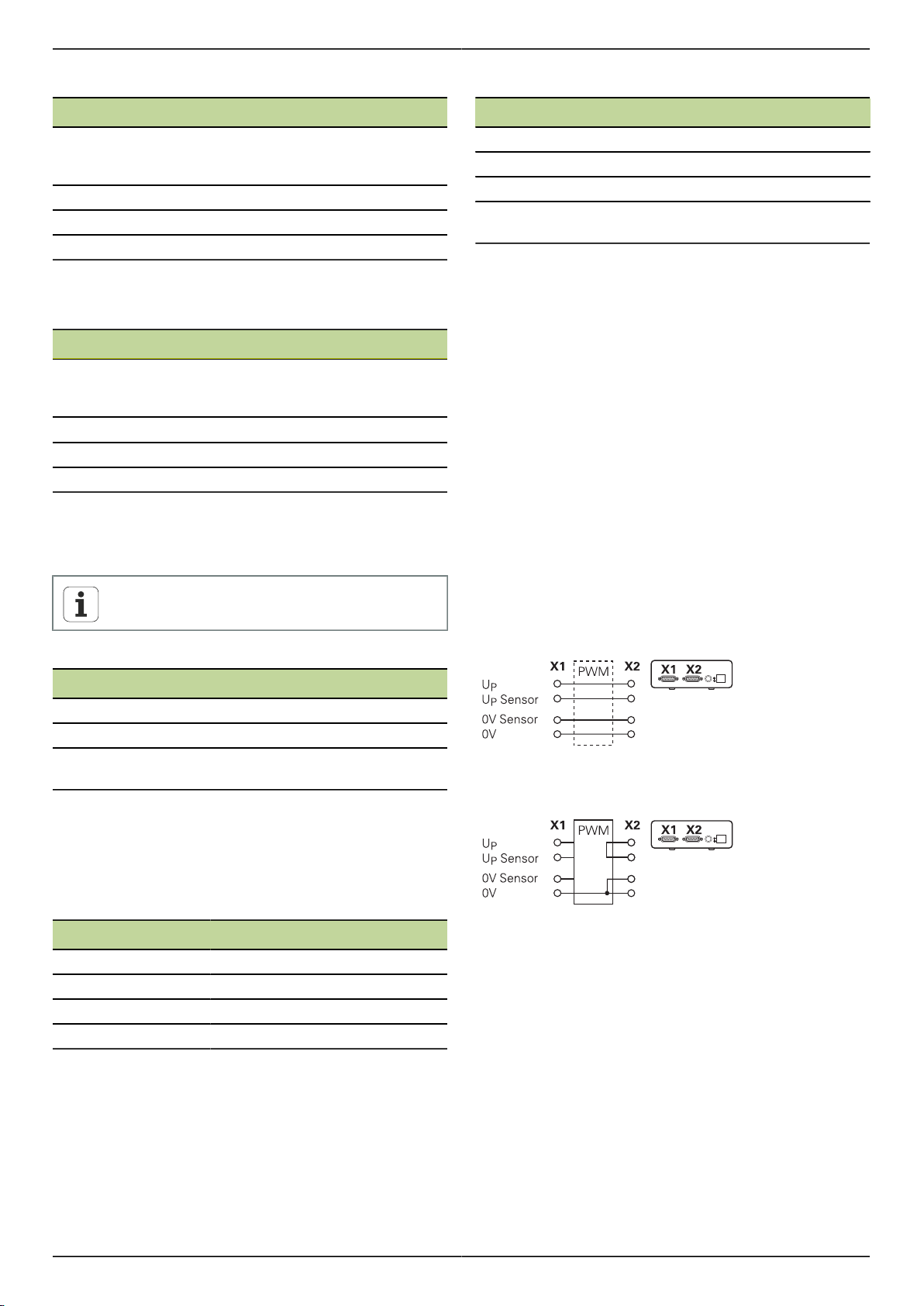
Manuale utente it PWM 20
Interfaccia EnDat/SSI
Pin Funzione
1, 3, 7, 9, 11, 14 segnali incrementali (solo per denomi-
nazione di ordinazione EnDat 01 e En-
Dat 02)
2, 4, 10, 12 tensione di alimentazione
5, 8, 13, 15 valori di posizione
6 schermatura interna
Configurazione dei segnali EnDat/SSI vedere "F".
Interfaccia Fanuc, Mitsubishi, Yaskawa o Panasonic
Pin Funzione
1, 3, 7, 9, 11, 14 segnali incrementali (se presenti solo
per fini di taratura; lasciare libero per
funzionamento normale)
2, 4, 10, 12 tensione di alimentazione
5, 8, 13, 15 valori di posizione
6 /
Configurazione dei segnali Fanuc vedere "G".
Configurazione dei segnali Mitsubishi vedere "H".
Configurazione dei segnali Yaskawa e Panasonic vedere "I".
Fanuc e Mitsubishi: non configurare i pin 5 e 13
per "one pair transmission".
Interfaccia 1 VPP/3 V
PP
Interfaccia TTL (con posizioni limite) e HTL
Pin Funzione
1, 3, 7, 9, 11, 14 segnali incrementali
2, 4, 10, 12 tensione di alimentazione
3, 13, 15 /
6, 8 segnali Limit
(se supportati dal sistema di misura)
Configurazione dei segnali TTL e HTL vedere "N".
Connettore X4
Configurazione dei segnali DRIVE-CLiQ vedere "P".
Uscita encoder X2
L'ingresso encoder X1 dello strumento è dotato di
collegamento galvanico con l'uscita encoder X2. I segnali
ovvero la configurazione dei pin sull'uscita corrispondono
ai relativi segnali in ingresso (in qualunque condizione di
misura).
Non si verifica alcuna separazione galvanica dei segnali. Le
linee di alimentazione e dei sensori vengono commutate
in funzione della relativa modalità operativa dal software
ATS V2.6 o superiore e possono essere collegate (vedere
esempi seguenti). Si garantisce sempre che la tensione di
alimentazione generata dallo strumento non sia presente su
X2.
Esempio 1 – Strumento in modalità misura passante
(l'encoder è alimentato dall'elettronica successiva) ovvero
software ATS non avviato:
Pin Funzione
1, 3, 7, 9, 11, 14 segnali incrementali
2, 4, 10, 12 tensione di alimentazione
5, 6, 8, 13, 15 altri segnali specifici per strumento
(commutazione interna agli strumenti)
Configurazione dei segnali 1 VPP con posizioni limite vedere
"J".
Configurazione dei segnali 1 VPP/Z1 vedere "K".
Configurazione dei segnali 1 VPP con clock/dati vedere "L".
Interfaccia 11 µAPP/25 µA
PP
Pin Funzione
1, 3, 7, 9, 11, 14 segnali incrementali
2, 4 tensione di alimentazione
5, 6, 8, 10, 12, 13, 15 /
6 schermatura interna
Configurazione dei segnali 11 µAPP (25 µAPP) vedere "M".
Esempio 2 – Lo strumento alimenta l'encoder tramite X1:
52
Page 51

PWM 20 Manuale utente it
Collegamento dei cavi degli encoder
Collegare in modo fisso gli encoder ai relativi attacchi.
Per connettori con viti: non serrare troppo le viti.
Non esercitare alcuna sollecitazione meccanica sui
collegamenti a innesto (ingresso encoder X4).
Lasciare liberi i pin e i conduttori inutilizzati.
4.4.1 Condizioni di messa a terra in modalità anello di regolazione chiuso
Lo strumento dispone di un alimentatore wide range
interno. Per tale ragione è richiesto il collegamento del
conduttore di protezione PE (terra) che è collegato anche
al corpo dello strumento. Se lo strumento è integrato
nell'anello di regolazione di una macchina CNC, esso
rappresenta un ulteriore punto di messa a terra che modifica
il concetto di schermatura.
Ciò si può impedire adottando le seguenti misure:
alimentazione dello strumento tramite un trasformatore
di isolamento oppure
alimentazione dello strumento a 24 V DC
Per l'analisi dei dati di misura dello strumento viene
collegato un PC alla porta USB dello strumento. Di norma
nel PC sono collegati tra loro 0 V e conduttore di protezione
(anche USB). Se lo strumento è integrato nell'anello di
regolazione di una macchina CNC, cambiano anche le
condizioni sul collegamento a 0 V.
Ciò si può impedire adottando le seguenti misure:
utilizzare come PC un laptop a batteria oppure
utilizzare un laptop con un alimentatore senza messa a
terra
4.4.2 Modalità anello di regolazione chiuso di una macchina CNC
Lo strumento può essere integrato tramite l'ingresso e
l'uscita encoder per fini diagnostici nell'anello di regolazione
di una macchina CNC (vedere "Uscita encoder X2",
Pagina 52).
AVVERTENZA
Pericolo di scosse elettriche!
Se lo strumento è integrato nell'anello di regolazione di
una macchina CNC, possono cambiare le condizioni di
messa a terra.
Adattare la messa a terra e le particolarità della
situazione di impiego.
A seconda della versione del software ATS e tenendo
conto delle indicazioni sulle condizioni di messa a terra lo
strumento può essere azionato nel Closed Loop.
Di norma è tuttavia necessario o raccomandato l'impiego di
un adattatore di segnale (ad es. SA 100, SA 110, …).
Collegamento dello strumento nella sequenza
seguente
Spegnere dapprima la macchina.
Allentare quindi i collegamenti.
4.5 Collegamento del computer
Al connettore USB X5 (USB tipo B) è possibile collegare un
computer tramite la relativa interfaccia USB 2.0 High Speed.
Collegare la porta USB del computer a X5 utilizzando un
cavo USB (vedere "Standard di fornitura", Pagina 49).
Per informazioni sulla posizione degli attacchi vedere "Retro
dello strumento", Pagina 50.
Piedinatura X5 vedere "Q".
4.6 Collegamento dello strumento esterno
A X3 è possibile collegare uno strumento esterno con
connettore Mini-DIN a 6 poli.
Collegare il connettore Mini-DIN dello strumento esterno
a X3 utilizzando un comune cavo con connettore MiniDIN a 6 poli.
Per informazioni sulla posizione degli attacchi vedere "Lato
frontale dello strumento", Pagina 50.
Piedinatura X3 vedere "O".
53
Page 52

Manuale utente it PWM 20
5 Funzionamento
AVVERTENZA
Pericolo di danni a macchinari e persone modificando le
tensioni degli encoder nel corso del funzionamento e con
assi verticali non fissati.
Non modificare alcun parametro o tensione encoder
sullo strumento mentre la macchina trasla o
nell'anello di regolazione si trova un PWM.
Fissare gli assi verticali contro la caduta prima di
eseguire misurazioni su di essi.
ATTENZIONE
Pericolo di danni a macchinari e persone nel caso di aree
di memoria non salvate.
Alcune interfacce, ad esempio EnDat, offrono la
possibilità di salvare nell'area di memoria del cliente i
dati specifici di macchine e impianti. Tali dati possono
contenere informazioni rilevanti per la sicurezza.
In caso di assistenza tenere presente che le aree di
memoria con dati specifici di macchine e impianti
devono essere salvate.
5.1 Accensione e spegnimento dello strumento
Accensione dello strumento
Per informazioni sulla posizione dell'interruttore di rete
vedere "Retro dello strumento", Pagina 50.
Portare l'interruttore di rete in posizione I.
Spegnimento dello strumento
5.2 Indicatori di stato e di errore
Gli stati di esercizio dello strumento sono visibili sui LED L1
e L2 presenti sul lato frontale dello strumento.
Per informazioni sulla posizione dei LED vedere "Lato
frontale dello strumento", Pagina 50.
LED Condizione Stato
L1 Off
On (verde)
L2 Off
On (verde)
non in stato di pronto
in stato di pronto
alimentazione dei sistemi di misura
disattivata
alimentazione dei sistemi di misura
attivata
5.3 Software ATS
PWM 20 consente di controllare dettagliatamente un
sistema di misura incrementale o assoluto (in funzione
dell'interfaccia anche nel Closed Loop).
Per l'utilizzo è possibile installare sul PC il software ATS
in dotazione. L'installazione e l'uso del software ATS è
descritto nel documento "Manuale utente ATS", vedere
"Indicazioni sulla lettura della documentazione", Pagina 45.
Requisiti di sistema raccomandati
PC IBM o PC 100% compatibile
Risoluzione video per software ATS: a partire da 1024 x
768
Windows Vista, Windows 7 (32 e 64 bit) o Windows 8
200 MByte di memoria libera su disco fisso (impiegando
il software ATS)
Memoria di lavoro > 2 GByte
USB 2.0 High Speed
Portare l'interruttore di rete in posizione 0.
L'interruttore di rete è protetto su tutti i poli.
Lo strumento può essere definitivamente
separato dalla sorgente di corrente soltanto
togliendo il connettore di rete.
54
Page 53

PWM 20 Manuale utente it
6 Manutenzione
Questo capitolo contiene soltanto la descrizione
completa degli interventi di manutenzione
dello strumento. Per descrivere gli interventi di
manutenzione che riguardano le unità periferiche,
consultare la documentazione delle relative unità
periferiche.
6.1 Pulizia
NOTA
Non utilizzare sostanze abrasive o aggressive oppure
solventi.
Non utilizzare un panno eccessivamente bagnato.
Pulire le superfici esterne con un panno imbevuto in
acqua e detergente neutro.
6.2 Programma di manutenzione
Il funzionamento dello strumento è per lo più esente da
manutenzione.
NOTA
Se danneggiato non riparare lo strumento né metterlo
più in funzione.
Far sostituire immediatamente dal costruttore
componenti elettrici danneggiati.
Interventi di manutenzione annuali
Verificare la leggibilità di tutte le marcature, iscrizioni e
simboli sull'apparecchio.
Controllare i collegamenti elettrici per verificarne la
funzionalità e l'eventuale
presenza di danni
Controllare la linea di rete
per verificarne l'isolamento
e i punti deboli
Controllare il conduttore di
protezione per verificarne
il corretto alloggiamento in
sede e la funzionalità
Eliminazione guasti
Contattare la filiale di assistenza HEIDENHAIN
Far sostituire le linee danneggiate, contattare la filiale di assistenza HEIDENHAIN
Sostituire la linea di rete secondo le specifiche
Far sostituire le linee di collegamento
7 Smontaggio, tutela ambientale e
smaltimento
Per lo smontaggio dalle macchine CNC è
necessario tenere eventualmente presente
particolari misure di sicurezza. Per ulteriori
informazioni vedere "Norme di sicurezza per
l'azionamento con e nelle macchine", Pagina 48.
Si applicano inoltre le norme di sicurezza
descritte per l'installazione, vedere "Installazione",
Pagina 50.
Operazioni preliminari
Portare l'interruttore di rete in posizione 0.
Staccare il connettore di rete dello strumento.
Staccare tutti i collegamenti dello strumento.
7.1 Smontaggio
Immagazzinaggio dopo lo smontaggio
Qualora lo strumento debba essere temporaneamente
immagazzinato dopo lo smontaggio, è necessario attenersi
alle disposizioni previste in materia ambientale, vedere "Dati
tecnici", Pagina 56.
Imballaggio dello strumento
Il reimballaggio deve essere il più possibile conforme a
quello originale:
Applicare tutti i componenti avvitati allo strumento allo
stesso modo in cui si trovavano alla consegna dello
strumento o reimballarli come erano imballati.
Inserire lo strumento negli inserti in cartone
conformemente allo stato di fornitura originale.
Disporre tutti gli altri componenti come ricevuti
nell'imballaggio originale, vedere "Standard di fornitura",
Pagina 49.
Allegare tutta la documentazione inclusa nello standard
di fornitura, vedere "Conservazione e inoltro della
documentazione", Pagina 46.
In caso di reso dello strumento al Servizio
Assistenza, gli accessori e i sistemi di misura
non devono essere spediti insieme allo
strumento.
Per poter garantire un funzionamento tracciabile,
preciso e perfetto, si raccomanda di inviare lo
strumento ogni 2 anni al centro di calibrazione di
HEIDENHAIN.
55
Page 54

Manuale utente it PWM 20
7.2 Tutela ambientale e smaltimento
NOTA
Smaltimento errato dello strumento, degli accessori e
delle periferiche!
Ne possono conseguire danni ambientali!
Non gettare tra i rifiuti domestici!
I rifiuti di apparecchiature elettriche e componenti
elettronici sono soggetti al trattamento quali rifiuti
speciali e devono essere smaltiti soltanto dai punti di
raccolta autorizzati.
Devono essere osservate le normative del relativo
Paese.
Informazioni dettagliati sulle regolamentazioni legali
possono essere richieste alle autorità competenti.
Per ulteriori chiarimenti in merito allo
smaltimento rivolgersi al costruttore!
8 Dati tecnici
Dati elettrici
Tensione di
alimentazione
Misurazione
di tensione e
corrente di alimentazione
Ingresso encoder X1
Connettore Sub-D a 15 poli, femmina
Supporto in funzione della versione del software ATS
impostabile da 2 V a 30 V con/senza regolazione remote
sense
Limitazione di corrente 750 mA
Nota sulla lunghezza dei cavi:
da 100 V a 240 V AC (±10%),
da 50 Hz a 60 Hz (±2 Hz)
ca. 20 W
24 V DC (±10%),
ca. 20 W
Tensione: ±0,5% (min. ±5 mV)
Corrente: ±2% (min. ±1 mA)
EnDat 2.1/
EnDat 2.2
1
1 V
PP
TTL
4
HTL
in caso di impiego di cavi HEIDENHAIN.
Deve essere rispettato il range della
tensione di alimentazione del sistema di
misura.
1
Lunghezza cavo: limite funzionale < 100 m,
a seconda della frequenza di clock
Rispetto limiti di prova < 2 m
(solo segnali incrementali)
Frequenza in ingresso segnali incrementali3: < 1000 kHz
Lunghezza cavo: limite funzionale < 150 m
Rispetto limiti di prova < 2 m
Frequenza in ingresso segnali incrementali2: < 1000 kHz
Lunghezza cavo: limite funzionale
< 100 m/50 m, a seconda della distanza
min. tra i fronti
Rispetto limiti di prova < 2 m
Frequenza in ingresso segnali incrementali:
< 1000 kHz
Distanza tra i fronti > 20 ns
Lunghezza cavo: limite funzionale
< 300 m, a seconda della distanza min. tra
i fronti
Rispetto limiti di prova < 2 m
Frequenza in ingresso segnali incrementali:
< 500 kHz
Distanza tra i fronti > 20 ns
56
Page 55

PWM 20 Manuale utente it
Ingresso encoder X1
11 µA
Fanuc,
Mitsubishi,
Yaskawa
Panasonic
SSI
1
2
3
4
1
PP
Lunghezza cavo: limite funzionale < 30 m
Rispetto limiti di prova < 2 m
Frequenza in ingresso segnali incrementali2: < 300 kHz
Lunghezza cavo: limite funzionale < 30 m
Lunghezza cavo: limite funzionale < 100 m
Rappresentazione negata dei segnali incrementali
Frequenza limite, che il software ATS riduce a 100 kHz per
determinate funzioni di misura
Se supportato dal sistema di misura collegato
HTL, solo per fini di assistenza tramite adattatore esterno del
segnale, ad es. ID 1093210-01
Uscita encoder X2
Connettore Sub-D a 15 poli, maschio
Modalità di
misura passante di X1
direttamente o tramite adattatore di
segnale SA xxx, in funzione della
versione ATS per
EnDat 2.1/EnDat 2.2
Fanuc/Mitsubishi
1 V
PP
TTL
11 µA
PP
Funzioni esterne X3
Connettore Mini-DIN a 6 poli, femmina
Emissione
MSB
Per EnDat 2.1/2.2
Limiti di prova 1 V
PP
Range di misura per tutte le frequenze in ingresso: 1,54 VPP.
Il range di misura esteso 2 (9,6 VPP) presenta tolleranze
più elevate. Per pochi sistemi di misura definiti (ad
esempio con interfaccia 3 VPP) il range di misura 2 viene
automaticamente impostato dal software ATS.
Frequenza in ingresso in kHz
Parametri
< 1 1 … 250 250 … 500
Ampiezza
del segnale
(A, B, R)
±2% ±3% ±4%
Errore
di simmetria
±0,002 ±0,006
–
Rapporto di
ampiezza del
segnale
±0,5% ±0,5%
–
Errore di simmetria TV1 e
TV2
±0,5° ±1° ±1,5°
Errore angolo
di fase
±0,5° ±1° ±1,5°
Larghezza
impulso di
riferimento
±2°
– –
Posizione
impulso di
riferimento
±2°
Limiti di prova 11 µA
PP
– –
Range di misura per tutte le frequenze in ingresso: 15,4
µA
PP
Il range di misura esteso 2 (96 µAPP) presenta tolleranze
più elevate. Per pochi sistemi di misura definiti (ad
esempio con interfaccia 25 µAPP) il range di misura 2 viene
automaticamente impostato dal software ATS.
Ingresso encoder X4
Connettore RJ-45 a 8+2 poli, femmina
DRIVE-CLiQ
1
DRIVE-CLiQ è un marchio registrato di Siemens Aktiengesellschaft,
sono supportati solo sistemi di misura HEIDENHAIN
1
Solo per sistemi di misura HEIDENHAIN
Interfaccia dati X5
USB USB 2.0 High Speed
1
Velocità di trasmissione USB inferiori possono comportare errori di
misura.
1
Frequenza in in-
gresso in kHz
Parametri
Ampiezza del segnale
(A, B, R) ±3% ±5%
Errore di simmetria ±0,006 ±0,006
Rapporto di ampiezza del
segnale ±2% ±2%
Errore di simmetria TV1 e
TV2 ±1,5° ±1,5°
Errore angolo di fase ±0,5° ±1,0°
Larghezza
impulso di riferimento ±6,0°
Posizione
impulso di riferimento ±3,0°
< 1 1 … 300
–
–
57
Page 56

Manuale utente it PWM 20
Limiti di prova TTL
Range di misura per tutte le frequenze in ingresso: 5 V
Frequenza in ingresso in kHz
Parametri
< 100 100 … 500 500 … 1000
Ampiezza del
segnale
Livello Low
Livello High
1
±0,05 V
±2%
– –
Errore di simmetria TV1 e
TV2
±0,5° ±1,5° ±2,5°
Errore angolo
di fase
±0,5° ±1,5° ±2,5°
Larghezza
impulso di
riferimento
±0,5° ±1,5° ±2,5°
Posizione
impulso di
riferimento
1
Ampiezza del segnale (Ua1, Ua1, Ua2, Ua2, Ua0, Ua0, UaS)
±0,5° ±1,5° ±2,5°
Limiti di prova HTL
Range di misura per tutte le frequenze in ingresso: da 10 a
30 V.
Condizioni ambientali
Temperatura di
lavoro
Temperatura di
immagazzinaggio
Grado di contaminazione
max
Grado di
protezione
EN 60529
da 0 °C a 45 °C, senza formazione di
condensa
da 0 °C a 70 °C, senza formazione di
condensa
II
IP 20
Dimensioni di collegamento
Vedere disegni di collegamento quotati "D".
Tutte le quote sono rappresentate in mm.
Frequenza in ingresso in kHz
Parametri
< 100 100 … 500
Ampiezza del
segnale
Livello Low
Livello High
1
±0,1 V
±3%
–
Errore di simmetria TV1 e
TV2
±0,5° ±1,5°
Errore angolo
di fase
±1,5° ±4°
Larghezza
impulso di
riferimento
±1,5° ±2,5°
Posizione
impulso di
riferimento
1
HTL, solo per fini di assistenza tramite adattatore esterno del
segnale, ID 1093210-01
±1,5° ±2,5°
58
Page 57

PWM 20 Manual de instrucciones de uso es
1
2
3
1 Acerca de este manual
Este manual contiene toda la información e instrucciones
de seguridad necesarias para montar e instalar el equipo
correctamente, así como para hacerlo funcionar, cuando se
maneje sin el software ATS
1.1 Información del modelo
Denominación del
producto
PWM 20 731626-01
El número de componente indicado es el
número que figura en la placa de características
El número de componente que figura en la
etiqueta del embalaje puede ser distinto al
número de componente indicado en la placa de
características, ya que puede ser que el equipo
se suministre en varias unidades de embalaje.
Etiqueta del modelo
La placa de características se encuentra en la parte
posterior del equipo
Ejemplo:
1
Denominación del producto
2
N° de pieza
3
Índice
Validez de la documentación.
En la parte inferior izquierda de la última página
de la documentación figura un número de
documento. La documentación es válida si
el número de documento concuerda con el
correspondiente número de documento que
figura en www.heidenhain.de .
Para ello, deben compararse la denominación
del producto, el número de pieza y el índice
indicados en la placa de características, con
los datos correspondientes que figuran en
www.heidenhain.de .
N° de pieza
1.2 Instrucciones para la lectura de la documentación
La tabla siguiente contiene las partes que componen la
documentación en el orden secuencial de su prioridad de
lectura.
ADVERTENCIA
El incumplimiento de las mismas puede ocasionar
accidentes con resultado de muerte, lesiones o daños
materiales.
Leer la documentación cuidadosamente y
completamente y conservarla para futuras consultas.
Documentación Descripción
Anexo Un anexo complementa o reempla-
za los contenidos correspondientes
del manual de instrucciones de uso
y, dado el caso, también del manual de instrucciones de instalación Si
este documento está contenido en
el suministro, deberá leerse primeramente. Todos los contenidos restantes de la documentación mantienen su validez.
Manual de instrucciones de uso
Instrucciones de
uso del software
ATS
Documentación
de los sistemas de
medición conectados, así como de la
periferia restante
El manual de instrucciones de uso
contiene toda la información e instrucciones de seguridad necesarias para montar, instalar y hacer funcionar correctamente el equipo y de
acuerdo con el fin al que está destinado. Está contenido en el alcance
del suministro y en el orden de prioridad de lectura ocupa la segunda
posición.
La documentación para la aplicación
del equipo con el software ATS puede descargarse en el área de descarga de www.heidenhain.de .
Estos documentos no están contenidos en el suministro. Forman
parte de los correspondientes envíos de los sistemas de medición y
periféricos
59
Page 58

Manual de instrucciones de uso es PWM 20
1.3 Conservación y divulgación de la documentación
Este manual debe guardarse en la proximidad inmediata
del puesto de trabajo y debe estar a disposición de todo el
personal en todo momento. El explotador del equipo deberá
informar al personal de donde se guarda este manual. Si el
manual se ha vuelto ilegible, el explotador del equipo deberá
pedir al fabricante un nuevo ejemplar.
Al transferir o revender el equipo a terceros, deberán
transferirse al nuevo propietario los documentos siguientes:
Anexo, en el caso de que se haya entregado con el
equipo
Manual de instrucciones de uso
1.4 Grupo destinatario del manual de instrucciones
Todas las personas que intervengan en uno de los
trabajos siguientes deberán leer y observar el manual de
instrucciones de uso:
Montaje
Instalación
Manejo
Mantenimiento
Desmontaje, protección medioambiental y eliminación
2 Seguridad
Para el funcionamiento del sistema, son aplicables las
medidas de seguridad reconocidas universalmente, como
las que se requieren en particular en la manipulación de
aparatos con tensión eléctrica. La no consideración de
estas prescripciones de seguridad puede tener como
consecuencia daños en el aparato o lesiones en las
personas.
Las prescripciones de seguridad pueden variar según cada
empresa. En el caso de conflicto entre el contenido de esta
guía rápida y las regulaciones internas de una empresa en la
que vaya a utilizarse este aparato, deben acatarse siempre
las regulaciones más severas.
2.1 Utilización conforme al uso previsto
El equipo podrá hacerse funcionar únicamente si se
encuentra en estado impecable y seguro. Está destinado
exclusivamente al uso siguiente:
Diagnosis y ajuste de los sistemas de medición de
HEIDENHAIN con interfaces absolutas e incrementales.
Cualquier otro uso del equipo o que vaya más allá de lo
indicado se considerará como no conforme al uso previsto y
puede originar riesgos y daños.
2.2 Utilización no conforme al uso previsto
Cualquier aplicación no indicada en "Utilización conforme
al uso previsto", se considera no conforme a lo previsto.
De los daños resultantes de dicho uso no previsto se
responsabilizará únicamente el explotador del equipo.
Además, las aplicaciones siguientes se consideran como no
admisibles:
Utilización de piezas, cables o conexiones defectuosas o
no conformes a las normas
Utilización en zonas sometidas a riesgo de incendio o de
explosión
Utilización sobrepasando las condiciones de
funcionamiento según "Características técnicas"
Modificaciones en el equipo o en la periferia sin la
autorización del fabricante
60
Page 59

PWM 20 Manual de instrucciones de uso es
2.3 Cualificación del personal
Para el montaje, la instalación, el manejo, el mantenimiento
y el desmontaje, se requiere un técnico especializado.
Para las tareas a realizar en el equipo, es imprescindible
que dicho técnico especializado esté suficientemente
informado con la ayuda de la documentación del equipo y
de la periferia conectada.
A continuación, se especifican las calificaciones:
El técnico especializado utiliza y maneja el equipo dentro
del marco del uso conforme a lo previsto. Dicho técnico
ha recibido la formación especial para el ámbito de trabajo
en el que realiza su actividad. Gracias a su formación
especializada, sus conocimientos y su experiencia, así como
su conocimiento de las Normas y disposiciones pertinentes,
el técnico especializado estará capacitado para ejecutar los
trabajos encomendados relativos a la respectiva aplicación,
y para reconocer y evitar de forma autónoma los posibles
riesgos. Dicho técnico deberá cumplir las disposiciones de
la normativa legal vigente para la prevención de accidentes.
2.4 Obligaciones del explotador
El explotador es el propietario del equipo y de la periferia o
ha alquilado ambos. En todo momento, será el responsable
de que se haga el uso conforme a lo previsto.
El explotador debe:
asignar las diferentes tareas en el equipo a personal
cualificado, apropiado y autorizado
instruir al personal de forma comprobable acerca de las
autorizaciones y tares "Cualificación del personal"
asegurar que el equipo se hace funcionar en un estado
impecable técnicamente
asegurar que el equipo quede protegido contra un uso
no autorizado
2.5 Instrucciones generales de seguridad
Las instrucciones de seguridad específicas, que
deben tenerse en cuenta en el equipo para las
diferentes actividades, están indicadas en los capítulos
correspondientes de este manual.
2.5.1 Clasificación de los avisos de advertencia
Los avisos de advertencia advierten contra los peligros en
la manipulación del equipo y proporcionan las instrucciones
para evitarlos. Se clasifican en función de la gravedad del
peligro y se subdividen en los grupos siguientes:
Tipos de advertencias
PELIGRO
Identifica una amenaza inmediata.
Si no se evita, la consecuencia son la muerte o lesiones
muy graves inmediatas.
ADVERTENCIA
Identifica una amenaza posible.
Si no se evita, la consecuencia pueden ser la muerte o
lesiones muy graves.
PRECAUCIÓN
Identifica una amenaza posible.
Si no se evita, la consecuencia pueden ser lesiones
leves o insignificantes.
INDICACIÓN
Identifica una situación posiblemente nociva.
Si no se evita, el equipo o algo de su entorno puede
resultar dañado.
Una casilla de información proporciona
informaciones importantes adicionales o
complementarias sobre una actividad o un
concepto.
Asimismo, pone de relieve situaciones o
circunstancias que pueden conducir a errores de
medición o funcionamientos erróneos.
61
Page 60
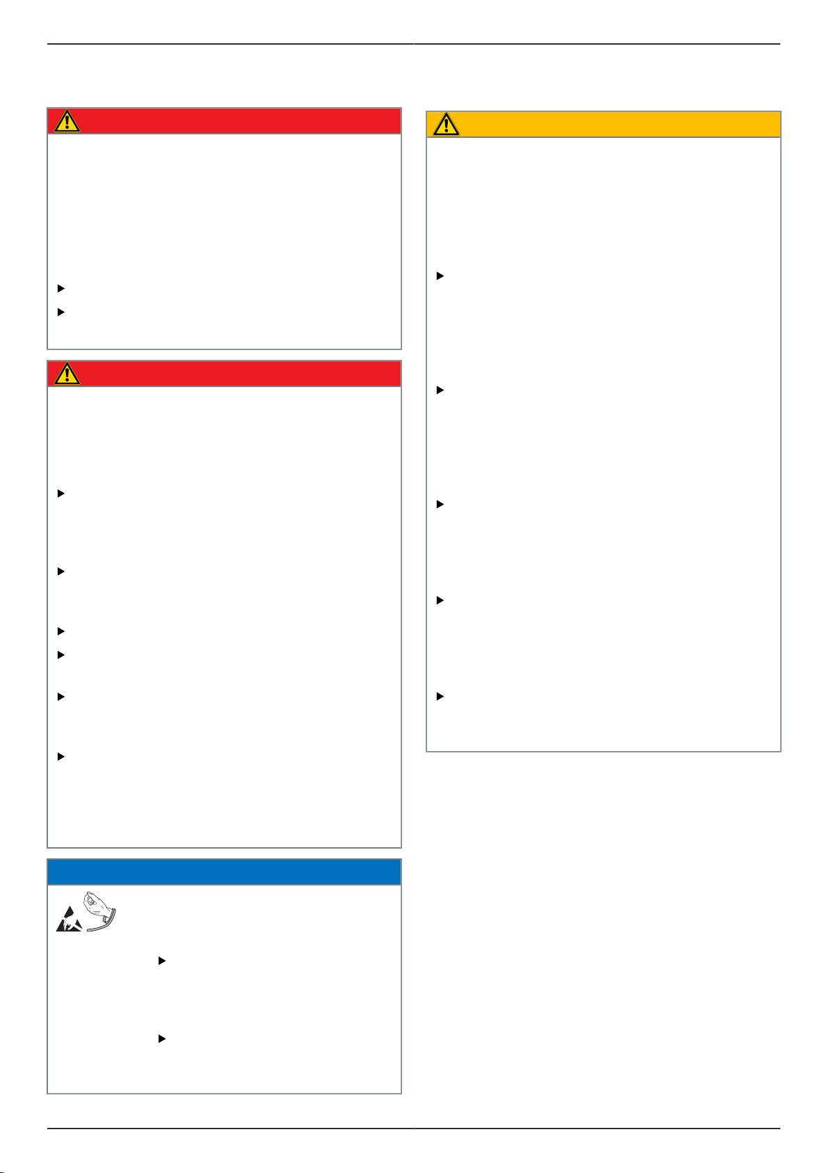
Manual de instrucciones de uso es PWM 20
2.5.2 Instrucciones de seguridad sobre el sistema eléctrico
PELIGRO
Al abrir el equipo, puede establecerse contacto con
partes sometidas a tensión eléctrica.
La consecuencia puede ser una descarga eléctrica,
quemaduras o la muerte. Además, al abrir el equipo
queda anulada la garantía, así como la responsabilidad
del fabricante sobre los accidentes, lesiones personales
y daños materiales resultantes de dicha apertura del
equipo.
La caja no debe abrirse en ningún caso.
Las intervenciones únicamente las podrá realizar el
fabricante.
PELIGRO
En el caso de contacto directo o indirecto con piezas
sometidas a tensión eléctrica, se producirá una
circulación de corriente peligrosa por el cuerpo.
La consecuencia puede ser una descarga eléctrica,
quemaduras o la muerte.
Los trabajos en el sistema eléctrico y en
componentes sometidos a tensión eléctrica deberán
encargarse a un especialista que cuente con la debida
formación.
Para la conexión a la red y para todas las conexiones
de las interfaces deberán emplearse exclusivamente
conectores y cables prefabricados según normas.
Impedir la formación de condensaciones
Si el equipo está dañado no debe repararse ni hacerse
funcionar
Deberá encargarse al fabricante la sustitución
inmediata de los componentes eléctricos
defectuosos.
Comprobar a intervalos de tiempo regulares todos los
cables conectados y todas las hembrillas de conexión
del equipo Las deficiencias, p. ej. conexiones flojas
o cables chamuscados, deberán subsanarse de
inmediato.
2.6 Medidas de seguridad durante el funcionamiento con y en las máquinas
ADVERTENCIA
Riesgo de lesiones personales y daños materiales debido
a un uso incorrecto.
Un manejo erróneo del NC, una programación incorrecta
del NC o unos valores de los parámetros de la máquina
incorrectos o no optimizados pueden originar un
comportamiento irregular de la máquina controlada por
NC.
Para poder valorar correctamente el comportamiento
irregular de una máquina controlada por NC deben
poseerse unos conocimientos sólidos sobre la
máquina, los accionamientos, los convertidores de
frecuencia y los NC, así como sobre su interacción
con los sistemas de medición.
Por lo tanto, en el manejo de las respectivas
máquinas, accionamientos, convertidores de
frecuencia y NC, además de las instrucciones
contenidas en este manual, deberán tenerse en
cuenta las normas de seguridad y de prevención de
accidentes especiales.
Al incorporar el equipo a una máquina o en otros
casos de aplicaciones especiales, todas las
medidas de seguridad que se indican en este
manual deben adaptarse a las particularidades de la
respectiva situación de aplicación.
En particular, deben realizarse las adaptaciones
necesarias en situaciones de puesta a tierra
modificadas, en el montaje y en el funcionamiento
conectado con el circuito de regulación de máquinas
controladas por NC.
Para el diagnóstico de fallos debe solicitarse
obligatoriamente asesoramiento al fabricante de la
máquina.
INDICACIÓN
62
Este producto contiene componentes que pueden quedar destruidos
debido a descargas electrostática
(ESD).
Deben observarse ineludiblemente las medidas de seguridad para el
manejo de componentes sensibles a
la ESD.
Nunca deberán tocarse las patillas
de conexión sin haberse realizado
una puesta a tierra adecuada.
Page 61

PWM 20 Manual de instrucciones de uso es
3 Montaje
3.1 Alcance del suministro
En el suministro del equipo básico se incluyen los artículos
siguientes:
Equipo
Cable de conexión a la red, de 3 m de longitud, con
enchufe de red de formato europeo
Manual de instrucciones de uso
Cable de conexión USB de 2 metros de longitud
CD con software ATS
Anexo (opcional, información adicional ver "Instrucciones
para la lectura de la documentación", página 59)
Opcionalmente, el equipo se puede suministrar
como componente de un sistema de diagnóstico
de un sistema de medición. En este caso,
el suministro comprende componentes
adicionales. Para información adicional, véanse
las instrucciones de uso del software ATS.
Desembalar el equipo
3.2 Lugar de instalación
INDICACIÓN
Daños en el equipo originados por una colocación
incorrecta.
Colocar el equipo únicamente en la posición
horizontal.
Elegir el lugar de instalación de modo que el equipo
sea fácilmente accesible durante el funcionamiento.
Procurar una buena ventilación.
Mantener libres y expeditas las aberturas de
ventilación posteriores y laterales y no impedir la
circulación de aire.
El equipo dispone de un ventilador controlado
por temperatura que se conecta cuando se
rebasa una temperatura interior máxima y se
desconecta una vez enfriado.
Para información sobre la posición de montaje, véase "C" en
la página de la cubierta desplegable.
Abrir la caja de cartón de embalaje por la parte superior.
Retirar el material de embalaje.
Extraer el contenido
Comprobar que el suministro esté completo.
Comprobar que el suministro no haya sufrido daños en el
transporte
En caso de haber sufrido daños durante el
transporte, conservar los materiales de embalaje
para ser sometido a examen y contactar
con el distribuidor de HEIDENHAIN o con el
fabricante del equipo. Esto aplica también para
las peticiones de repuestos.
Si se ha producido algún daño durante el transporte.
Solicitar al transportista que confirme los daños.
Guardar los materiales de embalaje para ser sometidos a
examen.
Informar al remitente sobre los daños.
Dado el caso, diríjase al distribuidor en su calidad de
intermediario
Contactar con el distribuidor de HEIDENHAIN o con el
fabricante del equipo en lo relativo a los repuestos.
Accesorios
En las instrucciones de uso del software ATS se encuentra
una visión global de artículos opcionales que para este
equipo se pueden solicitar a HEIDENHAIN.
63
Page 62

Manual de instrucciones de uso es PWM 20
4 Instalación
INDICACIÓN
¡Riesgo de daño de los componentes internos!
¡Realizar las conexiones de los cables sólo con el
aparato desconectado!
Según la variante de equipamiento, la instalación
puede variar en lo que respecta al modo de
proceder descrito en este capítulo. En el caso
de que el anexo entregado con el producto
contenga información sobre la instalación,
entonces la información allí descrita tendrá
prioridad frente a la información contenida en
este capítulo.
En las imágenes de asignaciones de las
patillas se representan de forma continua las
asignaciones de las conexiones en el equipo y no
las del conector.
La responsabilidad para cada sistema en el que
se utiliza este equipo recae en el explotador de
dicho sistema.
4.1 Descripción resumida del equipo
Parte frontal del equipo
Véase "A" en la página de la cubierta desplegable.
X1
X2
X3
X4
L1
L2
Entrada Sub-D de 15 polos para sistemas
de medición de HEIDENHAIN con
interfaz 11 µAPP/25 µA
PP
interfaz 1 VPP/3 VPP(1 VPP/Z1, 1 VPP con posiciones límite,
1 VPP con ciclo/datos)
Interfaz EnDat/SSI
Interfaz TTL con posiciones límite
Interfaz HTL (conexión únicamente para
realizar servicio técnico, mediante adaptador externo, p. ej. ID 1093210-01)
Interfaz Fanuc, Mitsubishi, Yaskawa o Panasonic
Salida Sub-D de 15 polos para el funcionamiento en bucle de las señales del sistema
de medición de X1
Conexión Mini-DIN de 6 polos para funciones externas
Conexión RJ-45 de 8+2 polos para sistemas
de medición con interfaz DRIVE-CLiQ
Indicación del estado para disponibilidad del
funcionamiento
Desconectado: no preparado para el funcionamiento
Conectado (verde): preparado para el funcionamiento
Indicación del estado para la alimentación
eléctrica del sistema de medición
Desconectado: alimentación eléctrica del
sistema de medición desconectada
Conectado (verde): alimentación eléctrica
del sistema de medición conectada
64
Parte posterior del equipo
Véase "B" en la página de la cubierta desplegable.
1
X5
X6
Conmutador de red
Hembrilla USB tipo B (USB 2.0), interfaz de
datos
Conexión en red
Page 63

PWM 20 Manual de instrucciones de uso es
4.2 Conectar la tensión de red
ADVERTENCIA
¡Peligro de descarga eléctrica!
Los equipos que no hayan sido puestos a tierra
correctamente pueden originar lesiones graves o la
muerte por electrocución.
En general, utilizar cable de red de 3 polos
Asegurar la correcta conexión del conductor de
protección en la instalación del edificio.
ADVERTENCIA
¡Existe riesgo de incendio si se emplean cables de red
que no cumplan los requisitos mínimos!
En general, emplear un cable de red que cumpla o
supere los requisitos mínimos indicados.
Conectar la conexión de red X6 con el cable de red
suministrado con el equipo a una toma de corriente con
conductor de protección.
La información sobre la situación de la conexión de
alimentación eléctrica se encuentra en la parte posterior del
equipover "Parte posterior del equipo", página 64.
Asignación de señales de la conexión de red X6 ver "R"
4.3 Descarga electrostática
INDICACIÓN
Este producto contiene componentes que pueden quedar destruidos
debido a descargas electrostática
(ESD).
Deben observarse ineludiblemente las medidas de seguridad para el
manejo de componentes sensibles a
la ESD.
Nunca deberán tocarse las patillas
de conexión sin haberse realizado
una puesta a tierra adecuada.
4.4 Conexión de los sistemas de medición
INDICACIÓN
Riesgo de daños en el equipo y daños en el sistema de
medición debidos a un rango de tensión de alimentación
incorrecto y a un cableado incorrecto.
Téngase en cuenta el rango de tensión de
alimentación del sistema de medición conectado.
Comprobar si el cable de interconexión entre el
sistema de medición y el equipo está cableado
correctamente.
El cable de interconexión entre el sistema de
medición y el equipo únicamente se podrá enchufar o
desenchufar en ausencia de tensión.
La responsabilidad sobre los daños que pudieran
originarse debido a la conexión y funcionamiento del
equipo con sistemas de medición que no proceden
de HEIDENHAIN, recae sobre el usuario.
Posibilidades de conexión
Los sistemas de medición con una interfaz de 15 polos
se conectan a la entrada X1 de los sistemas de medición
situada en la parte frontal del equipo
En el funcionamiento en bucle, para los sistemas de
medición con una interfaz de 15 polos se emplea la
salida X2 de los sistemas de medición
Los sistemas de medición con interfaces DRIVE-CLIC de
8+2 polos se conectan a la entradas X4 de los sistemas
de medición situadas en la parte frontal del equipo
Información sobre la situación de las conexiones ver
"Descripción resumida del equipo", página 64.
Las asignaciones de las conexiones del cable de
interconexión pueden consultarse en el catálogo.
Notas sobre la asignación de las señales de los
pines, en el anexo:
Pantalla del cable conectada a la carcasa;
UP = Tensión de alimentación
Sensor: dependiendo de los ajustes del
software ATS, los cables del sensor se
conectan internamente con con la respectiva
tensión de alimentación (Documento "Manual
de instrucciones de manejo del software
ATS", ver "Instrucciones para la lectura de la
documentación", página 59).
65
Page 64

Manual de instrucciones de uso es PWM 20
Interfaz EnDat/SSI
Pin Función
1, 3, 7, 9, 11, 14 Señales incrementales (únicamente
con la referencia de pedido EnDat 01 y
EnDat 02)
2, 4, 10, 12 Tensión de alimentación
5, 8, 13, 15 Valores de posición absolutos
6 Pantalla interior
Asignación de las señales EnDat/SSI ver "F".
Interfaz Fanuc, Mitsubishi, Yaskawa, Panasonic
Pin Función
1, 3, 7, 9, 11, 14 Señales incrementales (si existen, úni-
camente para calibración; en funciona-
miento normal no están asignadas)
2, 4, 10, 12 Tensión de alimentación
5, 8, 13, 15 Valores de posición absolutos
6 /
Asignación de señales Fanuc ver "G".
Asignación de señales Mitsubishi ver "H".
Asignación de señales Yaskawa y Panasonic ver "I".
Fanuc y Mitsubishi: Los pines 5 y 13 no están
asignados en caso de "one pair transmission".
Interfaz 1 VPP-/3 V
PP
Interfaz TTL (con posiciones límite) y HTL
Pin Función
1, 3, 7, 9, 11, 14 Señales incrementales
2, 4, 10, 12 Tensión de alimentación
3, 13, 15 /
6, 8 Señales Limit
(si el sistema de medición las contempla)
Asignación de señales TTL y HTL ver "N".
Conexión X4
Asignación de señales DRIVE-CLiQ ver "P".
Salida X2 de los sistemas de medición
La entrada de los sistemas de medición X1 del equipo está
conectada galvánicamente con la salida de los sistemas de
medición X2. Las señales o las asignaciones de pines en
la salida se corresponden con las respectivas señales en la
entrada (toma o reproducida activamente).
No se produce ninguna separación galvánica de las señales.
Dependiendo del respectivo modo de funcionamiento,
el software ATS conecta los cables de alimentación y de
los sensores a partir de la versión V2.6 y pueden estar
conectados (véanse los ejemplos siguientes). Siempre se
garantiza que la tensión de alimentación producida por el
equipo no está aplicada en X2.
Ejemplo 1 – Equipo en funcionamiento en bucle (el
sistema de medición recibe alimentación de la electrónica
conectada) o software ATS no activado:
Pin Función
1, 3, 7, 9, 11, 14 Señales incrementales
2, 4, 10, 12 Tensión de alimentación
5, 6, 8, 13, 15 otras señales dependientes del equipo
(Conmutación interna del equipo)
Asignación de señales 1 VPP con posiciones límite ver "J".
Asignación de señales 1 VPP/Z1 ver "K".
Asignación de señales 1 VSS con ciclo/datos ver "L".
Interfaz 11 µAPP/25 µA
PP
Pin Función
1, 3, 7, 9, 11, 14 Señales incrementales
2, 4 Tensión de alimentación
5, 6, 8, 10, 12, 13, 15 /
6 Pantalla interior
Asignación de señales 11 µAPP (25 µAPP) ver "M".
Ejemplo 2 – El equipo alimenta al sistema de medición a
través de X1:
66
Page 65

PWM 20 Manual de instrucciones de uso es
Conectar los cables de los sistemas de medición
Conectar los sistemas de medición sólidamente en las
conexiones respectivas
En conectores con tornillos: no apretar demasiado los
tornillos.
No ejercer solicitaciones de carga mecánicas en las
conexiones desenchufables (Entrada X4 de los sistemas
de medición).
¡No se deben ocupar los contactos o hilos no
ocupados!
4.4.1 Condiciones de la puesta a tierra en el funcionamiento en bucle
El equipo dispone de una fuente de alimentación
conmutada universal de amplio rango interna. Por este
motivo, es necesaria la conexión del conductor de
protección PE (tierra física de protección), que también
está interconectada con la carcasa del equipo. Si el equipo
se integra en el circuito de regulación de una máquina
controlada por NC, entonces ello representa un punto
de puesta a tierra adicional, que modifica el concepto de
apantallamiento.
Ello puede impedirse adoptando las medidas siguientes:
Alimentar el equipo a través de un transformador de
separación, o
alimentar el equipo con 24 Vcc
Para la evaluación de los datos de medición del equipo se
conecta un PC a la interfaz USB del equipo. Normalmente,
en el PC están interconectados entre sí los 0 V y la
conexión del conductor de protección (también USB). Si
el equipo se integra en el circuito de regulación de una
máquina controlada por NC, entonces cambian también las
condiciones en la conexión de 0 V.
Ello puede impedirse adoptando las medidas siguientes:
Como PC, debe emplearse un Laptop que funcione con
una batería, o
debe emplearse un Laptop con una fuente de
alimentación sin conexión del conductor de protección
4.4.2 Integración en el circuito de regulación de una máquina controlada por NC
El equipo puede integrarse en el circuito de regulación
de una máquina controlada por NC a través de la entrada
y salida del sistema de medición destinadas a fines de
diagnosis (ver "Salida X2 de los sistemas de medición",
página 66).
ADVERTENCIA
¡Peligro de descarga eléctrica!
Al incorporar el equipo en el circuito de regulación de una
máquina pueden cambiar las condiciones de la puesta a
tierra.
Adaptar la puesta a tierra y las particularidades de la
situación de utilización.
Dependiendo de la versión del software ATS, observando
las instrucciones sobre las condiciones de la puesta a
tierra, el equipo puede funcionar con circuito de regulación
cerrado.
Sin embargo, por principio es necesaria o recomendable la
utilización de un adaptador de la señal (p. ej. SA 100, SA 110,
…).
Conectar el equipo en el orden secuencial siguiente
Primeramente, parar la máquina.
A continuación, desenchufar las conexiones enchufables.
4.5 Conectar ordenador
En la conexión USB X5 (USB tipo B) puede conectarse un
ordenador a través de su interfaz de alta velocidad USB-2.0.
Conectar el puerto USB del ordenador a la conexión
X5 con la ayuda de un cable USB (ver "Alcance del
suministro", página 63).
Información sobre la situación de las conexiones ver "Parte
posterior del equipo", página 64.
Asignación de la conexión X5 ver "Q"
4.6 Conectar un equipo externo
A la conexión X3 se le puede conectar un equipo externo
con conexión Mini-DIN de 6 polos.
Con la ayuda de un cable comercial con conector MiniDIN de 6 polos, conectar la conexión Mini-DIN del
equipo externo con la conexión X3.
Información sobre la situación de las conexiones ver "Parte
frontal del equipo", página 64.
Asignación de la conexión X3 ver "O"
67
Page 66

Manual de instrucciones de uso es PWM 20
5 Manejo
ADVERTENCIA
Riesgo de lesiones personales y daños en la máquina se
se cambian las tensiones de los sistemas de medición
durante el funcionamiento y cuando los ejes verticales no
estén protegidos.
No modificar parámetros ni tensiones de los sistemas
de medición en el equipo mientras la máquina esté
trabajando y en el circuito de regulación exista un
PWM.
Por principio deben protegerse los ejes verticales
contra la caída antes de proceder a realizar
mediciones en dichos ejes.
PRECAUCIÓN
Riesgo de lesiones personales o daños en la máquina si
las áreas de memoria no están compensadas.
Algunas interfaces, p. ej. EnDat, ofrecen la posibilidad
de guardar datos de la máquina o datos específicos de
la instalación en el área de memoria del cliente. Dichos
datos pueden contener información relevante para la
seguridad.
Al realizar una reparación debe prestarse atención
a que las áreas de memoria estén compensadas
con los datos de la máquina o específicos de la
instalación.
5.1 Conexión y desconexión del equipo
Conexión del equipo
Información sobre la situación del interruptor de conexión a
la red ver "Parte posterior del equipo", página 64.
Poner el interruptor de conexión a la red en la posición I.
5.2 Indicaciones del estado y de los fallos
El estado de funcionamiento del equipo puede verse en los
LED L1 y L2 situados en la parte frontal del equipo.
Información sobre la situación de los diodos LED ver "Parte
frontal del equipo", página 64
LED Estado Estado
L1 Desconectado
Conectado
(verde)
L2 Desconectado
Conectado
(verde)
No operativo
Operativo
Alimentación eléctrica de los
sistemas de medición, conectada
Alimentación eléctrica de los
sistemas de medición, conectada
5.3 Software ATS
El PWM 20 sirve para la comprobación detallada en un
sistema de medición incremental o absoluta (dependiendo
de la interfaz, también en el circuito de regulación cerrado).
Para el manejo puede instalarse en el PC el software ATS
suministrado conjuntamente con el equipo. La instalación
y el manejo del software ATS se describe en el documento
"instrucciones de manejo del ATS", ver "Instrucciones para la
lectura de la documentación", página 59
Requisitos mínimos del sistema recomendados
PC IBM o PC 100% compatible
Resolución de la pantalla para software ATS, a partir de
1024 x 768
Windows Vista, Windows 7 (32 y 64 Bit) o Windows 8
200 MByte de memoria libre en el disco duro (cuando se
utiliza el software ATS)
Memoria RAM >2 GByte
USB 2.0 High Speed
Desconexión del equipo
Ajustar el interruptor de red a la posición 0.
El interruptor de red está protegido en todos sus
polos.
El equipo únicamente se puede separar de
forma definitiva de la fuente de alimentación
desenchufando el conector de conexión a la red.
68
Page 67

PWM 20 Manual de instrucciones de uso es
6 Mantenimiento
Este capítulo contiene únicamente la descripción
de los trabajos de mantenimiento. Para la
descripción de trabajos de mantenimiento
que afectan a los aparatos periféricos, véase
la documentación de los aparatos periféricos
correspondientes.
6.1 Limpieza
INDICACIÓN
No emplear disolventes o productos de limpieza
abrasivos o agresivos.
No utilizar paños empapados.
Limpiar las superficies exteriores con un paño
humedecido y un producto de limpieza suave.
6.2 Plan de mantenimiento
En gran medida, el equipo trabaja sin precisar
mantenimiento.
INDICACIÓN
7 Desmontaje, protección
medioambiental y eliminación
Al realizar el desmontaje desde las máquinas
controladas por NC deben observarse las
medidas de seguridad particulares. Información
adicional ver "Medidas de seguridad durante
el funcionamiento con y en las máquinas",
página 62.
Además son aplicables las instrucciones de
seguridad que se han descrito para la instalación,
ver "Instalación", página 64.
Preparación
Ajustar el interruptor de red a la posición 0.
Desenchufar la clavija de conexión a la red del equipo.
Desconectar todas las conexiones del equipo
7.1 Desmontaje
Almacenamiento tras el desmontaje
Si después del desmontaje el equipo debe disponerse en
un almacenamiento intermedio, deberán cumplirse las
disposiciones sobre condiciones medioambientales., ver
"Características técnicas", página 70.
Si el equipo está dañado no debe repararse ni hacerse
funcionar.
Deberá encargarse al fabricante la sustitución
inmediata de los componentes eléctricos
defectuosos.
Pasos del mantenimi-
Subsanación del fallo
ento anual
Comprobar la legibilidad
de todas las identificaciones, rotulaciones y símbolos que contiene el
equipo
Comprobar el correcto
funcionamiento de las
conexiones eléctricas y
que no presenten daños.
Comprobar que el cable
de conexión a la red no
presente un aislamiento
defectuoso o puntos débiles.
Comprobar el buen funcionamiento de la conexión del conductor de
protección y que esté bien apretada
Contactar con la delegación de servicio técnico de
HEIDENHAIN
Encargar la sustitución de los
cables defectuosos, póngase en contacto con la delegación de servicio técnico de
HEIDENHAIN
Sustituir el cable de conexión
a la red según la especificación.
Encargar la renovación de los
cables de conexión
Embalar el equipo.
El reembalaje deberá realizarse lo más igual que se pueda al
embalaje original:
Todas las piezas atornilladas deben colocarse en
el equipo tal como estaban colocadas cuando se
suministro el equipo, o volverlas a embalar tal como
estaban.
Embalar el equipo en las cajas de cartón tal como estaba
en el estado de suministro original.
Colocar todos los demás componentes en el embalaje
original tal como se habían recibido, ver "Alcance del
suministro", página 63.
Adjuntar toda la documentación dispuesta en el
embalaje suministrado, ver "Conservación y divulgación
de la documentación", página 60
Al devolver el equipo al servicio post-venta, los
accesorios y los sistemas de medición no deben
devolverse con el equipo.
Para poder garantizar un funcionamiento preciso,
sin errores y con trazabilidad, se recomienda
enviar el equipo cada 2 años al servicio de
calibración de HEIDENHAIN.
69
Page 68

Manual de instrucciones de uso es PWM 20
7.2 Protección medioambiental y eliminación
INDICACIÓN
¡Eliminación incorrecta del equipo, accesorios o
aparatos periféricos!
¡La consecuencia pueden ser daños medioambientales!
¡No eliminarlos con la basura doméstica!
Los componente electrónicos y la chatarra eléctrica
debe someterse a tratamiento especial de desechos
y solamente podrán se depositados en puntos de
recogida autorizados.
Deberá cumplirse la normativa del país respectivo.
La información precisa sobre las disposiciones legales
la proporcionan las autoridades administrativas
competentes (p. ej. organismos de gestión del agua y
medioambientales a nivel federal y de Länder).
¡En caso de que surjan preguntas sobre el
procedimiento de la eliminación, diríjase al
fabricante!
8 Características técnicas
Características eléctricas
Tensión de
alimentación
Medición de la
tensión y corriente de alimentación
Entrada del sistema de medición X1
Conector Sub-D de 15 polos, hembra
Compatibilidad en función de la versión del software ATS
Ajustable entre 2 V y 30 V con/sin regulación remote sen-
se
Limitación de la corriente 750 mA
Nota acerca de la longitud de los cables
100 Vca hasta 240 Vca (±10 %),
50 Hz hasta 60 Hz (±2 Hz)
aprox. 20 W
24 Vcc (±10 %),
aprox. 20 W
Tensión: ±0,5 % (mín. ±5 mV)
Corriente: ±2 % (mín. ±1 mA)
EnDat 2.1/
EnDat 2.2
1
1 V
PP
TTL
Utilizando cables de HEIDENHAIN. Es
preciso observar el rango de tensión de
alimentación eléctrica del sistema de
medición.
1
Longitud del cable: límite funcional
< 100 m, en función de la frecuencia de
reloj
cumplimiento de los límites de prueba
< 2 m
(únicamente señales incrementales)
Frecuencia de entrada de señales incrementales3: < 1000 kHz
Longitud del cable: límite funcional
< 150 m
cumplimiento de los límites de prueba
< 2 m
Frecuencia de entrada de señales incrementales2: < 1000 kHz
Longitud del cable: límite funcional
< 100 m/50 m, en función de la distancia
entre flancos mínima
cumplimiento de los límites de prueba
< 2 m
Frecuencia de entrada de señales incrementales: < 1000 kHz
Distancia entre flancos > 20 ns
70
Page 69

PWM 20 Manual de instrucciones de uso es
Entrada del sistema de medición X1
4
HTL
Longitud del cable: límite funcional
< 300 m, en función de la distancia entre
flancos mínima
cumplimiento de los límites de prueba
< 2 m
Frecuencia de entrada de señales incrementales: < 500 kHz
Distancia entre flancos > 20 ns
PP
1
Longitud del cable: límite funcional
11 µA
< 30 m
cumplimiento de los límites de prueba
< 2 m
Frecuencia de entrada de señales incrementales2: < 300 kHz
Fanuc,
Mitsubishi,
Yaskawa
Longitud del cable: límite funcional
< 30 m
Panasonic
SSI
Longitud del cable: límite funcional
< 100 m
1
Las señales incrementales se representan invertidas
2
Frecuencia límite, reducida por parte del software ATS a 100 kHz
para determinadas funciones de medición
3
si es compatible con el sistema de medición conectado
4
HTL únicamente para tareas de servicio técnico mediante un
adaptador de señal externo, p. ej., ID 1093210-01
Salida del sistema de mediciónX2
Conector Sub-D de 15 polos, macho
Funcionamien-
to em bucle de
X1
Directamente o mediante
adaptador de señalSA xxx, en función
de la versión ATS para
Interfaz de datos X5
USB USB 2.0 High Speed
1
Una velocidad de transmisión del USB más reducida puede
ocasionar errores en las medidas.
Límites de prueba 1 V
PP
1
Rango de medida para todas las frecuencias de entrada:
1,54 VPP.
El rango de medida ampliado 2 (9,6 VPP) presenta un
incremento de la tolerancia. El software ATS ajustan
automáticamente el rango de medida 2 en unos pocos y
determinados sistemas de medición (con por ejemplo 3
interfaces VPP).
Frecuencia de entrada en kHz
Parámetro
< 1 1 … 250 250 … 500
Magnitud de la
señal (A, B, R)
±2 % ±3 % ±4 %
Desviación de
la simetría
±0,002 ±0,006
–
Relación de
amplitudes de
señal
±0,5 % ±0,5 %
–
Desviación del
factor de utilización TV1 o
TV2
±0,5° ±1° ±1,5°
Desviación del
ángulo de fase
±0,5° ±1° ±1,5°
Anchura impulso de referencia
±2°
– –
Posición impulso de referencia
±2°
– –
EnDat 2.1/EnDat 2.2
Fanuc/Mitsubishi
1 V
pp
TTL
11 µA
PP
Funciones externas X3
Conector Mini-DIN de 6 polos, hembra
Salida MSB Para EnDat 2.1/2.2
Entrada del sistema de medición X4
Conector RJ-45 de 8+2 polos, hembra
DRIVE-CLiQ
1
DRIVE-CLiQ es una marca protegida de la sociedad anónima
Siemens, únicamente es compatible con los sistemas de medición
de HEIDENHAIN
1
Únicamente para los sistemas de medición de HEIDENHAIN
71
Page 70

Manual de instrucciones de uso es PWM 20
Límites de prueba 11 µA
PP
Rango de medida para todas las frecuencias de entrada:
15,4 µA
PP
El rango de medida ampliado 2 (9,6 µAPP) presenta un
incremento de la tolerancia. El software ATS ajustan
automáticamente el rango de medida 2 en unos pocos y
determinados sistemas de medición (con, por ejemplo,
interfaces 25 µAPP).
Frecuencia de
entrada en kHz
Parámetro
Magnitud de la señal (A, B, R) ±3 % ±5 %
Desviación de la simetría ±0,006 ±0,006
Relación de amplitudes de se-
ñal ±2 % ±2 %
Desviación del factor de utiliza-
ción TV1 o TV2 ±1,5° ±1,5°
Desviación del ángulo de fase ±0,5° ±1,0°
Anchura impulso de referencia ±6,0°
Posición impulso de referencia ±3,0°
< 1 1 … 300
–
–
Límites de prueba TTL
Rango de medida para todas las frecuencias de entrada: 5 V
Frecuencia de entrada en kHz
Parámetro
< 100 100 … 500 500 … 1000
Magnitud de la
1
señal
Low-Pegel
High-Pegel
±0,05 V
±2 %
– –
Desviación del
factor de utilización TV1 o TV2
±0,5° ±1,5° ±2,5°
Desviación del
ángulo de fase
±0,5° ±1,5° ±2,5°
Anchura impulso
de referencia
±0,5° ±1,5° ±2,5°
Posición impulso
de referencia
±0,5° ±1,5° ±2,5°
Límites de prueba HTL
Rango de medida para todas las frecuencias de entrada: 10
V a 30 V.
Frecuencia de entrada en kHz
Parámetro
< 100 100 … 500
Magnitud de la
1
señal
Low-Pegel
High-Pegel
±0,1 V
±3 %
–
Desviación del
factor de utilización TV1 o
TV2
±0,5° ±1,5°
Desviación del
ángulo de fase
±1,5° ±4°
Anchura impulso de referencia
±1,5° ±2,5°
Posición impulso de referencia
1
HTL únicamente para tareas de servicio técnico mediante un
adaptador de señal externo, ID 1093210-01
±1,5° ±2,5°
Condiciones del entorno
Temperatura
detrabajo
Temperatura
dealmacenamiento
Grado máximo
de suciedad
Tipo de
protección
EN 60529
0 °C a 45 °C, sin condensación
0 °C a 70°C, sin condensación
II
IP 20
Medidas de la conexión
Véase los dibujos de las medidas de la conexión "D".
Todas las medidas se representan en mm.
1
Magnitud de la señal (Ua1, Ua1, Ua2, Ua2, Ua0, Ua0, UaS)
72
Page 71

PWM 20 Bruksanvisning sv
1
2
3
1 Om denna manual
Denna manual innehåller all information och alla
säkerhetsinstruktioner för att montera och installera enheten
på korrekt sätt samt att använda enheten om den inte
används med ATC-software.
1.1 Information för modell
Produktbeteckning Artikelnummer
PWM 20 731626-01
Det angivna artikelnummer är det nummer
som finns angivet på typskylten. Artikelnumret
på förpackningens etikett kan avvika från
artikelnumret på typskylten eftersom
produkten kan levereras i flera olika typer av
förpackningskonfigurationer.
Typskylt
Typskylten befinner sig på enhetens baksida.
Exempel:
Dokumentation Beskrivning
Tillägg Ett tillägg kompletterar eller ersätter
motsvarande innehåll i bruksanvisningen och i förekommande all även
installationsanvisningen. När detta
dokument ingår i leveransen måste
det läsas först. Allt övrigt innehåll i
dokumentationen är fortfarande giltig.
Bruksanvisning Bruksanvisningen innehåller all in-
formation och alla säkerhetsinstruktioner för att montera, installera och
använda enheten på korrekt och avsett sätt. Den ingår i leveransen och
har näst högsta prioritet vid läsning.
Bruksanvisning
ATS-software
Dokumentation
för anslutna mätsystem samt övrig
kringutrustning
Dokumentationen för användningen av enheten tillsammans med
ATS-software kan laddas ned från
www.heidenhain.de .
Dessa dokument ingår inte i leveransen. De medlevereras respektive
mätsystem och kringutrustning
1.3 Arkivering och spridning av dokumentationen
1
Produktbeteckning
2
Artikelnummer
3
Index
Dokumentationens giltighet
På den sista sidan nere till vänster i
dokumentationen finns ett dokumentnummer.
Dokumentationen är giltig om dokumentnumret
återfinns med motsvarande dokumentnummer
på www.heidenhain.de och överensstämmer.
Dessutom måste produktbeteckningen,
artikelnumret och index på typskylten
kontrolleras med uppgifterna på
www.heidenhain.de och överensstämma.
1.2 Hur dokumentationen skall läsas
Följande tabell innehåller dokumentationens olika delar i
prioritetsordning vid läsning.
VARNING
Denna manual skall förvaras i arbetsplatsens omedelbara
närhet och alltid vara tillgänglig för hela personalen.
Verksamhetsutövaren skall informera personalen om var
denna manual förvaras. Om manualen har blivit oläslig
måste verksamhetsutövaren anskaffa en ersättningsmanual
från tillverkaren.
Vid överlåtelse eller försäljning av utrustningen till tredje part
måste följande dokument överlämnas till den nya ägaren:
Tillägg, om sådant har tillhandahållits
Bruksanvisning
1.4 Målgrupp för dokumentationen
Bruksanvisningen skall läsas och beaktas av alla personer
som är involverade i följande arbetsuppgifter:
Montage
Installation
Handhavande
Underhåll
Demontering, miljöskydd och avfallshantering
Underlåtenhet att följa kan leda till dödsolyckor,
personskador eller materiella skador.
Läs dokumentationen noggrant och fullständigt och
spara den för framtida behov.
73
Page 72

Bruksanvisning sv PWM 20
2 Säkerhet
För användning av systemet gäller allmänt vedertagna
säkerhetsföreskrifter som är nödvändiga speciellt vid
hantering av strömförande utrustning. Att inte följa dessa
säkerhetsåtgärder kan resultera i förstörd utrustning eller
personskada.
Säkerhetsföreskrifterna kan variera mellan olika företag. Om
det finns en konflikt mellan innehållet i denna manual och de
interna reglerna på företaget där enheten används, skall de
mer restriktiva reglerna gälla.
2.1 Avsett användningsområde
Enheten får bara användas om den är i felfritt och säkert
skick. Den är endast avsedd för följande användning:
Diagnos och justering av HEIDENHAIN-mätsystem med
absoluta och inkrementala gränssnitt
All annan användning eller användning därutöver av
utrustningen anses vara felaktig och kan leda till fara och
skador.
2.2 Felaktig användning
All användning som inte har nämnts i "Avsett
användningsområde", skall betraktas som felaktig.
Användaren ansvarar för skador som skulle kunna uppstå på
grund av detta.
Dessutom är följande användning inte tillåten:
Användning med defekta eller icke godkända delar,
kablar och kontakter
Användning i explosions- eller brandfarlig miljö
Användning utöver driftsvillkor enligt "Tekniska data"
Förändringar av enheten eller kringutrustningen utan
samtycke från tillverkaren
2.3 Personalens kvalifikationer
För montering, installation, drift, underhåll och demontering
av enheten behövs yrkeskvalifikationer som servicetekniker.
Serviceteknikern måste tillgodogöra sig tillräcklig
information för att arbeta med enheten och ansluten
kringutrustning via dokumentationen.
Nedan är kvalifikationerna specificerade:
Serviceteknikern använder och arbetar med enheten
inom ramen för det avsedda användningsområdet.
Serviceteknikern är är speciellt utbildad för det arbetsfält
denna är verksam inom. Serviceteknikern har via sin
yrkesutbildning, kunskap och erfarenhet samt kännedom
om gällande bestämmelser och normer förmågan att
utföra det arbete som tilldelats beträffande den aktuella
applikationen och på egen hand identifiera och undvika
potentiella risker. Serviceteknikern måste följa gällande
bestämmelser och föreskrifter för att undvika olyckor.
2.4 Skyldigheter för verksamhetsutövaren
Verksamhetsutövaren äger eller hyr enheten och
kringutrustningen. Han ansvarar alltid för att användningen
sker på avsett sätt.
Verksamhetsutövaren måste:
tilldela olika arbetsuppgifter vid enheten till kvalificerad,
lämplig och auktoriserad personal
instruera personalen beträffande befogenheter och
skyldigheter enligt "Personalens kvalifikationer"
säkerställa att utrustningen endast används i tekniskt
fullgott skick
säkerställa att utrustningen är skyddad mot obehörig
användning
74
Page 73

PWM 20 Bruksanvisning sv
2.5 Allmänna säkerhetsinstruktioner
De specifika säkerhetsinstruktionerna, som måste följas
vid olika typer av operationer i enheten, finns angivna i
respektive kapitel i denna manual.
2.5.1 Klassificering för varningar
Varningar varnar för risker vid användning av enheten
och ger information om hur dessa kan undvikas. De är
klassificerade efter hur allvarlig risken är och indelade i
följande grupper.
Noteringstyper
FARA
Beskriver en överhängande fara.
Om denna inte undviks är dödsfall eller allvarlig skada
en direkt följd.
VARNING
Markerar en eventuell fara.
Om denna inte undviks kan dödsfall eller allvarlig skada
bli följden.
VARNING
Beskriver en eventuell fara.
Om denna inte undviks kan lättare eller mindre skador
bli följden.
HÄNVISNING
Beskriver en eventuellt skadlig situation.
Om denna inte undviks kan enheten eller något i dess
omgivning skadas.
En informationsruta innehåller viktig ytterligare
eller kompletterande information kopplat till en
aktivitet eller ett koncept.
Den uppmärksammar också situationer eller
omständigheter som kan leda till mätfel eller
felaktig funktion.
2.5.2 Information om elsäkerhet
FARA
Öppning av enheten kan leda till kontakt med
strömförande delar.
Detta kan resultera i elektrisk stöt, brännskador eller
dödsfall. Dessutom upphävs garanti och tillverkarens
ansvar för därav uppkomna olyckor, personskador och
materiella skador om enheten öppnas.
Öppna inte höljet under några som helst
omständigheter.
Ingrepp får bara utföras av tillverkaren.
FARA
Direkt eller indirekt kontakt med spänningsförande delar
leder till farlig ström genom kroppen.
Detta kan resultera i elektrisk stöt, brännskador eller
dödsfall.
Arbete med el och strömförande komponenter får
bara utföras av behörig elektriker.
Använd enbart kabel och kontakter som är tillverkade
enligt godkänd standard för nätanslutning och
anslutning av alla gränssnitt.
Förhindra kondens.
Reparera inte och använd inte längre enheten vid
skador
Låt tillverkaren byta ut defekta elektriska
komponenter direkt.
Kontrollera regelbundet alla anslutna kablar och
anslutningskontakter på enheten. Åtgärda defekter
såsom lösa anslutningar eller skadade kablar
omedelbart.
HÄNVISNING
Denna produkt innehåller komponenter som kan förstöras av elektrostiskt urladdning (ESD).
Säkerhetsföreskrifter för hantering
av ESD-känsliga komponenter måste
beaktas.
Vidrör aldrig anslutningsstift utan
korrekt jordning.
75
Page 74

Bruksanvisning sv PWM 20
2.6 Säkerhetsåtgärder vid arbete med och i maskiner
VARNING
Risk för allvarliga personskador och materiella skador vid
felaktig användning.
Felaktig användning av NC, felaktig NC-programmering,
felaktiga eller icke optimerat maskinparametervärden kan
leda till felaktig funktion i den NC-styrda maskinen.
För att kunna bedöma problem i en NC-styrd
verktygsmaskin, måste grundläggande kunskaper om
maskiner, motorer, servoförstärkare och NC, samt
deras samverkan mätsystemen finnas.
Utöver dessa anvisningar behöver särskilda
föreskrifter för säkerhet och förebyggande av
olycksfall i hanteringen av respektive maskin, motorer,
servoförstärkare och NC beaktats!
Vid installation av enheten i en maskin eller vid andra
speciella applikationer måste alla säkerhetsföreskrifter
som finns angivna i denna instruktion anpassas till
den aktuella användningssituationen!
Framför allt måste nödvändiga justeringar genomföras
på grund av förändrade jordningsförhållanden vid
installation och serieinkoppling i numeriskt styrda
maskiners reglerkretsar.
Vid feldiagnos måste maskintillverkaren konsulteras.
3 Montage
3.1 Leveransomfång
Följande komponenter är inkluderade i leveransen av
grundutförandet:
Enhet
3 m lång nätkabel med Euro-nätkontakt
Bruksanvisning
2 m lång USB-anslutningskabel
CD med ATS-software
Tillägg (optional, ytterligare information se "Hur
dokumentationen skall läsas", Sida 73)
Som option kan enheten levereras som en
ingående del i ett paket för mätsystemsdiagnos.
I detta fall ingår det ytterligare komponenter
i leveransen. Ytterligare information Se
bruksanvisning ATS-software
Packa upp enheten
Öppna förpackningskartongens topp.
Ta bort förpackningsmaterialet.
Ta ut innehållet.
Kontrollera att leveransen är komplett.
Kontrollera att leveransen inte är transportskadad.
Spara förpackningsmaterialet för undersökning
vid en transportskada och kontakta
HEIDENHAIN-återförsäljaren eller tillverkaren
av utrustningen. Detta gäller även vid behov av
reservdelskomponenter.
När en transportskada föreligger
Tillse att speditören bekräftar skadorna.
Samla förpackningsmaterialet för undersökning.
Informera avsändaren om skadorna.
Kontakta vid behov återförsäljaren som mellanhand.
Konkta HEIDENHAIN-återförsäljaren eller utrustningens
tillverkare beträffande reservdelskomponenter.
Tillbehör
En översikt över tilläggsartiklar till denna enhet som kan
beställas av HEIDENHAIN finns i bruksanvisningen för ATSsoftware.
76
Page 75

PWM 20 Bruksanvisning sv
3.2 Placering
HÄNVISNING
Skador på enheten på gund av felaktig placering.
Placera alltid enheten horisontellt.
Välj placering så att enheten är lätt åtkomlig under
drift.
Säkerställ god ventilation.
Håll ventilationsöppningarna på baksidan och sidorna
fria och hindra inte luftflödet.
Enheten är försedd med en temperaturstyrd fläkt
som aktiveras när en maximal innertemperatur
uppnås och sedan stängs av efter avkyldning.
Information om monteringsläge, se "C" på det utfällbara
försättsbladet.
4 Installation
HÄNVISNING
Risk för skador på interna komponenter!
Koppla bara in och ur kontakter när enheten är
avstängd.
Beroende på utrustningsvarianten kan
installationen avvika från det förfarande som
beskrivs i detta kapitel. Om tillägget som
levereras med produkten innehåller information
om installationen, har informationen där
företräde före den information som anges i detta
kapitel.
I bilderna med pin-beläggning visas
genomgående beläggning för anslutning på
enheten och inte kabelkontakten.
Ansvaret för alla system där denna enhet
används, ligger hos den som använder systemet.
77
Page 76

Bruksanvisning sv PWM 20
4.1 Produktöversikt
Enhetens framsida
Se "A" på den främre utvikssidan.
X1
X2
X3
X4
L1
L2
Enhetens baksida
Se "B" på den främre utvikssidan.
15-polig Sub-D-ingång för HEIDENHAINmätsystem med
11 µAPP/25 µAPP-gränssnitt
1 Vpp/3 VPP-gränssnitt
(1 VPP/Z1, 1 VPP med gränslägen,
1 VPP med Takt/Data)
EnDat/SSI-gränssnitt
TTL-gränssnitt med gränslägen
HTL-gränssnitt (anslutning enbart för
serviceändamål via extern adapter,
t.ex. ID 1093210-01)
Fanuc-, Mitsubishi-, Yaskawa- eller Panasonic-gränssnitt
15-polig Sub-D-utgång för utmatning av mätsystemssignalerna från X1 vid serieinkoppling
6-polig Mini-DIN-anslutning för externa funktioner
8+2-polig RJ-45-anslutning för mätsystem
med DRIVE-CLiQ-gränssnitt
Statusindikering för driftklar
Av: Ej driftklar
På (grön): Driftklar
Statusindikering för mätsystemsförsörjning
Av: Mätsystemsförsörjning avstängd
På (grön): Mätsystemsförsörjning aktiverad
4.2 Anslut nätspänning
VARNING
Risk för elektrisk stöt!
Felaktigt jordade enheter kan resultera i allvarliga skador
eller dödsfall på grund av elektrisk stöt.
Använd alltid 3-polig nätkabel.
Säkerställ att korrekt skyddsledaranslutning finns i
fastighetsinstallationen.
VARNING
Brandfara vid användning av nätkabel som inte uppfyller
minimikraven!
Använd alltid en nätkabel som uppfyller eller
överträffar angivna minimikrav.
Anslut nätspänning till enheten med den levererade
nätkabeln via ett vägguttag med skyddsjord.
Informationen om nätanslutningens placering på enhetens
baksida se "Enhetens baksida", Sida 78.
Nätanslutningens signalbeläggning X6 se "R".
4.3 Elektrostatisk urladdning
HÄNVISNING
Denna produkt innehåller komponenter som kan förstöras av elektrostiskt urladdning (ESD).
Säkerhetsföreskrifter för hantering
av ESD-känsliga komponenter måste
beaktas.
Vidrör aldrig anslutningsstift utan
korrekt jordning.
1
X5
X6
78
Strömbrytare
USB-kontakt Typ B (USB 2.0), datagränssnitt
Nätanslutning
Page 77

PWM 20 Bruksanvisning sv
4.4 Ansluta mätsystem
HÄNVISNING
Risk för skador på enheten och mätsystem på grund
av felaktig nivå på matningsspänningen eller felaktig
inkoppling!
Beakta det anslutna mätsystemets
matningsspänningsområde.
Kontrollera att kabeln mellan mätsystemet och
enheten är korrekt konfigurerad.
Koppla bara in och ur anslutningskabeln mellan
mätsystemet och enheten med matningsspänningen
avstängd.
Användaren bär all risk vid anslutning och användning
av enheten tillsammans med mätsystem som inte har
tillverkats av HEIDENHAIN.
Anslutningsmöjligheter
Mätsystem med 15-poligt gränssnitt ansluts till
mätsystemsingången X1 på enhetens framsida
Vid serieinkoppling används mätsystemsutgången X2 vid
mätystem med 15-poligt gränssnitt
Mätsystem med 8+2-poligt DRIVE-CLiQ-gränssnitt
ansluts till mätsystemsingången X4 på enhetens
framsida
Information om anslutningskontaktens placering se
"Produktöversikt", Sida 78.
Anslutningskabelns pin-konfiguration återfinns i katalogen.
Information om pinkonfiguration och
signalbeläggning i appendix:
Kabelskärm skall vara ansluten till höljet;
UP = Spänningsförsörjning
Sensor: Beroende på inställningen i ATSsoftware är sensorledarna internt förbundna
till spänningsförsörjningen (dokument
"Bruksanvisning ATS-software", se "Hur
dokumentationen skall läsas", Sida 73).
EnDat/SSI-gränssnitt
Pin Funktion
1, 3, 7, 9, 11, 14 Inkrementella signaler (endast vid mo-
dellbeteckning EnDat 01 och EnDat 02)
2, 4, 10, 12 Spänningsförsörjning
5, 8, 13, 15 Positionsvärde
6 Innerskärm
Signalbeläggning EnDat/SSI se "F".
Fanuc-, Mitsubishi-, Yaskawa-, Panasonic-gränssnitt
Pin Funktion
1, 3, 7, 9, 11, 14 Inkrementella signaler (om sådana
finns, endast för justeringsändamål;
används inte i normal drift)
2, 4, 10, 12 Spänningsförsörjning
5, 8, 13, 15 Positionsvärde
6 /
Signalbeläggning Fanuc se "G".
Signalbeläggning Mitsubishi se "H".
Signalbeläggning Yaskawa och Panasonic se "I".
Fanuc och Mitsubishi: Pin 5 och 13 används inte
vid "one pair transmission".
1 VPP-/3 VPP-gränssnitt
Pin Funktion
1, 3, 7, 9, 11, 14 Inkrementella signaler
2, 4, 10, 12 Spänningsförsörjning
5, 6, 8, 13, 15 ytterligare enhetsberoende signaler
(växling internt i enheten)
Signalbeläggning 1 VPP med gränslägen se "J".
Signalbeläggning 1 VPP/Z1 se "K".
Signalbeläggning 1 VPP med takt/data se "L".
11 µAPP/25 µAPP-gränssnitt
Pin Funktion
1, 3, 7, 9, 11, 14 Inkrementella signaler
2, 4 Spänningsförsörjning
5, 6, 8, 10, 12, 13, 15 /
6 Innerskärm
Signalbeläggning 11 µAPP (25 µAPP) se "M".
79
Page 78

Bruksanvisning sv PWM 20
TTL- (med gränslägen) och HTL-gränssnitt
Pin Funktion
1, 3, 7, 9, 11, 14 Inkrementella signaler
2, 4, 10, 12 Spänningsförsörjning
3, 13, 15 /
6, 8 Limit-signal
(när mätsystemet stödjer det)
Signalbeläggning TTL och HTL se "N".
Anslutning X4
Signalbeläggning DRIVE-CLiQ se "P".
Mätsystemsutgång X2
Enhetens mätsystemsingång X1 är galvaniskt förbunden
med mätsystemsutgången X2. Signaler resp. pinkonfigurationen på utgången motsvarar respektive signal på
ingången (avtappad eller aktivt simulerad).
Det finns inte någon galvanisk separation mellan signalerna.
Försörjnings- och sensorledarna aktiveras beroende på
driftarten av ATS-software från V2.6 och kan vara förbundna
med varandra (se följande exempel). Det är alltid helt säkert
att den matningsspänning som skapas av enheten inte läggs
ut på X2.
Exempel 1 – enheten är serieinkopplad (mätstystemet
försörjs av efterföljande elektronik) eller ATS-software har
inte startats:
Anslut mätystemets kabel
Anslut mätsystemet till respektive kontaktanslutning.
Vid kontakter med skruvar: dra inte åt skruvarna för hårt.
Applicera inte någon mekanisk belastning på
kontaktanslutningen (mätsystemsingång X4).
Stift eller ledare som inte används får inte
anslutas.
4.4.1 Jordningsförhållanden vid serieinkoppling
Enheten har ett inbyggt switchat wide range nätaggregat.
Därför är anslutning av skyddsledare PE (skyddsjord)
som är förbunden med enhetens hölje nödvändig.
Används enheten i en NC-styrd maskins reglerkrets,
skapas därmed en ytterligare jordpunkt som förändrar
skärmningskonceptet.
Detta kan förhindras via följande åtgärder:
Försörj enheten via en isolertrafo, eller
Försörj enheten med DC 24 V
För utvärdering av mätdata från enheten ansluts en
PC till enhetens USB-gränssnitt. Vanligen är 0 V i PC:n
förbunden till skyddsjordsanslutningen (även USB). Används
enheten i en NC-styrd maskins reglerkrets, förändras även
förhållandet för 0-V-anslutning.
Detta kan förhindras via följande åtgärder:
Använd en batteridriven Laoptop som PC, eller
Använd en Laptop med nätdel som saknar
skyddsledaranslutning
Exempel 2 – enheten försörjer mätsystemet via X1:
80
Page 79

PWM 20 Bruksanvisning sv
4.4.2 Serieinkoppling i en NC-styrd maskins reglerkrets
För felsökning kan enheten kopplas in en NC-styrd
maskins reglerkrets via mätsystystemsingången och
mätsystemsutgången (se "Mätsystemsutgång X2", Sida 80).
VARNING
Risk för elektrisk stöt!
När du installerar enheten i en NC-styrd maskins
reglerkrets kan jordningsförhållanden ändras.
Anpassa jordningen och användningsförhållandenas
specifika behov.
Beroende på ATS-programvarans version och anpassning
till informationen om jordningsförhållandena kan enheten
användas i en sluten reglerkrets.
Som grundregel är dock en signaladapter (t.ex. SA 100, SA
110, …) nödvändig resp. rekommenderad.
Anslut enheten i följande ordningsföljd
Stäng först av maskinen.
Lossa sedan kontakterna.
4.5 Ansluta dator
Via USB-kontaktanslutning X5 (USB Typ B) kan en dator med
USB-2.0-High-Speed-gränssnitt kopplas in.
Anslut datorns USB-port med hälp av en USB-kabel (se
"Leveransomfång", Sida 76) till kontaktanslutning X32.
Information om anslutningskontaktens placering se
"Enhetens baksida", Sida 78.
Kontaktbeläggning X5 se "Q".
4.6 Anslut extern enhet
En extern enhet med 6-polig Mini-DIN-anslutning kan
anslutas till kontakt X3.
Anslut den externa enhetens Mini-DIN-kontaktanslutning
via en vanlig standardkabel med 6-polig Mini-DIN-kontakt
till kontaktanslutning X3.
5 Handhavande
VARNING
Risk för maskin- eller personskador vid ändring av
mätsystemets spänning under drift och vid vertikala axlar
utan motvikt eller annat skydd.
Ändra inte några parametrar eller mätsystemets
spänning i enheten samtidigt som maskinen körs och
en PWM befinner sig i reglerkretsen.
Säkra vertikala axlar från så att de inte kan falla innan
mätning utförs i dessa axlar.
VARNING
Risk för maskin- eller personskador om minnesområden
inte harmoniseras.
Vissa gränssnitt, t.ex. EnDat, erbjuder möjlighet
spara maskin- eller anläggningsspecifika data i
kundens minnesområde. Dessa data kan innehålla
säkerhetsrelevant information.
I servicefall måste man säkerställa att minnet
harmoniseras med maskin- eller anläggningsspecifika
data.
5.1 Starta och stänga av enheten
Starta enheten
Information om strömbrytarens placering se "Enhetens
baksida", Sida 78.
Växla strömbrytaren till position I.
Stänga av enheten
Växla strömbrytaren till position 0.
Strömbrytaren är mångpoligt avsäkrad.
Enheten kan bara separeras fullständigt från
strömkällan genom att dra ut nätkontakten.
Information om anslutningskontaktens placering se
"Enhetens framsida", Sida 78.
Kontaktbeläggning X3 se "O".
81
Page 80

Bruksanvisning sv PWM 20
5.2 Status- och felindikering
Enhetens driftstatus indikeras i LED L1 och L2 på enhetens
framsida.
Information LED-placeringen se "Enhetens framsida",
Sida 78.
LED Status Status
L1 Av
På (grön)
L2 Av
På (grön)
Ej driftklar
Driftklar
Mätsystemsförsörjning avstängd
Mätsystemsförsörjning aktiverad
5.3 ATS-software
PWM 20 används för detaljerad kontroll av inkrementella
resp. absoluta mätsystem (beroende på vilken typ av
mätsystem även i sluten reglerkrets).
För användning kan den medlevererade ATS-programvaran
installeras i en PC. Installation och handhavande av ATSprogramvaran beskrivs i dokumentet "ATS-bruksanvisning",
se "Hur dokumentationen skall läsas", Sida 73.
Rekommenderade systemförutsättningar
IBM-PC eller 100 % kompatibel PC
Bildskärmsupplösning för ATS-software: från 1024 x 768
Windows Vista, Windows 7 (32 och 64 Bit) eller
Windows 8
200 MByte ledigt minne på hårddisken (vid användning
av ATS-programvaran)
RAM-minne > 2 GByte
USB 2.0 High Speed
6 Underhåll
Detta kapitel innehåller enbart beskrivning
av underhållsarbete avseende enheten. För
beskrivning av underhållsarbete avseende
kringutrustning, se dokumentationen för
respektive kringutrustning
6.1 Rengöring
HÄNVISNING
Använd inte några slipande eller aggressiva
rengöringsmedel och inte heller några lösningmedel.
Använd inte en trasa som är så blöt att det droppar.
Tvätta av utvändiga ytor med en trasa som är lätt fuktad
med vatten och ett milt rengöringsmedel.
6.2 Underhållsplan
Enheten är i stort sett underhållsfri.
HÄNVISNING
Reparera inte och använd inte längre en skadad
enhet.
Låt tillverkaren byta ut defekta elektriska
komponenter direkt.
Årliga underhållssteg Felåtgärd
Kontrollera att alla markeringar, etiketter och symboler på instrumentet är
läsbara
Kontrollera de elektriska
anslutningarnas funktion
och att de inte skadade
Kontrollera nätsladden så
att isoleringen inte är skadad eller andra brister
Kontrollera att skyddsledaren sitter fast ordentligt
och dess funktion
Kontakta HEIDENHAIN serviceavdelning
Kontakta HEIDENHAIN serviceavdelning för att byta felaktiga ledare
Byt ut nätsladden i enlighet
med specifikationen
Byt till nya anslutningskablar
82
För att säkerställa en spårbar, korrekt och felfri
funktion, rekommenderas att skicka enheten vart
annat år till HEIDENHAIN för kalibrering.
Page 81

PWM 20 Bruksanvisning sv
7 Demontering, miljöskydd och
avfallshantering
Vid demontering av NC-styrda maskiner
måste i förekommande fall särskilda
försiktighetsåtgärder följas. Ytterligare
information se "Säkerhetsåtgärder vid arbete
med och i maskiner", Sida 76.
Dessutom gäller säkerhetsinstruktionerna som
har beskrivits för installation, se "Installation",
Sida 77.
Förberedelse
Växla strömbrytaren till position 0.
Koppla ur nätkontakten från enheten.
Lossa alla anslutningskontakter från enheten.
7.1 Demontering
Lagring efter demontering
Skall enheten lagras efter demonteringen måste
bestämmelserna för omgivningsförhållanden iakttas, se
"Tekniska data", Sida 84.
7.2 Miljöskydd och avfallshantering
HÄNVISNING
Felaktig hantering av skotade enheter, tillbehör eller
kringutrustning!
Miljöskador kan uppstå!
Släng inte i hushållsavfall!
Elektronikskrot och elektronikkomponenter omfattas
av speciell avfallshantering och får bara hanteras av
auktoriserade återvinningsstationer.
Respektive lands specifika regler måste följas.
Detaljerad information om rättsliga bestämmelser är
den behöriga myndigheten (t.ex. vattenförvaltning och
miljömyndigheter).
Kontakta tillverkaren vid eventuella
frågeställningar beträffande avfallshantering!
Förpacka enheten
Emballaget vid omförpackning skall motsvara
originalförpackningen så bra som möjligt:
Montera tillbaka alla skruvanslutningar såsom de var
installerade vid leverans av enheten eller packa ner dem
på samma sätt som de var förpackade.
Förpacka enheten i kartonginnerdelarna på samma sätt
som vid originalleveransen.
Lägg alla ytterligare komponenter såsom de erhölls i
originalförpackningen, se "Leveransomfång", Sida 76.
Bipacka all dokumentation som vad med vid leveransen,
se "Arkivering och spridning av dokumentationen",
Sida 73.
Vid retur av enheten till serviceavdelningen
behöver inte tillbehör samt mätsystem skickas
tillbaka med enheten.
83
Page 82

Bruksanvisning sv PWM 20
8 Tekniska data
Elektriska data
Spänningsförsörjning
Mätning av
matningsspänning och ström
Mätsystems-ingång X1
15-polig Sub-D-kontakt, hona
Stöd beroende på ATS-programvarans version
Justerbar 2 V till 30 V med/utan remote sense reglering
Strömbegränsning 750 mA
Notering om kabellängder:
Vid användning av HEIDENHAIN-kablar.
Mätsystemets matningsspänningområde
måste följas.
AC 100 V till 240 V (±10 %),
50 Hz till 60 Hz (±2 Hz)
ca. 20 W
DC 24 V (±10 %),
ca. 20 W
Spänning: ±0,5 % (min. ±5 mV)
Ström: ±2 % (min. ±1 mA)
Mätsystems-ingång X1
Fanuc,
Mitsubishi,
Yaskawa
Panasonic
SSI
1
Inkrementella signaler inverteras
2
Gränsfrekvens reduceras av ATS-programvaran för vissa
mätfunktion till 100 kHz
3
om det stöds av det anslutna mätsystemet
4
HTL endast för serviceändamål via extern signaladapter,
t.ex. ID 1093210-01
Kabellängd: Funktionsgräns < 30 m
Kabellängd: Funktionsgräns < 100 m
Mätsystems-utgång X2
15-polig Sub-D-kontakt, stift
Utmatning från
X1 vid serieinkoppling
direkt eller via signaladapter SA xxx, beroende på ATS-version för
EnDat 2.1/EnDat 2.2
Fanuc/Mitsubishi
1 V
pp
TTL
11 µA
pp
EnDat 2.1/
EnDat 2.2
1
1 V
pp
TTL
4
HTL
11 µA
1
pp
1
Kabellängd: Funktionsgräns < 100 m,
beroende på taktfrekvens
Uppfylla testgränser < 2 m
Externa funktioner X3
6-polig Mini-DIN-kontakt, hona
MSB-utgång För EnDat 2.1/2.2
(endast inkrementella signaler)
Ingångsfrekvens inkrementella signa-
ler3: < 1000 kHz
Kabellängd: Funktionsgräns < 150 m
Mätsystems-ingång X4
8+2-polig RJ-45-kontakt, hona
DRIVE-CLiQ
1
Endast för HEIDENHAIN-mätsystem
Uppfylla testgränser < 2 m
1
Ingångsfrekvens inkrementella signaler2: < 1000 kHz
Kabellängd: Funktionsgräns
< 100 m/50 m, beroende på min. flanavstånd
Uppfylla testgränser < 2 m
DRIVE-CLiQ är ett registrerat varumärke som tillhör Siemens
Aktiengesellschaft, det finns bara stöd för HEIDENHAIN-mätsystem
Datagränssnitt X5
USB USB 2.0 High Speed
1
Lägre USB-överföringshastigheter kan leda till mätfel.
1
Ingångsfrekvens inkrementella signaler:
< 1000 kHz
Flankavstånd > 20 ns
Kabellängd: Funktionsgräns < 300 m,
beroende på min. flankavstånd
Uppfylla testgränser < 2 m
Ingångsfrekvens inkrementella signaler:
< 500 kHz
Flankavstånd > 20 ns
Kabellängd: Funktionsgräns < 30 m
Uppfylla testgränser < 2 m
Ingångsfrekvens inkrementella signaler2: < 300 kHz
84
Page 83

PWM 20 Bruksanvisning sv
Testgräns 1 V
PP
Mätområde för alla ingångsfrekvenser: 1,54 VPP.
Det utökade mätområdet 2 (9,6 VPP) har högre toleranser.
Mätområde 2 ställs automatiskt in av ATS-programvaran
för några specifika mätsystem (med exempelvis 3 VPP-
gränssnitt).
Ingångsfrekvens i kHz
Parametrar
< 1 1 … 250 250 … 500
Signalnivå (A,
B, R)
±2 % ±3 % ±4 %
Symmetriavvikelse
±0,002 ±0,006
–
Signalnivåförhållande
±0,5 % ±0,5 %
–
Avkänningsförhållande avvikelse TV1
resp. TV2
±0,5° ±1° ±1,5°
Fasvinkelavvikelse
±0,5° ±1° ±1,5°
Referenspulsbredd
±2°
– –
Referenspulsläge
Testgräns 11 µA
±2°
PP
Mätområde för alla ingångsfrekvenser 15,4 µA
– –
PP
Det utökade mätområdet 2 (96 µAPP) har högre toleranser.
Mätområde 2 ställs automatiskt in av ATS-programvaran
för några specifika mätsystem (med exempelvis 25 µAPPgränssnitt).
Ingångsfrekvens i kHz
Parametrar
Signalnivå (A, B, R) ±3 % ±5 %
Symmetriavvikelse ±0,006 ±0,006
Signalnivåförhållande ±2 % ±2 %
Avkänningsförhållande avvi-
kelse TV1 resp. TV2 ±1,5° ±1,5°
Fasvinkelavvikelse ±0,5° ±1,0°
Referenspulsbredd ±6,0°
Referenspulsläge ±3,0°
< 1 1 … 300
–
–
Testgräns TTL
Mätområde för alla ingångsfrekvenser: 5 V
Ingångsfrekvens i kHz
Parametrar
Signalnivå
Låg nivå
Hög nivå
1
< 100 100 … 500 500 … 1000
±0,05 V
±2 %
– –
Avkänningsförhållande avvikelse TV1
resp. TV2
±0,5° ±1,5° ±2,5°
Fasvinkelavvikelse
±0,5° ±1,5° ±2,5°
Referenspulsbredd
±0,5° ±1,5° ±2,5°
Referenspulsläge
1
Signalnivå (Ua1, Ua1, Ua2, Ua2, Ua0, Ua0, UaS)
±0,5° ±1,5° ±2,5°
Testgräns HTL
Mätområde för alla ingångsfrekvenser: 10 V till 30 V.
Ingångsfrekvens i kHz
Parametrar
Signalnivå
Låg nivå
Hög nivå
1
< 100 100 … 500
±0,1 V
±3 %
–
Avkänningsförhållande avvikelse TV1
resp. TV2
±0,5° ±1,5°
Fasvinkelavvikelse
±1,5° ±4°
Referenspulsbredd
±1,5° ±2,5°
Referenspulsläge
1
HTL endast för serviceändamål via extern signaladapter, ID
1093210-01
±1,5° ±2,5°
Omgivningsförhållanden
Drifttemperatur
Lagringstemperatur
Max. nedsmutsningsgrad
Skyddsklass
EN 60529
0 °C till 45 °C, ingen kondens
0 °C till 70 °C, ingen kondens
II
IP 20
Anslutningsdimensioner
Se ritningar med anslutningsdimensioner "D".
Alla mått anges i mm.
85
Page 84

Bedieningshandleiding nl PWM 20
1
2
3
1 Over deze handleiding
Deze handleiding bevat alle informatie en
veiligheidsinstructies om het apparaat op deskundige
wijze te monteren en te installeren, en om het apparaat te
gebruiken, voor zover het zonder de ATS-software wordt
bediend.
1.1 Informatie over het model
Productaanduiding Onderdeelnummer
PWM 20 731626-01
Het vermelde onderdeelnummer is het nummer
op het typeplaatje. Het onderdeelnummer op
het verpakkingsetiket kan afwijken van het
onderdeelnummer op het typeplaatje, omdat het
apparaat in meerdere verpakkingseenheden kan
worden geleverd.
Typeplaatje
Het typeplaatje bevindt zich aan de achterzijde van het
apparaat.
Voorbeeld:
Documentatie Beschrijving
Bijlage Een bijlage is een aanvulling op of
vervangt de desbetreffende inhoud
van de bedieningshandleiding en
eventueel ook van de installatiehandleiding. Wanneer dit document
wordt meegeleverd, moet het eerst
gelezen worden. Alle overige inhoud van de documentatie behoudt
zijn geldigheid.
Bedieningshandleiding
Bedieningshandleiding ATS-software
Documentatie betreffende de aangesloten meetsystemen en overige
randapparatuur
De bedieningshandleiding bevat alle informatie en veiligheidsinstructies om het apparaat op deskundige
wijze en volgens de voorschriften te
monteren, installeren en bedienen.
Deze handleiding wordt meegeleverd en heeft de op één na hoogste
prioriteit bij het lezen.
De documentatie voor de bediening
van het apparaat met de ATS-software kan via het downloadgedeelte van www.heidenhain.de worden
gedownload.
Deze documenten worden niet
meegeleverd. Ze maken deel uit
van de desbetreffende leveringen
van de meetsystemen en randapparatuur
1
Productaanduiding
2
Onderdeelnummer
3
Index
Geldigheid van de documentatie
Op de laatste pagina van de documentatie
staat linksonder een documentnummer.
De documentatie is geldig wanneer het
documentnummer met het desbetreffende
documentnummer op www.heidenhain.de
overeenstemt.
Hiertoe moeten de productaanduiding,
het onderdeelnummer en de index op het
typeplaatje met de desbetreffende gegevens op
www.heidenhain.de worden vergeleken.
1.2 Aanwijzingen voor het lezen van de documentatie
De onderstaande tabel bevat de onderdelen van de
documentatie in de volgorde van hun prioriteit bij het lezen.
WAARSCHUWING
Bij niet-inachtneming kunnen dodelijke ongevallen, letsel
of materiële schade optreden.
1.3 Bewaren en doorgeven van de documentatie
Deze handleiding moet in de onmiddellijke nabijheid van
de werkplek worden bewaard en op elk gewenst moment
ter beschikking zijn van al het personeel. De exploitant
moet het personeel informeren over de plaats waar deze
handleiding wordt bewaard. Wanneer de handleiding
onleesbaar geworden is, moet de exploitant de fabrikant om
toezending van een vervangende handleiding verzoeken.
Bij overdracht of doorverkoop van het apparaat aan derden
moeten de volgende documenten aan de nieuwe eigenaar
worden verstrekt:
Bijlage, indien meegeleverd
Bedieningshandleiding
1.4 Doelgroep van de handleiding
De bedieningshandleiding moet gelezen en in acht
genomen worden door elke persoon die is belast met een
van de volgende werkzaamheden:
Montage
Installatie
Bediening
Onderhoud
Demontage, milieubescherming en afvoer
Documentatie zorgvuldig en volledig lezen en
bewaren voor toekomstige raadpleging.
86
Page 85

PWM 20 Bedieningshandleiding nl
2 Veiligheid
Voor de bediening van het systeem gelden de algemeen
erkende veiligheidsvoorzieningen zoals die met name
bij de omgang met stroomvoerende apparaten vereist
zijn. Wanneer deze veiligheidsmaatregelen niet worden
opgevolgd, kan er schade aan het apparaat of letsel
optreden.
De veiligheidsvoorschriften kunnen per onderneming
verschillen. Indien de inhoud van deze korte instructie
conflicteert met de bedrijfsinterne regels van een
onderneming waarin dit apparaat wordt gebruikt, dan gelden
de strengste regels.
2.1 Gebruik volgens de voorschriften
Het apparaat mag uitsluitend in een onbeschadigde en
veilige toestand worden gebruikt. Het is uitsluitend bestemd
voor de volgende toepassing:
Diagnose en afstelling van HEIDENHAIN-meetsystemen
met absolute en incrementele interfaces
Een andere of verdergaande toepassing van het apparaat
geldt als niet volgens de voorschriften en kan leiden tot
gevaren en schade.
2.2 Gebruik in strijd met de voorschriften
Elk gebruik dat niet in "Gebruik volgens de voorschriften"
genoemd wordt, geldt als niet volgens de voorschriften.
Voor hieruit voortvloeiende schade is uitsluitend de
exploitant van het apparaat aansprakelijk.
Bovendien geldt het volgende gebruik als niet volgens de
voorschriften:
Gebruik met defecte of niet volgens de norm
uitgevoerde onderdelen, kabels of aansluitingen
Gebruik in een explosie- of brandgevaarlijke omgeving
Gebruik buiten de bedrijfscondities die zijn vermeld in
"Technische gegevens"
Veranderingen aan het apparaat of de randapparatuur
zonder toestemming van de fabrikant
2.3 Kwalificaties van het personeel
Voor montage, installatie, bediening, onderhoud en
demontage is een beroepskwalificatie als servicetechnicus
vereist. De servicetechnicus moet zich voor het werken
met het apparaat door middel van de documentatie van
het apparaat en de aangesloten randapparatuur voldoende
hebben geïnformeerd.
De kwalificaties zijn hieronder vermeld:
De servicetechnicus gebruikt en bedient het apparaat
in het kader van gebruik volgens de voorschriften. Hij
is speciaal opgeleid voor de werkomgeving waarin hij
werkzaam is. De servicetechnicus is op grond van zijn
vaktechnische opleiding, kennis en ervaring, alsmede de
kennis op het gebied van de desbetreffende normen en
bepalingen in staat om de opgedragen werkzaamheden
met betrekking tot de desbetreffende toepassing uit te
voeren, en mogelijke gevaren zelfstandig te herkennen
en te vermijden. Hij moet voldoen aan de bepalingen van
de geldende wettelijke voorschriften ter voorkoming van
ongevallen.
2.4 Verplichtingen van de exploitant
De exploitant bezit het apparaat en de randapparatuur of
heeft beide gehuurd. Hij is te allen tijde verantwoordelijk
voor gebruik volgens de voorschriften.
De exploitant moet:
de verschillende taken bij het apparaat aan
gekwalificeerd, geschikt en bevoegd personeel toewijzen
het personeel aantoonbaar op het gebied van de
bevoegdheden en taken "Kwalificaties van het personeel"
instrueren
ervoor zorgen dat het apparaat uitsluitend in technisch
correcte toestand wordt gebruikt
ervoor zorgen dat het apparaat wordt beveilig tegen
onbevoegd gebruik
87
Page 86

Bedieningshandleiding nl PWM 20
2.5 Algemene veiligheidsinstructies
De specifieke veiligheidsinstructies die in acht moeten
worden genomen voor de afzonderlijke werkzaamheden
aan het apparaat worden beschreven in de desbetreffende
hoofdstukken van deze handleiding.
2.5.1 Classificatie van de waarschuwingsaanwijzingen
Waarschuwingsaanwijzingen waarschuwen tegen gevaren
bij de omgang met het apparaat en geven instructies voor
het voorkomen van deze gevaren. Ze zijn naar de ernst
van het gevaar geclassificeerd en in de volgende groepen
onderverdeeld:
Soorten aanwijzingen
GEVAAR
Duidt op een onmiddellijk dreigend gevaar.
Wanneer dit niet wordt vermeden, leidt dit onherroepelijk
tot de dood of zeer ernstig letsel.
WAARSCHUWING
Duidt op een mogelijk dreigend gevaar.
Wanneer dit niet wordt vermeden, kan dit leiden tot de
dood of zeer ernstig letsel.
VOORZICHTIG
Duidt op een mogelijk dreigend gevaar.
Wanneer dit niet wordt vermeden, kan dit leiden tot licht
of gering letsel.
AANWIJZING
Duidt op een mogelijk schadelijke situatie.
Wanneer deze niet wordt vermeden, kan het apparaat of
iets in zijn omgeving beschadigd raken.
Een informatiekader bevat belangrijke extra of
aanvullende informatie over een activiteit of
concept.
Het vestigt bovendien de aandacht op situaties
of omstandigheden die kunnen leiden tot
meetfouten of storingen.
2.5.2 Veiligheidsinstructies met betrekking tot het elektrische systeem
GEVAAR
Bij het openen van het apparaat bestaat kans op contact
met spanningvoerende delen.
Elektrische schokken, verbrandingen of de dood
kunnen het gevolg zijn. Bovendien vervallen door
het openen van het apparaat de garantie, vrijwaring
en de aansprakelijkheid van de fabrikant voor hieruit
voortvloeiende ongevallen, letsel en materiële schade.
In geen geval de behuizing openen.
Ingrepen uitsluitend laten uitvoeren door de fabrikant.
GEVAAR
Bij direct of indirect contact met spanningvoerende delen
wordt er gevaarlijke elektrische stroom door het lichaam
geleid.
Elektrische schokken, verbrandingen of de dood kunnen
het gevolg zijn.
Werkzaamheden aan het elektrische systeem en
aan stroomvoerende componenten uitsluitend laten
uitvoeren door daartoe geschoold personeel.
Voor netaansluiting en alle interface-aansluitingen
uitsluitend genormeerde kabels en stekkers
gebruiken.
Condensatie voorkomen.
Het apparaat in geval van beschadiging niet repareren
en niet langer gebruiken
Defecte elektrische componenten onmiddellijk via de
fabrikant laten vervangen.
Alle aangesloten kabels en aansluitbussen van het
apparaat regelmatig controleren. Defecten, bijv.
loszittende verbindingen resp. vastgesmolten kabels,
onmiddellijk verhelpen.
AANWIJZING
Dit product bevat componenten
die door elektrostatische ontlading
(ESD) onherstelbaar beschadigd
kunnen raken.
Veiligheidsvoorzieningen voor de
omgang met ESD-gevoelige componenten altijd in acht nemen.
Aansluitpennen nooit zonder een goede aarding aanraken.
88
Page 87

PWM 20 Bedieningshandleiding nl
2.6 Veiligheidsmaatregelen bij gebruik met en in machines
WAARSCHUWING
Gevaar van aanzienlijk letsel en aanzienlijke materiële
schade door ondeskundig gebruik.
Een bedieningsfout van de NC, een verkeerde NCprogrammering, verkeerde of niet-geoptimaliseerde
machineparameterwaarden kunnen leiden tot een
onjuiste werking van de machine met NC-besturing.
Om de onjuiste werking van een machine met
NC-besturing correct te kunnen beoordelen, is
basiskennis vereist over de machine, aandrijvingen,
omvormers en NC's, evenals over de wijze waarop ze
werken in combinatie met de meetsystemen.
Behalve de instructies in deze handleiding
moeten daarom de speciale veiligheids- en
ongevalpreventievoorschriften bij de omgang met de
desbetreffende machines, aandrijvingen, omvormers
en NC's in acht worden genomen!
Bij de inbouw van het apparaat in een machine of
bij andere specifieke toepassingen moeten alle in
deze handleiding vermelde veiligheidsmaatregelen
worden aangepast aan de bijzonderheden van de
desbetreffende toepassingssituatie!
Met name moeten de vereiste aanpassingen aan
gewijzigde aardingssituaties bij de inbouw en tijdens
de inlusmodus in de regelkring van machines met NCbesturing worden uitgevoerd.
Bij de foutdiagnose moet absoluut advies worden
ingewonnen bij de machinefabrikant.
3 Montage
3.1 Leveringsomvang
De leveringsomvang van de basisuitvoering omvat de
volgende artikelen:
Apparaat
3 m lange netkabel met euronetstekker
Bedieningshandleiding
2 m lange USB-aansluitkabel
cd met ATS-software
Bijlage (optioneel, meer informatie zie "Aanwijzingen
voor het lezen van de documentatie", Bladzijde 86)
Het apparaat kan optioneel als onderdeel
van een meetsysteem-diagnoseset worden
geleverd. In dat geval bestaat de levering uit
extra onderdelen. Voor meer informatie zie de
bedieningshandleiding ATS-software.
Apparaat uitpakken
Verpakking aan de bovenzijde openen.
Verpakkingsmateriaal verwijderen.
Inhoud uit verpakking halen.
Levering op compleetheid controleren.
Levering op transportschade controleren.
Bij transportschade de verpakkingsmaterialen
voor onderzoek bewaren en contact opnemen
met de HEIDENHAIN-dealer of apparaatfabrikant.
Dit geldt tevens voor het aanvragen van
reserveonderdelen.
In geval van transportschade
Schade door de vervoerder laten bevestigen.
Verpakkingsmaterialen voor onderzoek bewaren.
Afzender op de hoogte stellen van de schade.
Eventueel contact opnemen met handelaar als
tussenpersoon.
Contact opnemen met HEIDENHAIN-handelaar of
apparaatfabrikant met betrekking tot reserveonderdelen.
Toebehoren
Een overzicht van optionele artikelen die u voor dit
apparaat bij HEIDENHAIN kunt bestellen, vindt u in de
bedieningshandleiding ATS-software.
89
Page 88

Bedieningshandleiding nl PWM 20
3.2 Plaats van opstelling
AANWIJZING
Schade aan het apparaat door een verkeerde opstelling.
Stel het apparaat uitsluitend horizontaal op.
Kies de plaats van opstelling zodanig dat het apparaat
tijdens gebruik goed toegankelijk is.
Zorg voor een goede ventilatie.
Houd de ventilatieopeningen aan de achterkant en
aan de zijkanten vrij en belemmer de luchtstroom
niet.
Het apparaat is voorzien van een
temperatuurgeregelde ventilator, die
bij overschrijding van een maximale
binnentemperatuur wordt ingeschakeld en na
afkoeling weer wordt uitgeschakeld.
Voor informatie over de inbouwpositie zie "C" op de
uitklapbare omslag.
4 Installatie
AANWIJZING
Gevaar voor beschadiging van inwendige componenten!
Stekkers uitsluitend bij uitgeschakeld apparaat
aansluiten of loskoppelen.
Afhankelijk van de uitrustingsvariant kan de
installatie afwijken van de procedure zoals
beschreven in dit hoofdstuk. Indien de bij
het product meegeleverde bijlage informatie
betreffende de installatie bevat, dan heeft de
hierin beschreven informatie prioriteit boven de
informatie in dit hoofdstuk.
In de afbeeldingen van penbezettingen zijn
doorgaans de bezettingen van de aansluitingen
op het apparaat en niet van de connectoren
weergegeven.
De verantwoordelijkheid voor elk systeem waarin
het apparaat wordt gebruikt, ligt bij de gebruiker
van dit systeem.
90
Page 89

PWM 20 Bedieningshandleiding nl
4.1 Apparatenoverzicht
Voorzijde apparaat
Zie "A" op de uitklapbare omslag.
X1
X2
X3
X4
L1
L2
Achterzijde apparaat
Zie "B" op de uitklapbare omslag.
15-polige sub-D-ingang voor HEIDENHAINmeetsystemen met
11 µASS/25 µASS-interface
1 VTT/3 VTT-interface
(1 VTT/Z1, 1 VTT met grensposities,
1 VTT met cyclus/gegevens)
EnDat/SSI-interface
TTL-interface met grensposities
HTL-interface (aansluiting uitsluitend voor
servicedoeleinden via een externe adapter,
bijv. ID 1093210-01)
Fanuc-, Mitsubishi-, Yaskawa- of Panasonic-interface
15-polige sub-D-uitgang voor de doorlusmodus van de meetsysteemsignalen uit X1
6-polige mini-DIN-aansluiting voor externe
functies
8+2-polige RJ-45-aansluiting voor meetsystemen met DRIVE-CLiQ-interface
Statusweergave voor bedrijfsgereedheid
Uit: niet bedrijfsgereed
Aan (groen): bedrijfsgereed
Statusweergave voor voeding van het meetsysteem
Uit: voeding van het meetsysteem uitgeschakeld
Aan (groen): voeding van het meetsysteem
ingeschakeld
4.2 Netspanning aansluiten
WAARSCHUWING
Gevaar voor elektrische schokken!
Niet goed geaarde apparaten kunnen leiden tot ernstig
letsel of de dood als gevolg van elektrische schokken.
Altijd 3-polige netkabel gebruiken.
Zorgen voor een correcte aansluiting van de
aardleiding op de gebouwinstallatie.
WAARSCHUWING
Brandgevaar door gebruik van netkabels die niet voldoen
aan de minimale eisen!
Altijd netkabels gebruiken die ten minste voldoen aan
de vermelde minimale eisen.
Netaansluiting X6 met de meegeleverde netkabel op de
netstekkerdoos met aardleiding aansluiten.
Informatie over de plaats van de netaansluiting aan
achterzijde van het apparaat zie "Achterzijde apparaat",
Bladzijde 91.
Signaalbezetting van de netaansluiting X6 zie "R".
4.3 Elektrostatische ontlading
AANWIJZING
Dit product bevat componenten
die door elektrostatische ontlading
(ESD) onherstelbaar beschadigd
kunnen raken.
Veiligheidsvoorzieningen voor de
omgang met ESD-gevoelige componenten altijd in acht nemen.
Aansluitpennen nooit zonder een goede aarding aanraken.
1
X5
X6
Netschakelaar
USB-bus, type B (USB 2.0), data-interface
Netaansluiting
91
Page 90

Bedieningshandleiding nl PWM 20
4.4 Meetsystemen aansluiten
AANWIJZING
Gevaar van beschadiging van het apparaat
en het meetsysteem door een verkeerd
voedingsspanningsbereik en verkeerde bedrading!
Voedingsspanningsbereik van het aangesloten
meetsysteem in acht nemen.
Controleren of de verbindingskabel tussen het
meetsysteem en het apparaat correct is bedraad.
Verbindingskabel tussen meetsysteem en apparaat
alleen in spanningsloze toestand aanbrengen of
verwijderen.
De gebruiker draagt alle risico's voor aansluiting en
gebruik van het apparaat met meetsystemen die niet
van HEIDENHAIN afkomstig zijn.
Aansluitmogelijkheden
Meetsystemen met een 15-polige interface worden aan
de voorzijde van het apparaat op meetsysteem-ingang
X1 aangesloten
In de inlusmodus wordt voor meetsystemen met een 15polige interface meetsysteem-uitgang X2 gebruikt
Meetsystemen met 8+2-polige DRIVE-CLiQ-interfaces
worden op meetsysteem-ingang X4 aan de voorzijde van
het apparaat aangesloten
Informatie over de plaats van de aansluitingen zie
"Apparatenoverzicht", Bladzijde 91.
De aansluitbezettingen van de verbindingskabels vindt u in
de catalogus.
Informatie over de signaalbezetting van de
pennen in de bijlage:
kabelscherm met behuizing verbonden;
UP = voedingsspanning
Sensor: de sensorkabels zijn, afhankelijk van
de instellingen in de ATS-software, intern
met de desbetreffende voedingsspanning
verbonden (document "Bedieningshandleiding
ATS-software", zie "Aanwijzingen voor het lezen
van de documentatie", Bladzijde 86).
EnDat/SSI-interface
Pen Functie
1, 3, 7, 9, 11, 14 Incrementele signalen (alleen bij beste-
laanduiding EnDat 01 en EnDat 02)
2, 4, 10, 12 Voedingsspanning
5, 8, 13, 15 Positiewaarden
6 Binnenscherm
Signaalbezetting EnDat/SSI zie "F".
Fanuc-, Mitsubishi-, Yaskawa-, Panasonic-interface
Pen Functie
1, 3, 7, 9, 11, 14 Incrementele signalen (indien aanwe-
zig, uitsluitend voor vergelijking; tijdens
normaal bedrijf niet bezetten)
2, 4, 10, 12 Voedingsspanning
5, 8, 13, 15 Positiewaarden
6 /
Signaalbezetting Fanuc zie "G".
Signaalbezetting Mitsubishi zie "H".
Signaalbezetting Yaskawa en Panasonic zie "I".
Fanuc en Mitsubishi: pennen 5 en 13 niet
bezetten bij "one pair transmission".
1 Vtt-/3 Vtt-interface
Pen Functie
1, 3, 7, 9, 11, 14 Incrementele signalen
2, 4, 10, 12 Voedingsspanning
5, 6, 8, 13, 15 Andere apparaatafhankelijke signalen
(omschakeling in het apparaat)
Signaalbezetting 1 Vtt met grensposities zie "J".
Signaalbezetting 1 Vtt/Z1 zie "K".
Signaalbezetting 1 Vtt met cyclus/gegevens zie "L".
11 µAtt/25 µAtt-interface
Pen Functie
1, 3, 7, 9, 11, 14 Incrementele signalen
2, 4 Voedingsspanning
5, 6, 8, 10, 12, 13, 15 /
6 Binnenscherm
92
Signaalbezetting 11 µApp (25 µApp) zie "M".
Page 91

PWM 20 Bedieningshandleiding nl
TTL-interface (met grensposities) en HTL-interface
Pen Functie
1, 3, 7, 9, 11, 14 Incrementele signalen
2, 4, 10, 12 Voedingsspanning
3, 13, 15 /
6, 8 Limit-signalen
(indien door het meetsysteem ondersteund)
Signaalbezetting TTL en HTL zie "N".
Aansluiting X4
Signaalbezetting DRIVE-CLiQ zie "P".
Meetsysteem-uitgang X2
Meetsysteem-ingang X1 van het apparaat is galvanisch
verbonden met meetsysteem-uitgang X2. De signalen resp.
de penbezetting van de uitgang komen overeen met de
desbetreffende signalen van de ingang (opgepakt of actief
gereproduceerd).
De signalen worden niet galvanisch gescheiden. De
voedings- en sensorkabels worden afhankelijk van de
desbetreffende modus via de ATS-software vanaf V2.6
geschakeld en kunnen verbonden zijn (zie onderstaande
voorbeelden). Het is altijd gewaarborgd dat de door het
apparaat gegeneerde voedingsspanning niet aanligt bij X2.
Voorbeeld 1 – Apparaat in doorlusmodus (meetsysteem
wordt gevoed door volgelektronica) of ATS-software niet
gestart:
Kabels van de meetsystemen aansluiten
Meetsystemen permanent op de desbetreffende
aansluitingen aansluiten.
Bij stekkers met schroeven: schroeven niet te vast
aandraaien.
Stekkerverbindingen (meetsysteem-ingang X4) niet
mechanisch belasten.
Niet-gebruikte pennen of litzedraden mogen niet
bezet worden.
4.4.1 Aardingsomstandigheden tijdens inlusmodus
Het apparaat heeft een interne geschakelde
voedingseenheid met een groot bereik. Daarom is de
aansluiting van de aardleiding PE (veiligheidsaarde)
noodzakelijk die ook met de behuizing van het apparaat
verbonden is. Wordt het apparaat in de regelkring van een
machine met NC-besturing geïntegreerd, dan stelt het aan
extra aardingspunt voor dat het schermconcept verandert.
Dat kan als volgt worden voorkomen:
apparaat via een scheidingstransformator voeden, of
apparaat voeden met DC 24 V
Voor het analyseren van meetgegevens van het apparaat
wordt een pc op de USB-interface van het apparaat
aangesloten. Meestal zijn in de pc de 0 V en de aansluiting
van de aardleiding onderling verbonden (ook USB). Wordt
het apparaat geïntegreerd in de regelkring van een machine
met NC-besturing, dan veranderen ook de omstandigheden
op de 0-V-verbinding.
Dat kan als volgt worden voorkomen:
Voorbeeld 2 – Apparaat voedt het meetsysteem via X1:
als pc een laptop met batterijvoeding gebruiken, of
laptop met een voedingseenheid zonder aansluiting voor
aardleiding gebruiken
93
Page 92

Bedieningshandleiding nl PWM 20
4.4.2 Inlussen in de regelkring van een machine met NC-besturing
Het apparaat kan via de meetsysteem-ingang en -uitgang
voor diagnosedoeleinden in de regelkring van een machine
met NC-besturing worden geïntegreerd (zie "Meetsysteemuitgang X2", Bladzijde 93).
WAARSCHUWING
Gevaar voor elektrische schokken!
Bij de inbouw van het apparaat in de regelkring
van een machine met NC-besturing kunnen de
aardingsomstandigheden veranderen.
Aarding en bijzonderheden aanpassen aan de
toepassingssituatie.
Afhankelijk van de versie van de ATS-software
kan met inachtneming van de instructies voor de
aardingsomstandigheden het apparaat in de gesloten
regelkring worden gebruikt.
In principe is echter een signaaladapter (bijv. SA 100, SA
110, …) noodzakelijk resp. raadzaam.
Apparaat in de onderstaande volgorde aansluiten
Eerst de machine uitschakelen.
Daarna de stekkerverbindingen loskoppelen.
5 Bediening
WAARSCHUWING
Gevaar van beschadiging van de machine of letsel bij
veranderingen in de meetsysteemspanningen tijdens
bedrijf en bij niet-gezekerde verticale assen.
Geen parameters of meetsysteemspanningen op het
apparaat wijzigen terwijl de machine beweegt en er
zich in de regelkring een PWM bevindt.
Verticale assen altijd beveiligen tegen vallen voordat
metingen aan deze assen worden uitgevoerd.
VOORZICHTIG
Gevaar van beschadiging van de machine of letsel bij nietaangepaste geheugengebieden.
Bij sommige interfaces, bijv. EnDat, bestaat de
mogelijkheid in het geheugengebied van de klant
machine- of installatiespecifieke gegevens op te slaan.
Deze gegevens kunnen voor de veiligheid relevante
informatie bevatten.
Bij service erop letten dat geheugengedeeltes met
machine- of installatiespecifieke gegevens worden
aangepast.
4.5 Computer aansluiten
Op de USB-aansluiting X5 (USB type B) kan een computer
via de USB-2.0-High-Speed-interface worden aangesloten.
USB-poort van de computer met behulp van een
USB-kabel (zie "Leveringsomvang", Bladzijde 89) op
aansluiting X5 aansluiten.
Informatie over de plaats van de aansluitingen zie
"Achterzijde apparaat", Bladzijde 91.
Aansluitbezetting X5 zie "Q".
4.6 Extern apparaat aansluiten
Op aansluiting X3 kan een extern apparaat met 6-polige
mini-DIN-aansluiting worden aangesloten.
Mini-DIN-aansluiting van het externe apparaat met
behulp van een in de handel verkrijgbare kabel met 6polige mini-DIN-stekker op aansluiting X3 aansluiten.
Informatie over de plaats van de aansluitingen zie "Voorzijde
apparaat", Bladzijde 91.
Aansluitbezetting X3 zie "O".
5.1 Apparaat in- en uitschakelen
Apparaat inschakelen
Informatie over de plaats van de netschakelaar zie
"Achterzijde apparaat", Bladzijde 91.
Netschakelaar op stand I zetten.
Apparaat uitschakelen
Netschakelaar op stand 0 zetten.
Alle polen van de netschakelaar zijn gezekerd.
Het apparaat kan alleen definitief van de
stroombron worden losgekoppeld door de
netstekker te verwijderen.
94
Page 93

PWM 20 Bedieningshandleiding nl
5.2 Status- en foutweergaven
De bedrijfsstatus van het apparaat wordt aangegeven met
LED's L1 en L2 aan de voorzijde van het apparaat.
Informatie over de plaats van de LED's zie "Voorzijde
apparaat", Bladzijde 91.
LED Toestand Status
L1 Uit
Aan (groen)
L2 Uit
Aan (groen)
Niet bedrijfsgereed
Bedrijfsgereed
Voeding van meetsysteem uitgeschakeld
Voeding van meetsysteem ingeschakeld
5.3 ATS-software
De PWM 20 dient voor uitgebreide controle van een
incrementeel of absoluut meetsysteem (afhankelijk van de
interface ook in de gesloten regelkring).
Voor bediening kan de meegeleverde ATS-software op
de pc worden geïnstalleerd. De installatie en bediening
van de ATS-software worden in het document "ATSbedieningshandleiding" beschreven, zie "Aanwijzingen voor
het lezen van de documentatie", Bladzijde 86.
Aanbevolen systeemvereisten
IBM-pc of 100% compatibele pc
Beeldschermresolutie voor ATS-software: 1024 x 768 of
hoger
Windows Vista, Windows 7 (32- en 64-bit) of Windows 8
200 MByte vrije geheugenruimte op de harde schijf (bij
gebruik van de ATS-software)
Intern geheugen > 2 GByte
USB 2.0 High Speed
6 Onderhoud
Dit hoofdstuk bevat slechts de beschrijving
van de onderhoudswerkzaamheden aan
het apparaat. Zie voor een beschrijving van
onderhoudswerkzaamheden die betrekking
hebben op de randapparatuur de documentatie
bij de betreffende apparaten.
6.1 Reiniging
AANWIJZING
Geen schurende of agressieve reinigingsmiddelen of
oplosmiddelen gebruiken.
Geen kletsnatte doek gebruiken.
Buitenvlakken met een met water en een mild
reinigingsmiddel bevochtigde doek afwissen.
6.2 Onderhoudsschema
Het apparaat is in hoge mate onderhoudsvrij.
AANWIJZING
Het apparaat in geval van beschadiging niet repareren
en niet langer gebruiken.
Defecte elektrische componenten onmiddellijk via de
fabrikant laten vervangen.
Jaarlijkse onderhoudsstappen
Controleren of alle aanduidingen, opschriften en
symbolen op het apparaat goed leesbaar zijn
Elektrische verbindingen
controleren op beschadigingen en werking
Netaansluitkabel op defecte isolatie of zwakke
punten controleren
Controleren of de aansluiting van de aardleiding
goed is bevestigd en goed werkt
Verhelpen van fouten
Contact opnemen met
HEIDENHAIN-servicevestiging
Defecte kabels laten vervangen, neem contact op met
de HEIDENHAIN-servicevestiging
Netaansluitkabel volgens de
specificaties vervangen
Aansluitkabels laten vervangen
Om een traceerbare, nauwkeurige en foutloze
werking te kunnen garanderen, wordt
geadviseerd het apparaat om de 2 jaar naar de
kalibratieafdeling van HEIDENHAIN te zenden.
95
Page 94

Bedieningshandleiding nl PWM 20
7 Demontage, milieubescherming en
afvoer
Bij de demontage uit machines met NC-besturing
moeten zo nodig speciale veiligheidsmaatregelen
in acht worden genomen. Meer informatie zie
"Veiligheidsmaatregelen bij gebruik met en in
machines", Bladzijde 89.
Bovendien zijn de bij de installatie beschreven
veiligheidsinstructies van toepassing, zie
"Installatie", Bladzijde 90.
Voorbereiding
Netschakelaar op stand 0 zetten.
Netstekker van het apparaat loskoppelen.
Alle aansluitverbindingen van het apparaat loskoppelen.
7.1 Demontage
Opslag na de demontage
Als het apparaat na de demontage tussentijds moet
worden opgeslagen, dan moeten de voorschriften voor de
omgevingsomstandigheden in acht genomen worden, zie
"Technische gegevens", Bladzijde 97.
7.2 Milieubescherming en afvoer
AANWIJZING
Onjuiste afvoer van apparaat, toebehoren of
randapparatuur!
Schade aan het milieu kan het gevolg zijn!
Niet met het huisvuil afvoeren!
Elektronisch afval en elektronische componenten
vallen onder speciale afvalstoffen en mogen
uitsluitend bij geautoriseerde inzamelpunten worden
ingeleverd.
De voorschriften van het desbetreffende land moeten
in acht genomen worden.
Nadere informatie over wettelijke regelingen is
verkrijgbaar bij de verantwoordelijke instantie (bijv.
waterschappen en milieu-instanties op provinciaal en
landelijk niveau).
Bij eventuele vragen over het afvoeren van
producten kunt u contact opnemen met de
fabrikant!
Apparaat verpakken
De herverpakking moet zo veel mogelijk overeenkomen met
de oorspronkelijke verpakking:
Alle onderdelen van schroefverbindingen op het apparaat
aanbrengen zoals ze bij de levering van het apparaat
aangebracht waren of deze weer verpakken zoals dat bij
de levering het geval was.
Apparaat overeenkomstig de oorspronkelijke
leveringstoestand in de kartonnen inzetstukken
verpakken.
Alle overige onderdelen zoals geleverd in
de oorspronkelijke verpakking plaatsen, zie
"Leveringsomvang", Bladzijde 89.
Alle bij de levering meegeleverde documentatie
bijvoegen, zie "Bewaren en doorgeven van de
documentatie", Bladzijde 86.
Bij retourzending van het apparaat aan
de klantendienst hoeven toebehoren en
meetsystemen niet met het apparaat te worden
teruggestuurd.
96
Page 95

PWM 20 Bedieningshandleiding nl
8 Technische gegevens
Elektrische gegevens
Voeding
Meting van
voedingsspanning en stroom
Meetsysteem-ingang X1
15-polige sub-D-aansluiting, bus
Ondersteuning afhankelijk van de ATS-softwareversie
Instelbaar 2 V tot 30 V met/zonder remote sense-regeling
Stroombegrenzing 750 mA
Instructies voor de kabellengtes:
bij gebruik van HEIDENHAIN-kabels.
Het voedingsspanningsbereik van het
meetsysteem moet worden aangehouden.
EnDat 2.1/
EnDat 2.2
1 V
1
1
tt
TTL
4
HTL
1
11 µA
tt
AC 100 V tot 240 V (±10 %),
50 Hz tot 60 Hz (±2 Hz)
ca. 20 W
DC 24 V (±10 %),
ca. 20 W
Spanning: ±0,5 % (min. ±5 mV)
Stroom: ±2 % (min. ±1 mA)
Kabellengte: functiegrens < 100 m, afhankelijk van kloksnelheid
Aanhouden van testgrenzen < 2 m
(alleen incrementele signalen)
Ingangsfrequentie incrementele signalen3: < 1000 kHz
Kabellengte: functiegrens < 150 m
Aanhouden testgrenzen < 2 m
Ingangsfrequentie incrementele signalen2: < 1000 kHz
Kabellengte: functiegrens
< 100 m/50 m, afhankelijk van min. flankafstand
Aanhouden van testgrenzen < 2 m
Ingangsfrequentie incrementele signalen: < 1000 kHz
Flankafstand > 20 ns
Kabellengte: functiegrens < 300 m, afhankelijk van min. flankafstand
Aanhouden van testgrenzen < 2 m
Ingangsfrequentie incrementele signalen: < 500 kHz
Flankafstand > 20 ns
Kabellengte: functiegrens < 30 m
Aanhouden van testgrenzen < 2 m
Ingangsfrequentie incrementele signalen:2: < 300 kHz
Meetsysteem-ingang X1
Fanuc,
Mitsubishi,
Yaskawa
Panasonic
SSI
1
Incrementele signalen worden geïnverteerd weergegeven
2
Grensfrequentie, door de ATS-software voor bepaalde meetfuncties
tot 100 kHz gereduceerd
3
indien door het aangesloten meetsysteem ondersteund
4
HTL alleen voor servicedoeleinden via externe signaaladapter,
bijv. ID 1093210-01
Kabellengte: functiegrens < 30 m
Kabellengte: functiegrens < 100 m
Meetsysteem-uitgangX2
15-polige sub-D-aansluiting, pennen
Doorlusmodus
van X1
direct of via signaaladapter SA xxx, afhankelijk van de ATS-versie voor
EnDat 2.1/EnDat 2.2
Fanuc/Mitsubishi
1 V
tt
TTL
11 µA
tt
Externe functies X3
6-polige mini-DIN-aansluiting, bus
MSB-uitvoer Voor EnDat 2.1/2.2
Meetsysteem-ingang X4
8+2-polige RJ-45-aansluiting, bus
DRIVE-CLiQ
1
Alleen voor HEIDENHAIN-meetsystemen
1
DRIVE-CLiQ is een beschermde merknaam van Siemens
Aktiengesellschaft, er worden alleen HEIDENHAIN-meetsystemen
ondersteund
Data-interface X5
USB USB 2.0 High Speed
1
Lagere USB-transmissiesnelheden kunnen tot meetfouten leiden.
1
97
Page 96

Bedieningshandleiding nl PWM 20
Testgrenzen 1 V
tt
Meetbereik voor alle ingangsfrequenties: 1,54 Vtt.
Het uitgebreide meetbereik 2 (9,6 Vtt) heeft hogere
toleranties. Meetbereik 2 wordt bij een beperkt aantal
meetsystemen (met bijv. 3 Vtt-interface) automatisch door
de ATS-software ingesteld.
Ingangsfrequentie in kHz
Parameter
< 1 1 … 250 250 … 500
Signaalgrootte
(A, B, R)
±2 % ±3 % ±4 %
Symmetrieafwijking
±0,002 ±0,006
–
Signaalgrootteverhouding
±0,5 % ±0,5 %
–
Afwijking tastverhouding
TV1 resp. TV2
±0,5° ±1° ±1,5°
Fasehoekafwijking
±0,5° ±1° ±1,5°
Referentie-impulsbreedte
±2°
– –
Referentie-impulspositie
Testgrenzen 11 µA
±2°
tt
Meetbereik voor alle ingangsfrequenties: 15,4 µA
– –
tt
Het uitgebreide meetbereik 2 (96 µAtt) heeft hogere
toleranties. Meetbereik 2 wordt bij een beperkt aantal
meetsystemen (met bijv. 25 µAtt-interface) automatisch door
de ATS-software ingesteld.
Ingangsfrequentie in kHz
Parameter
Signaalgrootte (A, B, R) ±3 % ±5 %
Symmetrieafwijking ±0,006 ±0,006
Signaalgrootteverhouding ±2 % ±2 %
Afwijking tastverhouding TV1
resp. TV2 ±1,5° ±1,5°
Fasehoekafwijking ±0,5° ±1,0°
Referentie-impulsbreedte ±6,0°
Referentie-impulspositie ±3,0°
< 1 1 … 300
–
–
Testgrenzen TTL
Meetbereik voor alle ingangsfrequenties: 5 V
Ingangsfrequentie in kHz
Parameter
Signaalgrootte
Low-niveau
High-niveau
< 100 100 … 500 500 … 1000
1
±0,05 V
±2 %
– –
Afwijking tastverhouding
TV1 resp. TV2
±0,5° ±1,5° ±2,5°
Fasehoekafwijking
±0,5° ±1,5° ±2,5°
Referentie-impulsbreedte
±0,5° ±1,5° ±2,5°
Referentie-impulspositie
1
Signaalgrootte (Ua1, Ua1, Ua2, Ua2, Ua0, Ua0, UaS)
±0,5° ±1,5° ±2,5°
Testgrenzen HTL
Meetbereik voor alle ingangsfrequenties: 10 V tot 30 V.
Ingangsfrequentie in kHz
Parameter
Signaalgrootte
Low-niveau
High-niveau
< 100 100 … 500
1
±0,1 V
±3 %
–
Afwijking tastverhouding
TV1 resp. TV2
±0,5° ±1,5°
Fasehoekafwijking
±1,5° ±4°
Referentie-impulsbreedte
±1,5° ±2,5°
Referentie-impulspositie
1
HTL alleen voor servicedoeleinden via externe signaaladapter, ID
1093210-01
±1,5° ±2,5°
Omgevingsomstandigheden
Werktemperatuur
Opslagtemperatuur
Max. vervuilingsgraad
Beschermingsklasse
EN 60529
0 °C tot 45 °C, geen condensatie
0 °C tot 70 °C, geen condensatie
II
IP 20
98
Aansluitmaten
Zie tekeningen met aansluitmaten "D".
Alle maten worden aangegeven in mm.
Page 97

PWM 20
1
2
3
Navod k obsluze cs
1 O tomto návodu
Tento návod obsahuje všechny informace a bezpečnostní
pokyny pro odbornou montáž a instalaci přístroje, jakož i pro
jeho provoz bez ovládání programem ATS.
1.1 Informace o modelu
Označení výrobku Číslo dílu
PWM 20 731626-01
Uvedené číslo dílu je číslo na typovém štítku.
Číslo dílu na balení se může odlišovat od čísla
dílu na typovém štítku, protože se přístroj může
dodávat v různém balení.
Typový štítek
Typový štítek se nachází na zadní stěně přístroje.
Příklad:
Dokumentace Popis
Přídavek Přídavek doplňuje nebo nahrazuje
odpovídající obsah provozních pokynů a příp. také instalačních pokynů. Je-li tento dokument obsažen
v dodávce, musí se přečíst jako první. Všechny ostatní části dokumentace si zachovávají svoji platnost.
Návod k obsluze Návod k obsluze obsahuje všech-
ny informace a bezpečnostní pokyny pro odbornou montáž a instalaci přístroje k určenému účelu a jeho
provozu. Není součástí dodávky a
při čtení je druhý nejdůležitější.
Návod k obsluze
programu ATS
Dokumentace připojených měřidel
(senzorů) a ostatních periférií
Dokumentaci pro ovládání přístroje programem ATS můžete stáhnout na adrese www.heidenhain.de
v části Download.
Tyto dokumenty nejsou součástí
dodávky. Jsou součástí dodávky
příslušných měřicích a periferních
zařízení
1.3 Uložení a předávání dokumentace
1 Označení výrobku
2 Číslo dílu
3 Rejstřík
Platnost dokumentace
Na poslední straně dokumentace je vlevo dole
číslo dokumentu. Dokument je platný, pokud
číslo dokumentu souhlasí s příslušným číslem
dokumentu na www.heidenhain.de .
K tomu se musí porovnat označení výrobku, číslo
dílu a index na typovém štítku s příslušnými údaji
na www.heidenhain.de .
1.2 Pokyny pro čtení dokumentu
Následující tabulka obsahuje části dokumentu, seřazené
podle jejich důležitosti při čtení.
VÝSTRAHA
Každé nedodržení těchto opatření může mít za důsledek
úmrtí, zranění nebo poškození přístroje.
Tento návod musí být uložen v bezprostřední blízkosti
pracoviště a musí být vždy k dispozici celému personálu.
Provozovatel musí informovat personál o místu uložení
tohoto návodu. Pokud se stane návod nečitelným, tak si
musí provozovatel obstarat u výrobce náhradu.
Při předání nebo prodeji zařízení na třetí osobu se musí
předávat novému majiteli následující dokumenty:
Přídavek, pokud byl dodaný
Navod k obsluze
1.4 Cílová skupina návodu
Návod k obsluze musí přečíst a dodržovat každá osoba,
která je pověřená některou z následujících prací:
Montáž
Instalace
Ovládání
Údržba
Demontáž, životní prostředí a likvidace
Pečlivě si přečtěte celou dokumentaci a uložte ji pro
další používání.
99
Page 98

Navod k obsluze cs
PWM 20
2 Bezpečnost
Pro provoz systému platí obecně uznávaná bezpečnostní
opatření, která jsou potřeba zvláště pro manipulaci se
zařízením pod proudem. Nedodržení těchto opatření může
mít za důsledek poškození přístroje nebo zranění.
Bezpečnostní opatření se mohou v různých podnicích lišit.
V případě konfliktu mezi obsahem tohoto návodu a interními
směrnicemi podniku, kde se tento přístroj používá, platí
přísnější pravidla.
2.1 Použití k určenému účelu
Přístroj se smí používat pouze v bezvadném a bezpečném
stavu. Je určen výlučně pro následující použití:
Diagnostika a kalibrace měřidel (senzorů) HEIDENHAIN
s absolutním a inkrementálním rozhraním
Jiné či tento účel překračující použití přístroje neplatí jako
použití k určenému účelu a může vést ke vzniku nebezpečí
nebo poškození.
2.2 Použití k nepovolenému účelu
Každé použití, které není v "Použití k určenému účelu"
uvedené platí jako použití k nepovolenému účelu. Za tímto
vzniklé škody ručí výlučně provozovatel zařízení.
Navíc platí následující použití jako nepřípustné:
Použití s vadnými nebo nenormovanými díly, kabely a
přípojkami
Použití v prostředí s nebezpečím výbuchu nebo požáru
Použití mimo provozní podmínky podle "Technické
parametry"
Změny na přístroji nebo na periferních zařízení bez
souhlasu výrobce
2.3 Kvalifikace personálu
Pro montáž, instalaci, obsluhu, údržbu a demontáž je nutná
odborná kvalifikace servisního technika. Servisní technik se
musí pro práce s přístrojem dostatečně informovat pomocí
dokumentace přístroje a připojených periferních zařízení.
Níže jsou uvedené kvalifikace:
Servisní technik využívá a obsluhuje přístroj v rámci použití
k určenému účelu. Má speciální vzdělání pro pracovní
prostředí, ve kterém působí. Servisní technik je schopen
na základě svého vzdělání, znalostí a zkušeností, jakož
i znalostí platných norem a směrnic, provádět svěřené
práce v daných aplikacích a samostatně rozpoznávat a
bránit vzniku nebezpečí. Musí splňovat nařízení platných
zákonných předpisů o bezpečnosti práce.
2.4 Povinnosti provozovatele
Provozovatel vlastní přístroj a periferní zařízení nebo si
oboje pronajal. Je vždy zodpovědný za použití k určenému
účelu.
Provozovatel musí:
pověřit různými úkoly na přístroji kvalifikovaný, vhodný a
autorizovaný personál,
prokazatelně vyškolit personál o povinnostech a úkolech
podle "Kvalifikace personálu"
zajistit, aby byl přístroj provozován výlučně v technicky
bezvadném stavu
zajistit, aby byl přístroj chráněn proti neoprávněnému
použití
100
Page 99

PWM 20
Navod k obsluze cs
2.5 Všeobecné bezpečnostní pokyny
Specifické bezpečnostní pokyny, které jsou potřeba pro
jednotlivé činnosti na přístroji, jsou uvedené v příslušných
kapitolách tohoto návodu.
2.5.1 Klasifikace výstrah
Výstrahy varují před nebezpečím při zacházení s přístrojem
a dávají pokyny jak se jim vyhnout. Jsou klasifikovány podle
závažnosti nebezpečí a dělí se do následujících skupin:
Typy výstrah
NEBEZPEČÍ
Označuje bezprostředně hrozící nebezpečí.
Pokud se mu nevyhnete bude okamžitým důsledkem
smrt nebo nejtěžší zranění. .
VÝSTRAHA
Označuje možné hrozící nebezpečí.
Pokud se mu nevyhnete může být důsledkem smrt nebo
nejtěžší zranění.
POZOR
Označuje možné hrozící nebezpečí.
Pokud se mu nevyhnete mohou být důsledkem lehká
nebo malá zranění.
UPOZORNĚNÍ
Označuje možnou špatnou situaci.
Pokud se jí nevyhnete může být důsledkem poškození
přístroje nebo něčeho v jeho okolí.
Informační okno uvádí důležité přídavné či
doplňující informace o činnosti nebo konceptu.
Upozorňuje na situace nebo okolnosti, které by
mohly vést k chybám měření nebo poruchám
funkce.
2.5.2 Bezpečnostní doporučení pro elektrická zařízení
NEBEZPEČÍ
Při otevírání přístroje může dojít ke kontaktu s částmi pod
napětím.
Následkem mohou být elektrický šok, popáleniny nebo
úmrtí. Navíc se otevřením přístroje zruší záruka a ručení
výrobce za tím způsobené nehody, zranění a majetkové
škody.
V žádném případě skříňku neotevírejte.
Zákroky nechte provádět pouze od výrobce.
NEBEZPEČÍ
Při přímém nebo nepřímém kontaktu s částmi pod
napětím dochází k nebezpečnému průtoku el. proudu
tělem.
Následkem může být elektrický šok, popáleniny nebo
úmrtí.
Práce na elektrickém zařízení nechte provádět pouze
vyškoleným odborníkem.
Pro připojení k síti a pro všechny přípojky rozhraní
používejte výhradně normované kabely a konektory.
Zabraňte kondenzaci.
Poškozený přístroj neopravujte a odstavte ho z
provozu
Vadné elektrické komponenty nechte okamžitě
vyměnit od výrobce.
Pravidelně kontrolujte všechny přípojné kabely a
konektory přístroje. Nedostatky, jako jsou volná
spojení, popř. spálené kabely, se musí ihned
odstranit.
UPOZORNĚNÍ
Tento výrobek obsahuje součástky, které mohou být zničeny elektrostatickým výbojem (ESD).
Musíte dodržovat bezpečnostní opatření pro zacházení se součástkami
citlivými na elektrostatický výboj.
Nikdy se nedotýkejte přípojných
kolíčků bez řádného uzemnění.
101
Page 100

Navod k obsluze cs
PWM 20
2.6 Bezpečnostní opatření při provozu s a ve strojích
VÝSTRAHA
Nebezpečí těžkých zranění osob a značných
majetkových škod neodborným použitím.
Chybná obsluha NC, špatné NC-programování, chybné
nebo neoptimalizované strojní parametry mohou vést k
chybnému chování číslicově řízeného stroje.
Abyste mohli správně posoudit chybné chování tohoto
řízeného stroje, musíte mít základní znalosti o stroji,
pohonech, měničích a NC-systému, jakož i o jejich
vlivu na měřidla (senzory).
Vedle pokynů v tomto návodu se proto musí brát
ohled na jednotlivé bezpečnostní předpisy při
zacházení s příslušnými stroji, pohony, měniči a NCtechnikou!
Při montáži přístroje do strojů nebo v jiných
speciálních aplikacích se musí všechna v tomto
návodu uvedená bezpečnostní opatření přizpůsobit
daným okolnostem příslušné aplikace!
Zejména musí být dodržena nezbytná přizpůsobení
měnícím se podmínkám uzemnění při montáži a
provozu ve smyčce v regulačních obvodech NCřízených strojů.
V případě diagnostiky závady je nutno
bezpodmínečně konzultovat výrobce stroje.
3 Montáž
3.1 Obsah dodávky
Dodávka základní varianta zahrnuje tyto položky:
Přístroj
3 m dlouhý síťový kabel s Euro-zástrčkou
Navod k obsluze
2 m dlouhý USB-kabel pro připojení
CD s programem ATS
Přídavek (opce, další informace viz "Pokyny pro čtení
dokumentu", Stránka 99)
Přístroj může být dodán jako součást
diagnostické sady měřidel. V tomto případě
obsahuje dodávka další části. Další informace
naleznete v Návodu na obsluhu programu ATS.
Vybalit přístroj.
Obal otevřete nahoře.
Odstraňte balicí materiál.
Vyjměte obsah.
Zkontrolujte úplnost dodávky.
Zkontrolujte dodávku, zda nebyla poškozená při
dopravě.
Při poškození během dopravy uchovejte obalový
materiál pro vyšetření a kontaktujte prodejce
HEIDENHAIN nebo výrobce zařízení. To platí
rovněž pro náhradní díly.
Jedná-li se o poškození během dopravy
Nechte potvrdit poškození od dopravce.
Odstraňte obalový materiál k vyšetření.
Informujte odesílatele o poškození.
Případně se obraťte na prodejce, jako prostředníka.
Pro náhradní díly kontaktujte obchodníka fy
HEIDENHAIN nebo výrobce zařízení.
Příslušenství
Přehled volitelných položek, které si můžete objednat u
firmy HEIDENHAIN pro tento přístroj, je obsažen v návodu
na obsluhu programu ATS.
102
 Loading...