

Page 1
December 2002
User's Manual
POSITIP 855
for Milling
Page 2
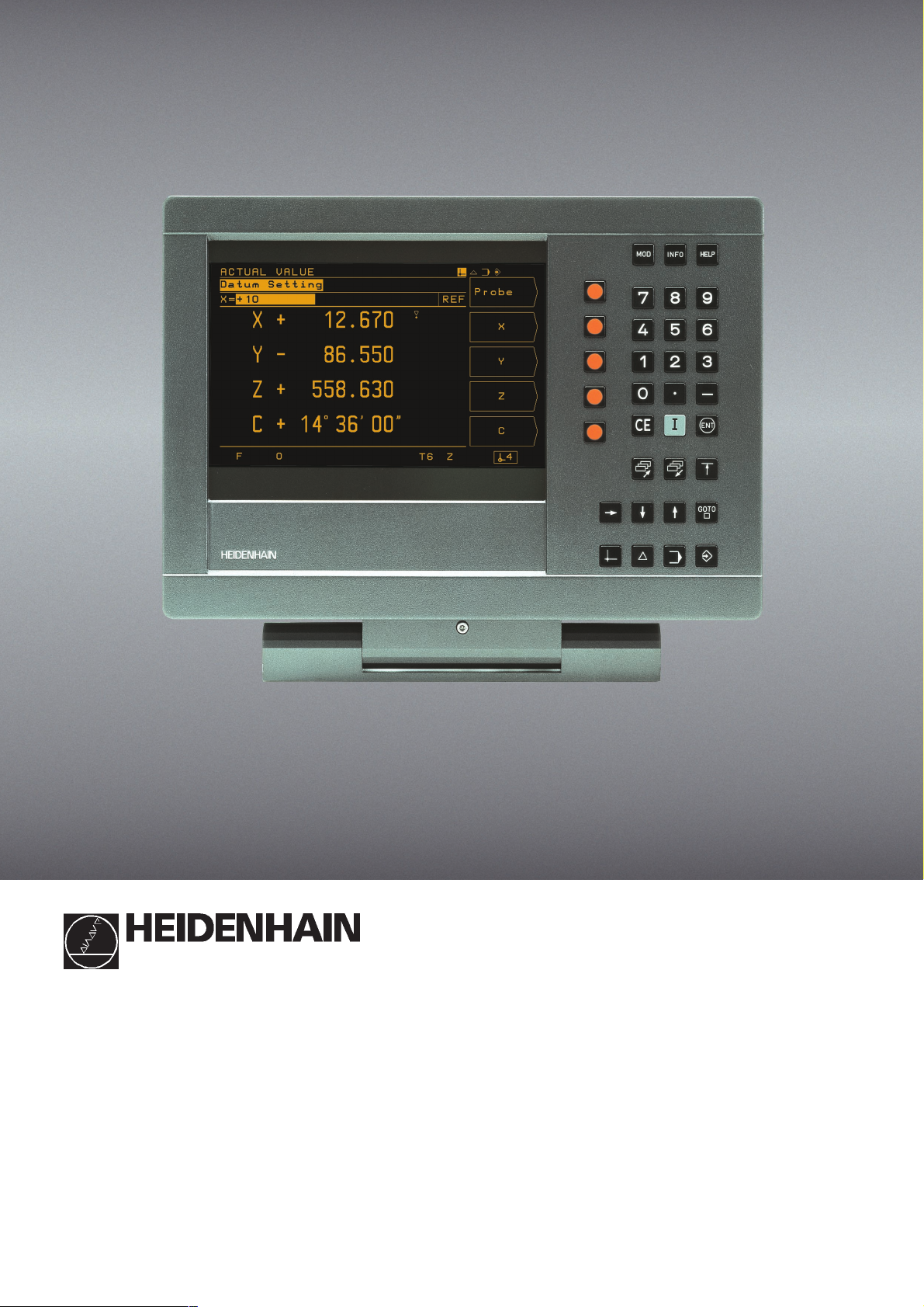
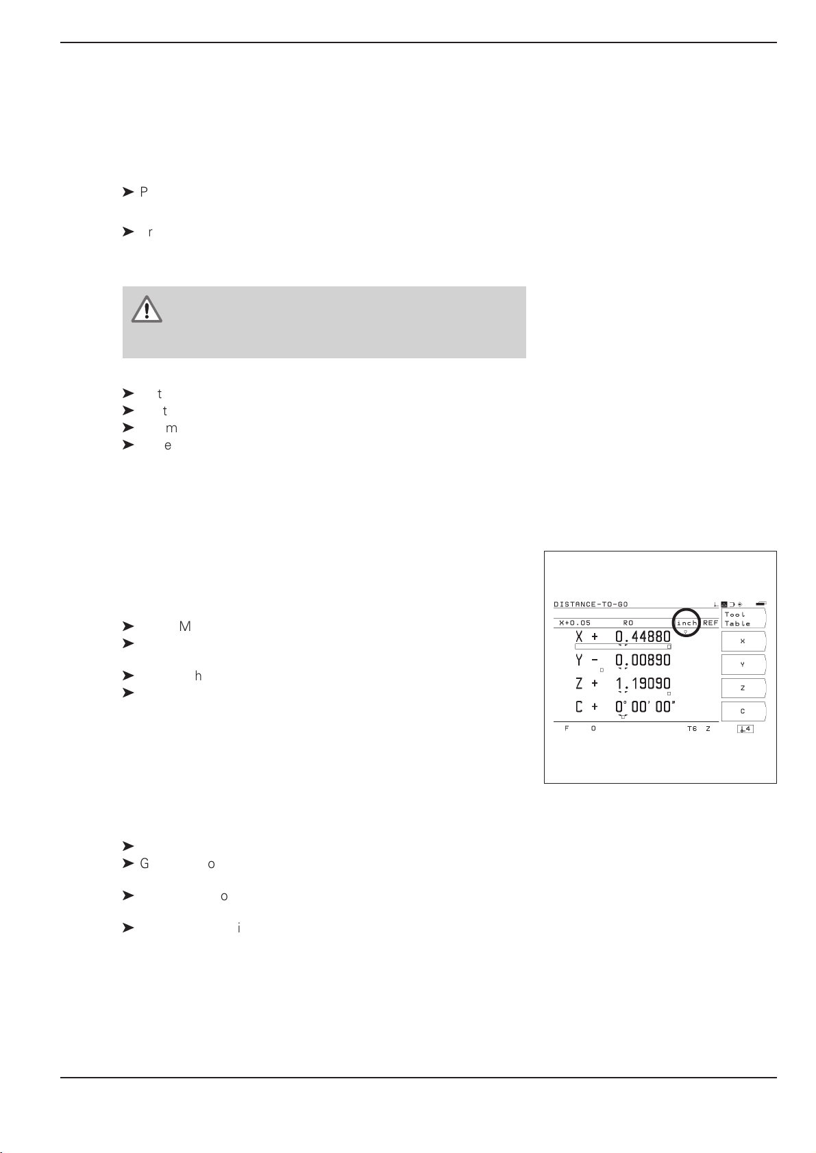
Screen
Plain language
dialog line
Input line
Distance-to-go
display
Feed rate
Operating
mode or
function
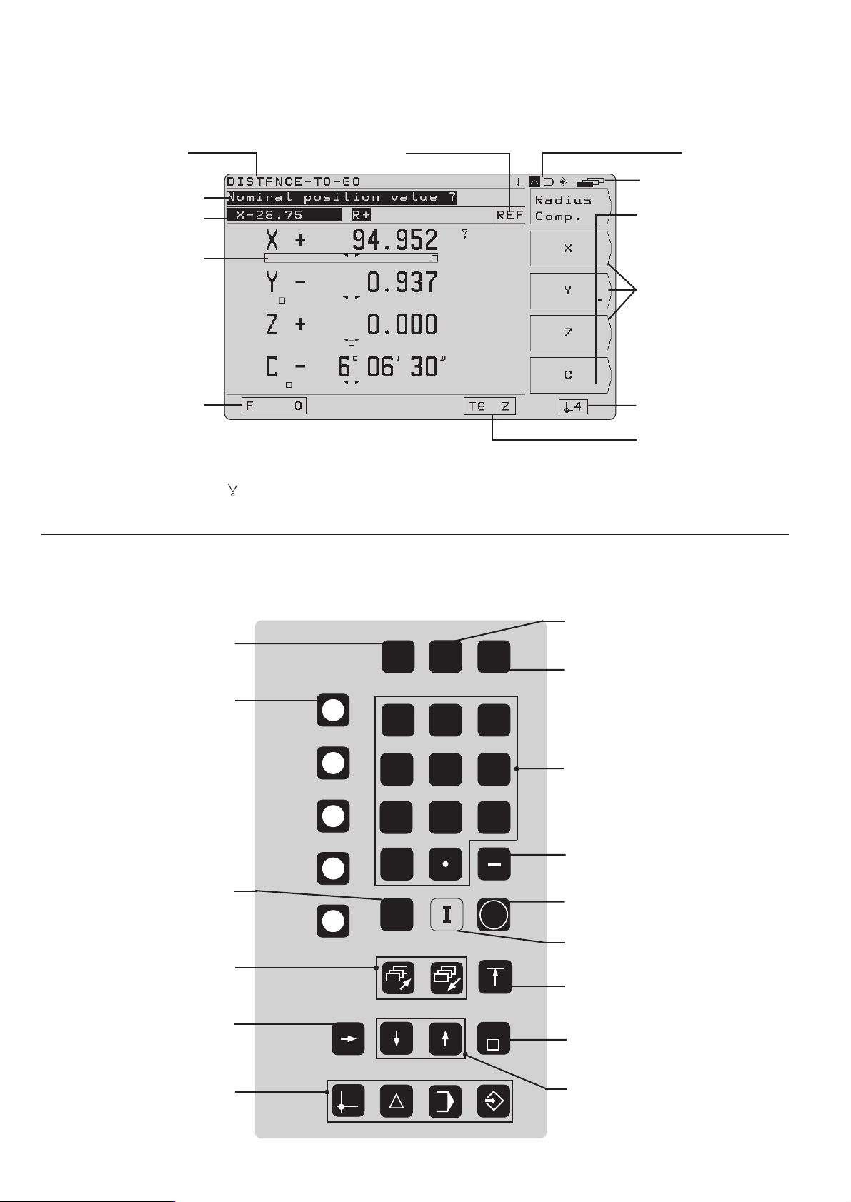
Symbols
Behind the position display:
: Scaling factor or oversize active
Æ: Diameter display
Reference marks
have been
crossed over
Operating mode
symbols (current
mode is highlighted)
Symbol for
soft-key row
Soft-key row
(with 5 soft
keys)
Soft keys
Datum
Tool number
and tool axis
Keyboard
Change parameters
and settings
5 soft keys
(functions vary accord-
ing to associated fields
on screen)
Clear entries or
error messages
Page through
individual screens
Access program blocks to
make changes, or switch
operating parameters
MOD
7
4
1
0
CE
INFO
8
5
2
HELP
9
6
3
ENT
GOTO
Select or deselect
INFO functions
Select or deselect HELP
screens
Numeric input keys
Change sign
Confirm entry
Incremental
dimensions
Return to previous
soft-key row
Go to program block or
operating parameter
Select operating mode
Switch datum;
select entry fields
Page 3

Software version
This User's Manual is for POSITIP models with the following software version:
The x's can be any numbers. The software version of your unit is
shown on a label on the rear panel.
This User's Manual covers the functions of the
POSITIP 855 for milling applications. For turning
applications, a separate manual is available.
Location for use
This unit corresponds to class A in accordance with EN 55 022 and
will be used predominantly in industrially zoned areas
About this manual
This manual is divided into two parts:
Part I: Operating Instructions ... starts on page 5
Part II: Technical Information ..... starts on page 81
246 xxx-05.
Operating Instructions
When using the POSITIP in your work, you need only refer to the
Operating Instructions (Part I).
If you're new to POSITIP, you can use the operating instructions
as a step-by-step workbook. This part begins with a short introduction to the basics of coordinate systems and position feedback,
and provides an overview of the available features. Each feature is
explained in detail, using an example which you can immediately
try out on the machine so you won't get "lost" in the theory. As a
beginner you should work through all the examples presented.
If you're already familiar with POSITIP, you can use the operating
instructions as a comprehensive review and reference guide. The
clear layout and the subject index make it easy to find the desired
topics.
Technical Information
If you are interfacing POSITIP to a machine or wish to use the data
interfaces, refer to the technical information in Part II.
Subject Index
A subject index for both parts of the manual can be found on
pages 113 to 115.
POSITIP 855 Operating Instructions
Page 4

Page 5
Dialog flowcharts
Dialog flowcharts are used for each example in this manual.
They are laid out as follows:
This area shows the
keys to press.
This area explains the key function or work step.
If necessary, supplementary information will also be included.
Prompt
This area shows the
keys to press.
A prompt appears with some actions (not always) at the top of
the screen. In the flowcharts the prompts always have a gray
background.
If two flowcharts are divided by a broken line, this means that you
can follow the instructions either above or below the broken line.
Some flowcharts also show the screen that will appear after you
press the correct keys.
Abbreviated flowcharts
Abbreviated flowcharts supplement the examples and explanations. An arrow ( ➤ ) indicates a new input or a work step.
This area explains the key function or work step.
If necessary, supplementary information will also be included.
If there is an arrow at the end of the flowchart, this means that it continues on
the next page.
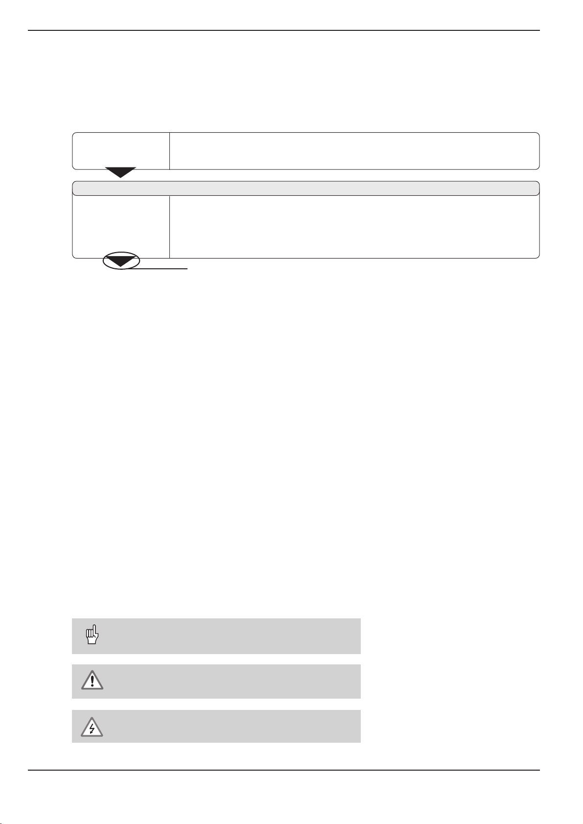
Important Notes in this Manual
The surfaces marked gray contain especially important information.
Please pay special attention to these notes.
Neglecting this information can result in e.g. functions not working
in the desired way or in causing damage to the workpiece or to the
tool.
Symbols within the notes
Every note is marked with a symbol on the left informing about the
meaning of the note.
General Information,
e.g. on the behaviour of the POSITIP.
Important Information,
e.g. when a special tool is required for a function.
Electric Shock Warning,
e.g. when opening a housing.
Operating Instructions POSITIP 855
Page 6

Page 7

Part I: Operating Instructions
I - 1 Fundamentals of Positioning ......................................................7
I - 2 Working with POSITIP First Steps .........................................13
Before you start ................................................................................................ 13
Switch-on ......................................................................................................... 13
Operating modes .............................................................................................. 14
The HELP, MOD and INFO functions ................................................................ 14
Selecting soft-key functions .............................................................................. 15
On-screen operating instructions....................................................................... 16
Error messages ................................................................................................ 17
Selecting the unit of measurement ................................................................... 17
Selecting the angle format ................................................................................ 17
Entering tool length and diameter...................................................................... 18
Calling the tool data .......................................................................................... 19
Datum setting: Approaching positions and entering actual values ..................... 20
Probing functions for datum setting................................................................... 22
Displaying and moving to positions ................................................................... 29
I - 3 Hole Patterns and Rectangular Pocket ....................................35
Bolt hole circle patterns .................................................................................... 35
Linear hole patterns .......................................................................................... 39
Milling a rectangular pocket .............................................................................. 43
I
I - 4 Programming POSITIP ..............................................................45
PROGRAMMING AND EDITING operating mode .............................................. 45
Program number ............................................................................................... 46
Deleting programs ............................................................................................. 46
Editing programs ............................................................................................... 47
Entering program blocks ................................................................................... 48
Calling the tool data in a program...................................................................... 50
Calling datum points ......................................................................................... 50
Transferring positions: Teach-In mode .............................................................. 51
Hole patterns in programs ................................................................................. 56
Rectangular pocket milling in programs ............................................................ 60
Entering program interruptions .......................................................................... 63
Subprograms and program section repeats ....................................................... 64
Editing program blocks ..................................................................................... 69
Deleting program blocks ................................................................................... 70
Transferring programs over the data interface ................................................... 71
I - 5 Executing Programs ..................................................................73
I - 6 The INFO Functions:
Pocket Calculator, Stopwatch and Cutting Data Calculator ..75
To access the INFO functions ........................................................................... 75
Cutting data: Calculate spindle speed S and feed rate F.................................... 76
Stopwatch ........................................................................................................ 77
Pocket calculator functions ............................................................................... 77
I - 7 User Parameters: The MOD Function ......................................79
Scaling factors .................................................................................................. 79
Entering user parameters .................................................................................. 80
Part II: Technical Information............................................................ 81
Subject Index....................................................................................113
Operating Instructions
Page 8

Page 9
I - 1 Fundamentals of Positioning
0° 90°90°
0°
30°
30°
60°
60°
Greenwich
+X
+Y
+Z
+X
+Z
+Y
Fundamentals of Positioning
I-1
Fundamentals of Positioning
You can skip over this chapter if you are familiar with the
concepts of coordinate systems, incremental and absolute
dimensions, nominal and actual positions, and distance-to-go.
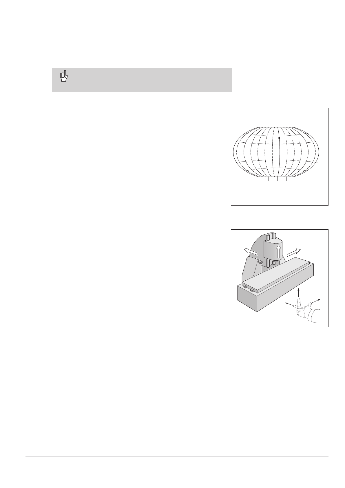
Coordinate systems
In order to define positions on a surface, a reference system is
required. For example, positions on the earth's surface can be
defined absolutely by their geographic coordinates of longitude and
latitude. The term coordinate comes from the Latin word for "that
which is arranged." In contrast to the relative definition of a position that is referenced to a known location, the network of horizontal and vertical lines on the globe constitute an absolute reference
system.
On a milling machine equipped with a position display unit, workpieces are normally machined according to a workpiece-based Cartesian coordinate system (a rectangular coordinate system named
after the French mathematician and philosopher Renatus Cartesius,
who lived from 1596 to 1650). The Cartesian coordinate system is
based on three coordinate axes designated X, Y and Z which are
parallel to the machine guideways.
The figure to the right illustrates the "right-hand rule" for remembering the three axis directions: the middle finger is pointing in the positive direction of the tool axis from the workpiece toward the tool (the
Z axis), the thumb is pointing in the positive X direction, and the index finger in the positive Y direction.
Fig. 1: The geographic coordinate system is an
absolute reference system
Fig. 2: Designations and directions of the axes
on a milling machine
POSITIP 855 Operating Instructions 7
Page 10
I - 1 Fundamentals of Positioning
Y
X
Z
Fundamentals of Positioning
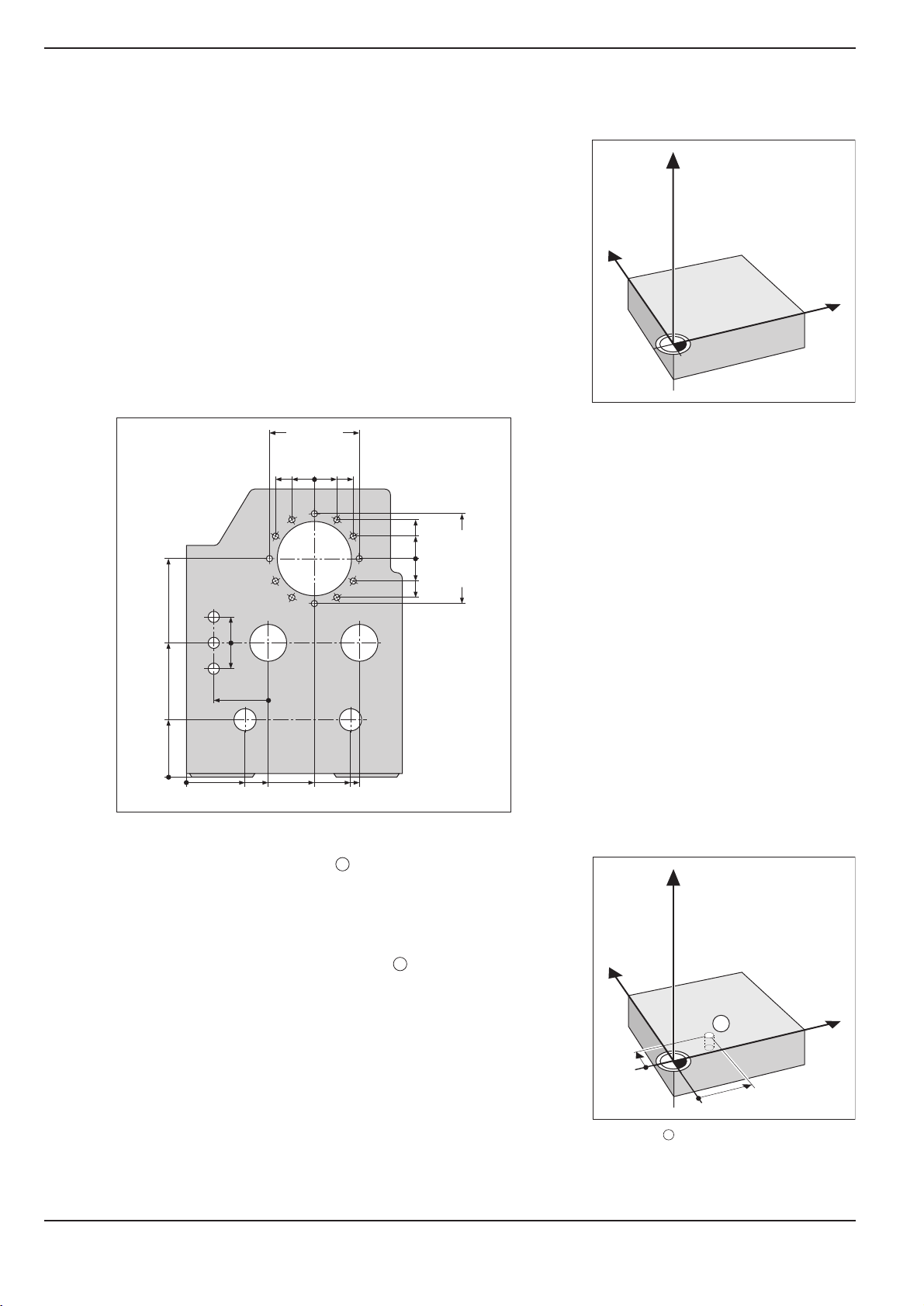
Setting the datum
The workpiece drawing identifies a certain point on the workpiece
(usually a corner) as the absolute datum and perhaps one or
more other points as relative datums. The datum setting procedure
establishes these points as the origin of the absolute or relative coordinate systems: The workpiece, which is aligned with the machine axes, is moved to a certain position relative to the tool and
the display is set either to zero or to another appropriate value
(e.g., to compensate the tool radius).
Example:Drawing with several relative datums
(ISO 129 or DIN 406 Part 11, fig. 171)
125
250
216,5
-250
-125
-216,5
0
Fig. 3: The workpiece datum represents the
origin of the Cartesian coordinate
system
250
-250
Z
1225
150
0
0
-150
300±0,1
325
0
450
700
1
750
320
0
Example: Coordinates of hole :
X = 10 mm
900
216,5
125
0
-125
-216,5
950
Y = 5 mm
Z = 0 mm (hole depth: Z = 5 mm)
The datum of the Cartesian coordinate system
is located 10 mm from hole in the X axis and
1
Y
5 mm from it in the Y axis (in negative direction).
The KT Edge Finder from HEIDENHAIN, together with the
POSITIP'S edge finding functions, facilitates finding and setting
1
X
datums.
5
10
Fig. 4: Hole defines the coordinate system
1
8 Operating Instructions POSITIP 855
Page 11
I - 1 Fundamentals of Positioning
Y
X
Z
I
S
R
Y
X
Z
1
20
10
Z=15mm
X=20mm
Y=10mm
15
IZ=–15mm
Y
X
Z
2
10
5
5
15
20
10
10
I
X=10mm
I
Y=10mm
3
0
0
R
Fundamentals of Positioning
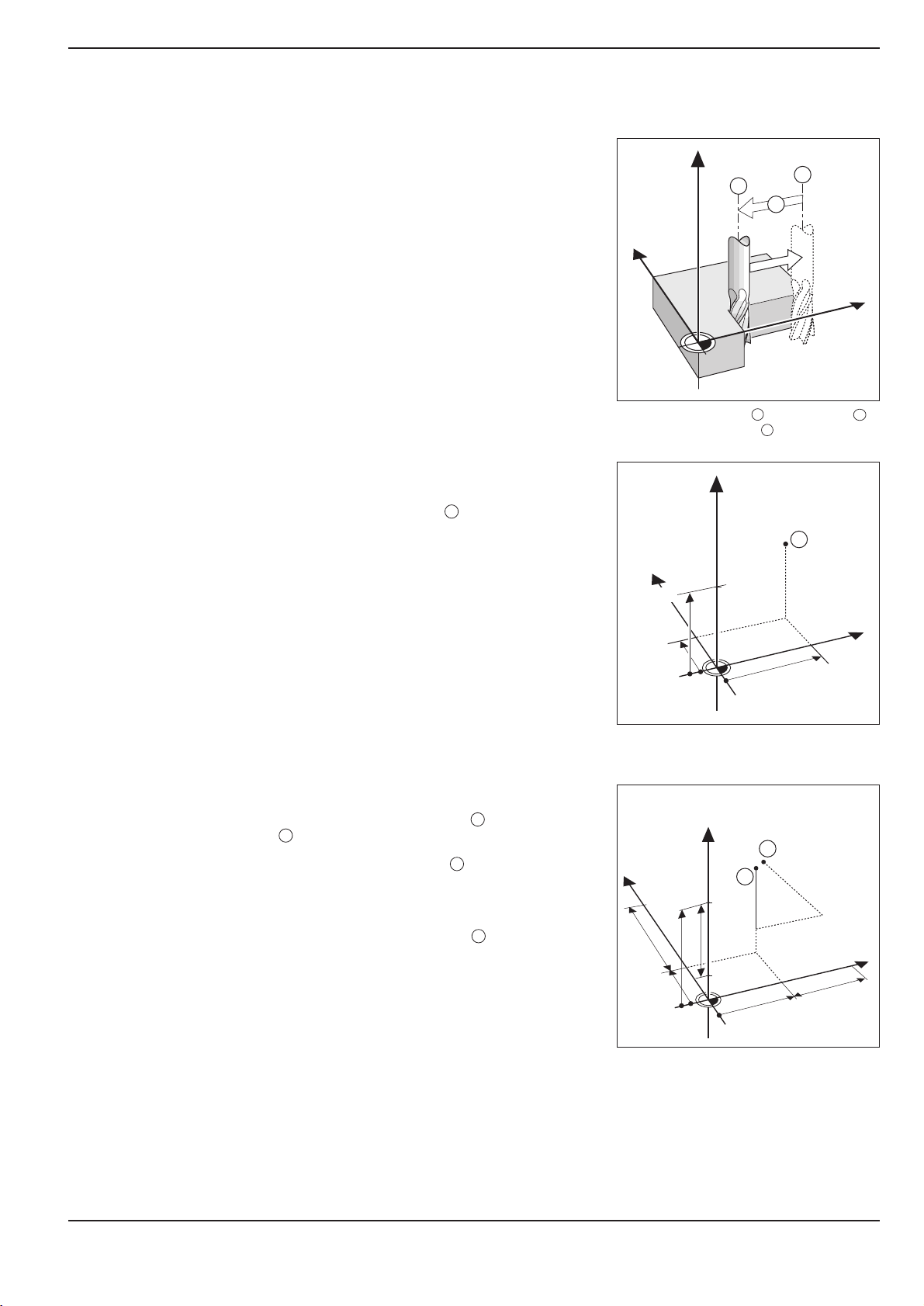
Nominal position, actual position and distance-to-go
The position that the tool is to move to is called the nominal posi-
tion, while the position of the tool at any given moment is called
the actual position. The distance from the nominal position to the
actual position is called the distance-to-go.
Sign for distance-to-go
The distance-to-go has a positive sign if the axis direction from the
actual towards the nominal position is negative.
The distance-to-go has a negative sign if the axis direction from the
actual towards the nominal position is positive.
Fig. 5: Nominal position , actual position
and distance-to-go
S
I
Absolute workpiece positions
Each position on the workpiece is uniquely identified by its absolute
coordinates.
Example: Absolute coordinates of position :
1
X= 20 mm
Y= 10 mm
Z= 15 mm
If you are drilling or milling a workpiece according to a workpiece
drawing with absolute coordinates, you are moving the tool to the
value of the coordinates.
Incremental workpiece positions
A position can also be referenced to the preceding nominal position. In this case the relative datum is always the last programmed
position. Such coordinates are referred to as incremental coordi-
nates (increment = increase). They are also called incremental or
chain dimensions (since the positions are defined as a chain of di-
Fig. 6: Position definition through absolute
coordinates
mensions). Incremental coordinates are designated with the
prefix
I.
Example: Incremental coordinates of position referenced to
position
2
Absolute coordinates of position :
3
2
X= 10 mm
Y = 5 mm
Z= 20 mm
Incremental coordinates of position :
3
IX= 10 mm
IY= 10 mm
IZ= 15 mm
If you are drilling or milling a workpiece according to a drawing
with incremental coordinates, you are moving the tool by the value
of the coordinates.
POSITIP 855 Operating Instructions 9
An incremental position definition is therefore a specifically relative
definition. Likewise, a position defined by the distance-to-go to
the nominal position is also a relative position (in this case the relative datum is in the nominal position).
Fig. 7: Position definition through incremental
coordinates
Page 12
I - 1 Fundamentals of Positioning
Fundamentals of Positioning
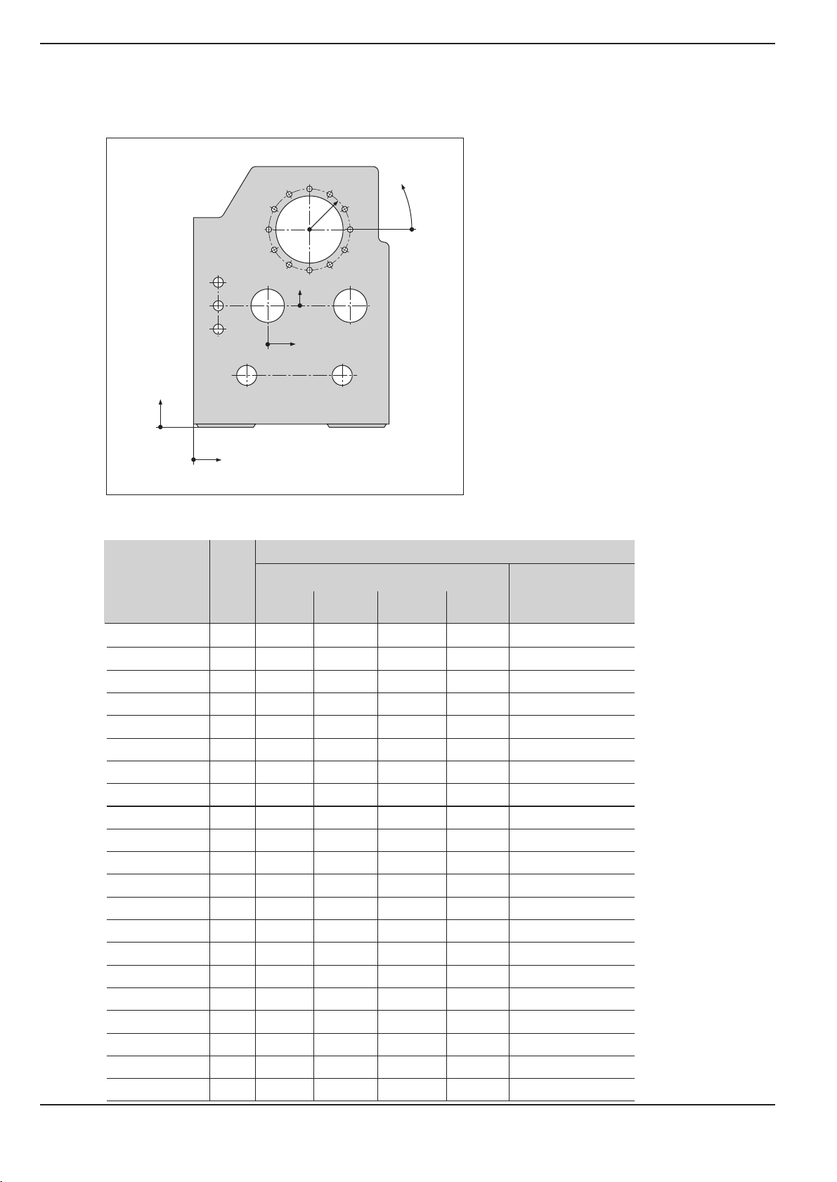
Example: Workpiece drawing with coordinate dimensioning (ISO 129 or DIN 406 part 11, fig. 179)
3.4
3
3.10
Y2
X2
3.3
3.2
r
3.1
3.12
3.11
1.21.1
ϕ
Y1
3.5
3.6
3.7
3.8
2.1
2.2
2.3
1
3.9
2 1.3
X1
A coordinate list corresponding to this example is useful when
working in the PROGRAMMING AND EDITING operating mode.
Dimensions in mm
Coordinates
Coordinate
origin
Pos. X1 X2 Y1 Y2 r j d
1100
1 1.1 325 320 Æ 120 H7
1 1.2 900 320 Æ 120 H7
1 1.3 950 750 Æ 200 H7
1 2 450 750 Æ 200 H7
1 3 700 1225 Æ 400 H8
2 2.1 300 150 Æ 50 H11
2 2.2 300 0 Æ 50 H11
2 2.3 300 150 Æ 50 H11
3 3.1 250 0° Æ 26
3 3.2 250 30° Æ 26
3 3.3 250 60° Æ 26
3 3.4 250 90° Æ 26
3 3.5 250 120° Æ 26
3 3.6 250 150° Æ 26
3 3.7 250 180° Æ 26
3 3.8 250 210° Æ 26
3 3.9 250 240° Æ 26
3 3.10 250 270° Æ 26
3 3.11 250 300° Æ 26
3 3.12 250 330° Æ 26
10 Operating Instructions POSITIP 855
Page 13
I - 1 Fundamentals of Positioning
Y
X
Z
Y
X
+45°
+180°
–180°
–270°
Fundamentals of Positioning
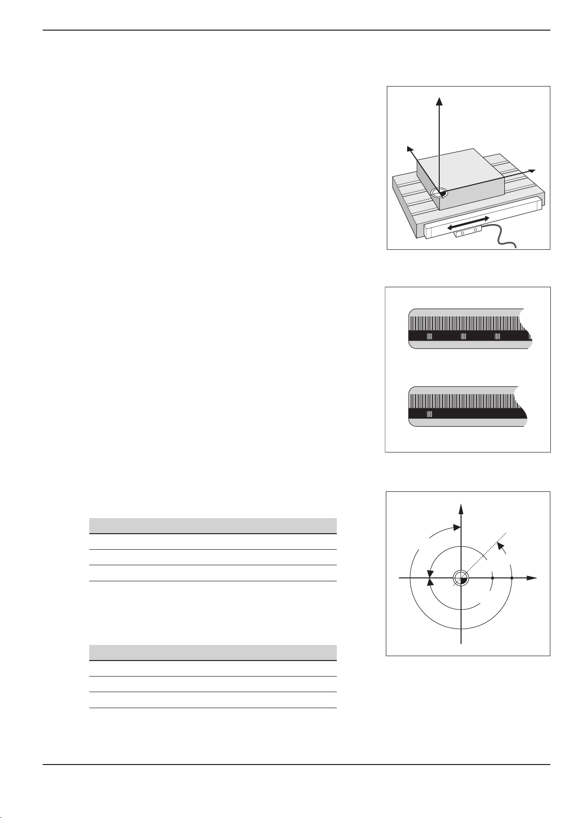
Position feedback
The position feedback encoders convert the movement of the machine axes into electrical signals. The POSITIP constantly evaluates
these signals and calculates the actual positions of the machine
axes, which it displays as a numerical value on the screen.
If there is an interruption in power, the calculated position will no
longer correspond to the actual position. When power is restored,
you can re-establish this relationship with the aid of the reference
marks on the position encoders and the POSITIP's reference mark
evaluation feature (REF).
Reference marks
The scales of the position encoders contain one or more reference
marks. When a reference mark is passed over, it generates a signal
which identifies that position as the reference point (scale reference
point = machine reference point). With the aid of this reference
mark the POSITIP's REF feature re-establishes the assignment of
displayed positions to machine axis positions which you last defined by setting the datum.
Fig. 8: Linear position encoder, here for the X
axis
Angle reference axis
If the position encoders feature distance-coded reference marks,
each axis needs only move a maximum of 20 mm (0.8 in.) for linear
encoders, and 20° for angle encoders.
For angular positions, the following reference axes are defined:
Plane Angle reference axis
X Y +X
Y Z +Y
Z X +Z
Positive direction of rotation is counterclockwise if the working
plane is viewed in negative tool axis direction (see fig. 10).
Example: Angle in the working plane X / Y
Angle Corresponds to the...
+ 45° ... bisecting line between +X and +Y
+/ 180° ... negative X axis
270° ... positive Y axis
Fig. 9: Linear scales: with distance-coded ref-
erence marks (upper illustration) and
one reference mark (lower illustration)
Fig. 10: Angle and the angle reference axis, e.g.
in the X / Y plane
POSITIP 855 Operating Instructions 11
Page 14

I - 1 Fundamentals of Positioning
Fundamentals of Positioning
NOTES
12 Operating Instructions POSITIP 855
Page 15
I - 2 Working with POSITIP First Steps
I-2
Working with POSITIP First Steps
Before you start
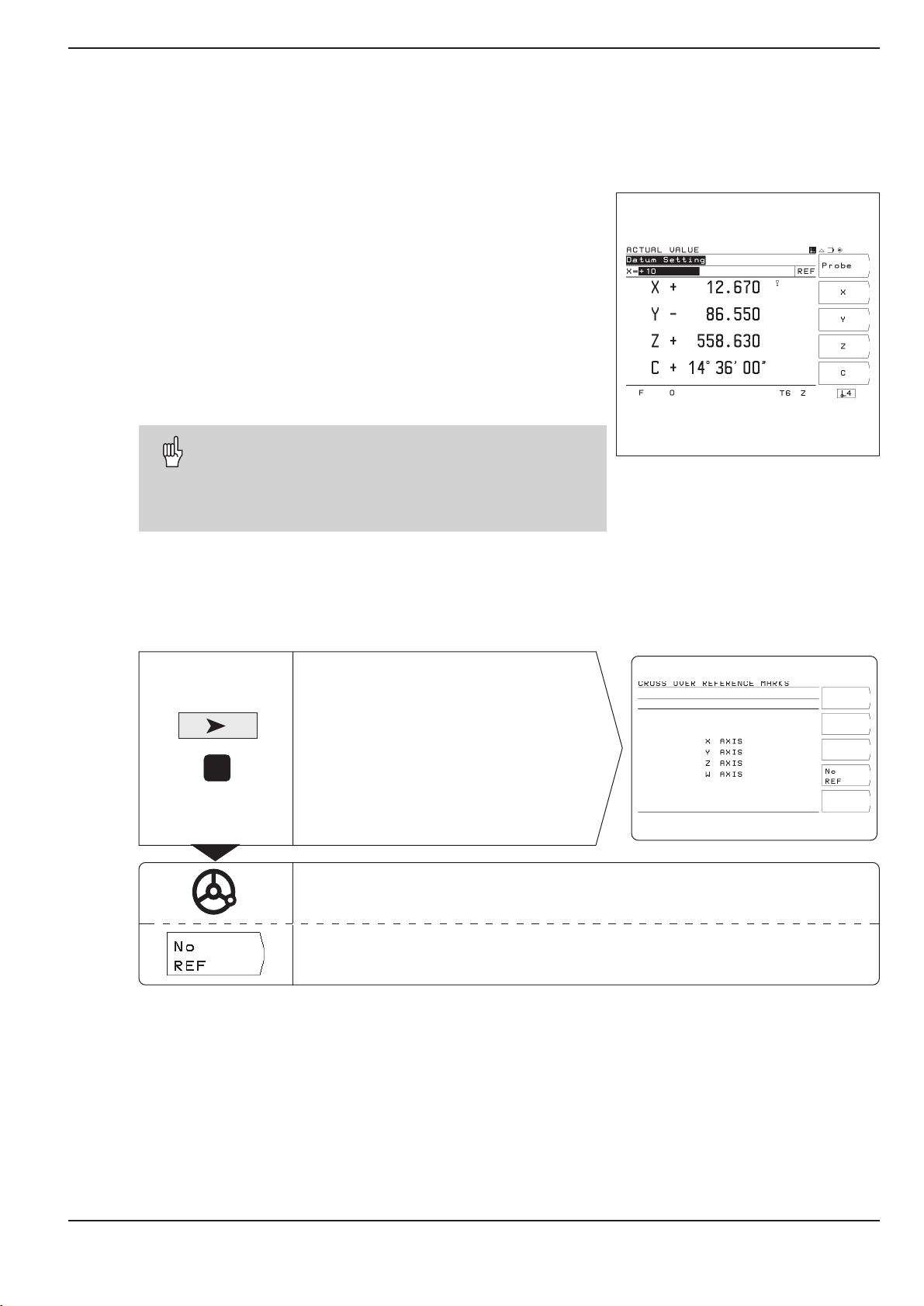
You can cross over the reference marks after every switch-on.
The POSITIP's reference mark evaluation feature (REF) automati-
cally re-establishes the relationship between axis slide positions
and display values that you last defined by setting the datum.
When you have crossed over all the reference marks, the REF
indicator appears in the input line at the top of the screen.
Setting new datum points automatically stores the new relationship between axis positions and display values.
Working without reference mark evaluation
You can also use the POSITIP without crossing over the reference
marks simply press the soft key No REF.
Note that if you do not cross over the reference marks,
POSITIP does not store the datum points. This means
that it is not possible to re-establish the relationship
between axis slide positions and display values after a
power interruption (switch-off).
Fig. 11: REF display on screen
Switch-on
Your POSITIP is now ready for operation and is in the ACTUAL VALUE operating mode.
0
ä
1
Switch on the power
and
press any key.
Cross over the reference marks in all axes
(in any order).
Do not cross over the reference marks.
Note: In this case the relationship between axis slide positions and
display values will be lost after a power interruption.
POSITIP 855 Operating Instructions 13
Page 16
I - 2 Working with POSITIP First Steps
Operating modes
Selecting the operating mode determines which functions are available to you.
Available functions Mode Key
Position display for ACTUAL VALUE
workpiece machining;
Zero reset;
Datum setting
also with edge finder
Distance-to-go display; hole DISTANCE-
patterns; rectangular pocket; TO-GO
drilling and milling with tool radius compensation
Storage of work steps for PROGRAMMING
small-lot production AND EDITING
Run programs previously EXECUTE
created in the PROGRAMMING PROGRAM
AND EDITING mode
You can switch to another operating mode at any time by
pressing the key for the desired mode.
The HELP, MOD and INFO functions
You can call the HELP, MOD and INFO functions at any time.
To call a function:
ä
Press the function key for that function.
To leave the function:
ä
Press the same function key again.
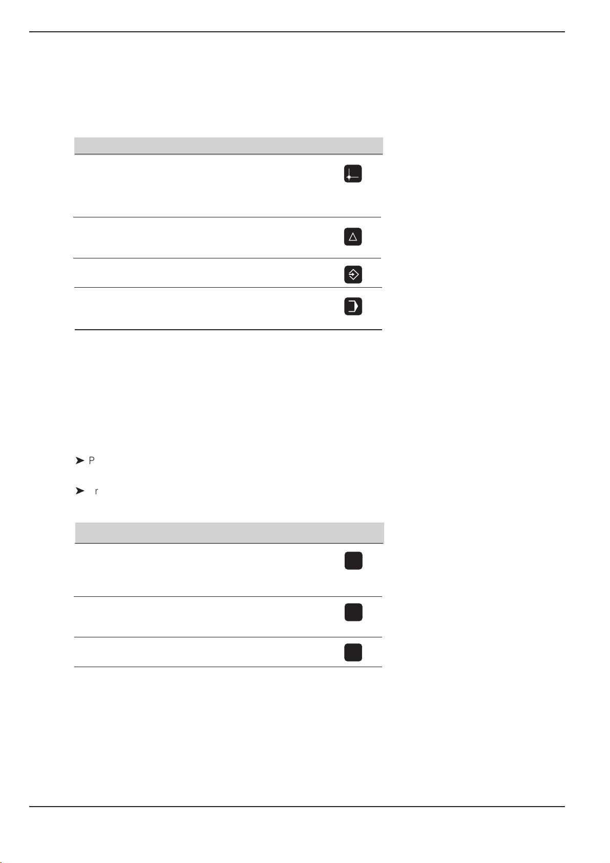
Available functions Mode Key
On-screen operating HELP
instructions: graphics and
text keyed to the current
screen contents
User parameters: MOD
To redefine POSITIP's basic
operating characteristics
HELP
MOD
Cutting data calculator, INFO
stopwatch, pocket calculator
INFO
14 Operating Instructions POSITIP 855
Page 17
I - 2 Working with POSITIP First Steps
Selecting soft-key functions
The soft-key functions are grouped into one or more rows.
POSITIP indicates the number of rows by a symbol at the upper
right of the screen. If no symbol is shown, that means there is only
one row for the function. The highlighted rectangle in the symbol
indicates the current row.
Function Key
Page throught soft-key rows: forwards
Page through soft-key rows: backwards
Go back one level
POSITIP displays the soft keys with the main functions of an operating mode whenever you press the
key for that mode.
Fig. 12: The symbol for soft-key row is at the
top right of the screen. Here, the second row is being displayed.
POSITIP 855 Operating Instructions 15
Page 18
I - 2 Working with POSITIP First Steps
On-screen operating instructions
The integrated operating instructions provide information and assistance in any situation.
To call the operating instructions:
ä
Press the HELP key.
ä
Use the paging keys if the explanation is spread over more than
one screen page.
To leave the operating instructions:
ä
Press the HELP key again.
Example: On-screen operating instructions for datum setting
with the edge finder (PROBE CIRCLE CENTER)
The PROBE CIRCLE CENTER function is described in this manual
on page 25.
ä
Select the ACTUAL VALUE operating mode.
ä
Press the Probe soft key.
➤ Press the HELP key.
The first page of the operating instructions for the Probe function
appears.
Page reference at the lower right of the screen:
the number in front of the slash is the current page, the number
behind the slash is the total number of pages.
The on-screen operating instructions now contains the following
information on ACTUAL VALUE – PROBE (on three pages):
Overview of the probing functions (page 1)
Graphic illustration of all probing functions
(pages 2 and 3)
Fig. 13: On-screen operating instructions for
PROBE CIRCLE CENTER, page 1
ä
To leave the operating instructions:
Press HELP again.
The screen returns to the selection menu for the probing func-
tions.
ä
Press (for example) the soft key Circle Center.
ä
Press HELP.
The screen now displays operating instructions spread over
five pages on the PROBE CIRCLE CENTER function including:
Overview of all work steps (page 1)
Graphic illustration of the probing sequence (page 2)
Information on how POSITIP reacts and on datum setting
(page 3)
Probing function Circle Center for tools (pages 4 and 5)
ä
To leave the on-screen operating instructions:
Press HELP.
Fig. 14: On-screen operating instructions for
PROBE CIRCLE CENTER, page 2
Fig. 15: On-screen operating instructions for
PROBE CIRCLE CENTER, page 3
16 Operating Instructions POSITIP 855
Page 19
I - 2 Working with POSITIP First Steps
Error messages
If an error occurs while you are working with POSITIP, a message
will come up on the screen in plain English.
To call an explanation of the error:
ä
Press the HELP key.
To clear the error message:
ä
Press the CE key.
Blinking error messages
W A R N I N G
Blinking error messages mean that the operational
reliability of the POSITIP has been impaired.
If a blinking error message occurs:
ä
Note down the error message displayed on the screen.
ä
Switch off the power to the POSITIP.
ä
Attempt to correct the problem with the power off.
ä
If the blinking error message recurs, notify your customer
service agency.
Selecting the unit of measurement
Positions can be displayed in millimeters or inches. If you choose
inches, inch will be displayed at the top of the screen next to
REF.
To change the unit of measurement:
ä
Press MOD.
ä
Page to the soft key row containing the user parameter
mm or inch.
ä
Choose the soft key mm or inch to change to the other unit.
ä
Press MOD again.
For more information on user parameters, see chapter I - 7.
Selecting the angle format
Angles such as for a rotary table can be displayed either as a
decimal value or in degrees, minutes and seconds.
To change the angle format:
ä
Press MOD.
ä
Go to the soft key row containing the user parameter
Deg/Min/Sec or Degrees decimal.
ä
Choose the soft key Deg/Min/Sec or degrees decimal
to change to the other format.
ä
Press MOD again.
Fig. 16: The inch indicator
For more information on user parameters, see chapter I - 7.
POSITIP 855 Operating Instructions 17
Page 20
I - 2 Working with POSITIP First Steps
Z
X
∆L3<0
∆L
2
>0
∆L
1
=0
D
1
T
1
T
2
T
3
D
2
D
3
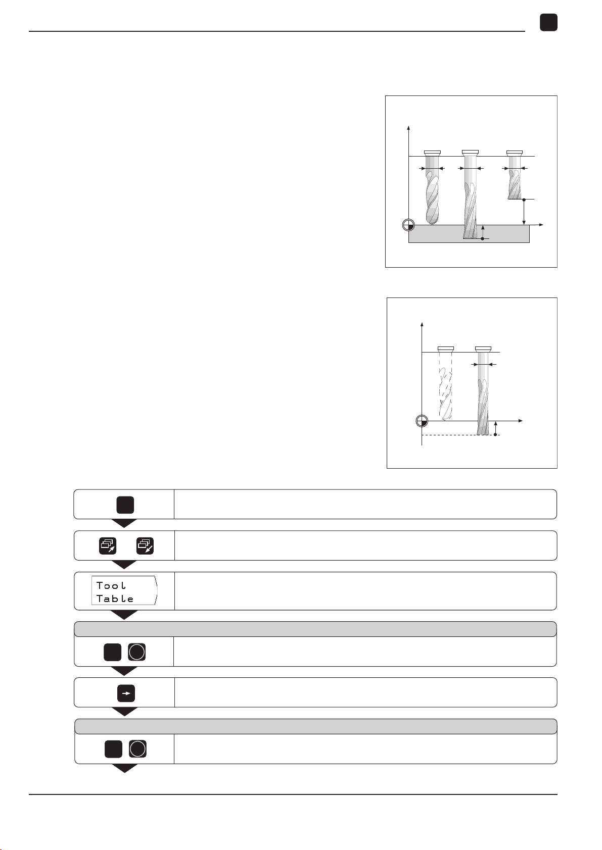
Entering tool length and diameter
Enter the lengths and diameters of your tools in the POSITIP's tool
table. You can enter up to 99 tools.
Before you start machining workpieces, select the tool you are using from the tool table. POSITIP will then take into account the entered diameter and length of the tool.
The tool length is the difference in length DL between the tool and
the zero tool.
Sign for the length difference DL
If the tool is longer than the zero tool: DL > 0
If the tool is shorter than the zero tool: DL < 0
Example: Entering the tool length and diameter into the tool table
Tool number 7
Tool axis Z
Tool diameter D = 8 mm
Fig. 17: Tool length and diameter
Z
T
0
T
7
D
7
MOD
Tool length L = 12 mm
MOD
/
Select the user parameters.
Go to the soft key row which has Tool Table.
Open the tool table.
Tool number ?
ENT
7
Enter the tool number (such as 7) and confirm your entry with ENT.
=0
L
0
X
L7>0
18 Operating Instructions POSITIP 855
Tool diameter ?
ENT
8
Go to the column with Diameter.
Enter the tool diameter (such as 8 mm) and confirm your entry with ENT.
Page 21
I - 2 Working with POSITIP First Steps
Tool length ?
MOD
2
1
MOD
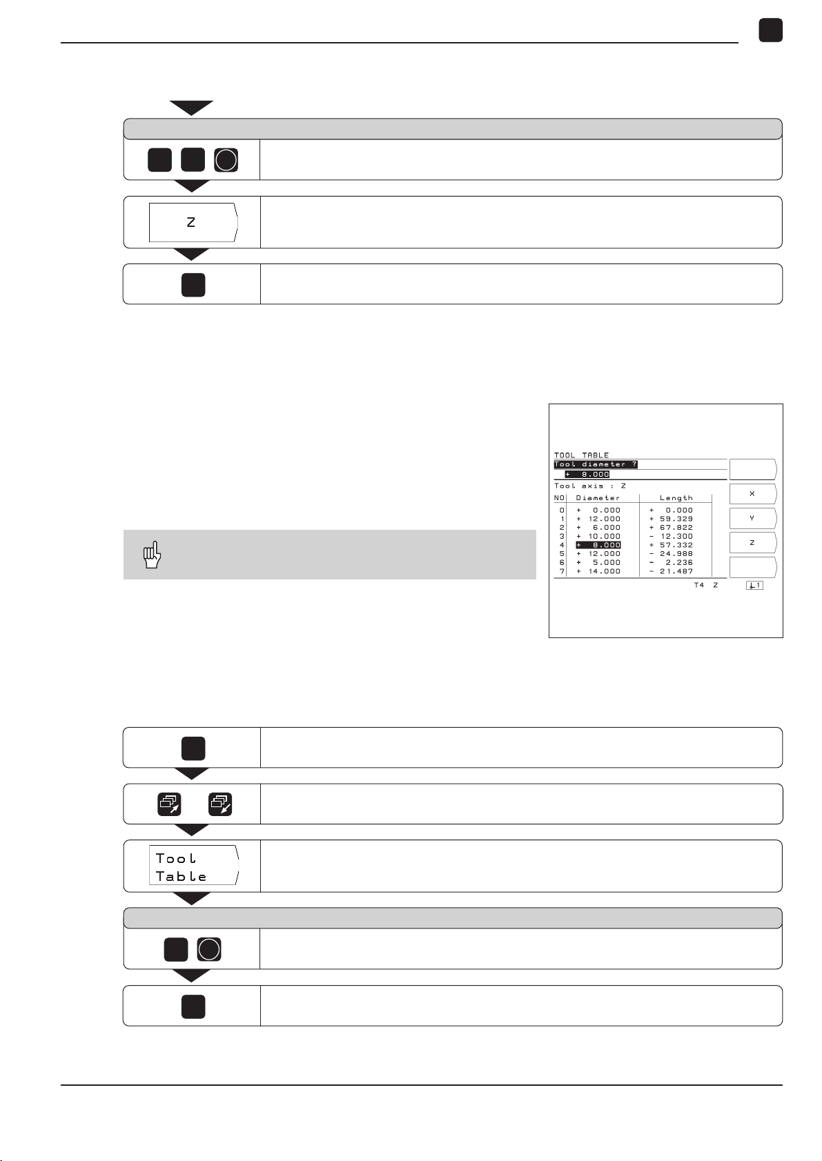
Calling the tool data
The lengths and diameters of your tools must first be entered into
the POSITIP's tool table (see previous page).
Before you start workpiece machining, select the tool you are using from the tool table. POSITIP then takes into account the stored
tool data when you work with tool compensation (e.g., with hole
patterns).
You can also call the tool data with the command
TOOL CALL in a program.
ENT
Enter the tool length (12 mm) and confirm your entry with ENT.
Select the tool axis (Z).
Depart the user parameters.
Calling the tool data
MOD
5
MOD
Select the user parameters.
/
Go to the first soft key row which has Tool Table.
Select the tool table.
Tool number ?
ENT
Enter the tool number (here: 5) and confirm your entry with ENT.
The number of the selected tool appears at the bottom of the screen.
Depart the user parameters.
Fig. 18: The tool table on the POSITIP's screen
POSITIP 855 Operating Instructions 19
Page 22
I - 2 Working with POSITIP First Steps
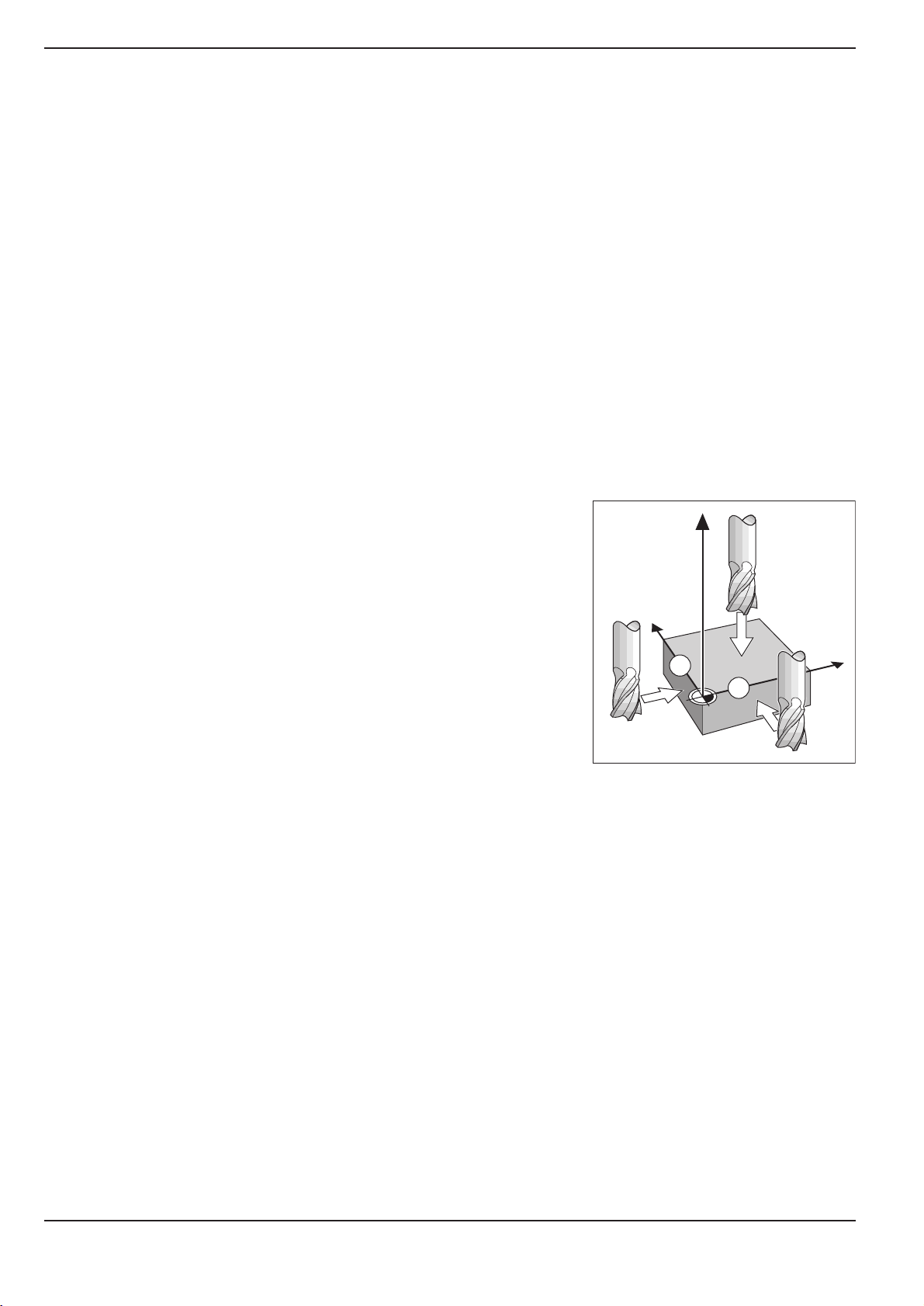
Datum setting: Approaching positions and entering actual values
The easiest way to set datum points is to use the POSITIP's probing functions regardless of whether you probe the workpiece with
the HEIDENHAIN KT Edge Finder or with a tool. A description of the
probing functions starts on page 22.
Of course, you can also set datum points in the conventional manner by touching the edges of the workpiece one after the other with
the tool and entering the tool positions as datum points (see examples on this page and the next).
The datum table can hold up to 99 datum points. In most cases this
will free you from having to calculate the axis travel when working
with complicated workpiece drawings containing several datums.
For each datum point, the datum table contains the positions that
the POSITIP assigned to the reference points on the scales (REF
values) during datum setting. Note that if you change the REF values in the table, this will move the datum point.
Example: Setting a workpiece datum without the probing function
Working plane: X / Y
Tool axis: Z
Tool radius: R = 5 mm
Axis sequence in
this example: X - Y - Z
Preparation: Select the datum
Select the datum with the vertical arrow keys.
POSITIP displays the number of the current datum at the lower right
of the screen.
Preparation: Call the tool data
Call the tool data for the tool which you are using to touch the workpiece (see previous page).
Z
Y
X
1
2
20 Operating Instructions POSITIP 855
Page 23
I - 2 Working with POSITIP First Steps
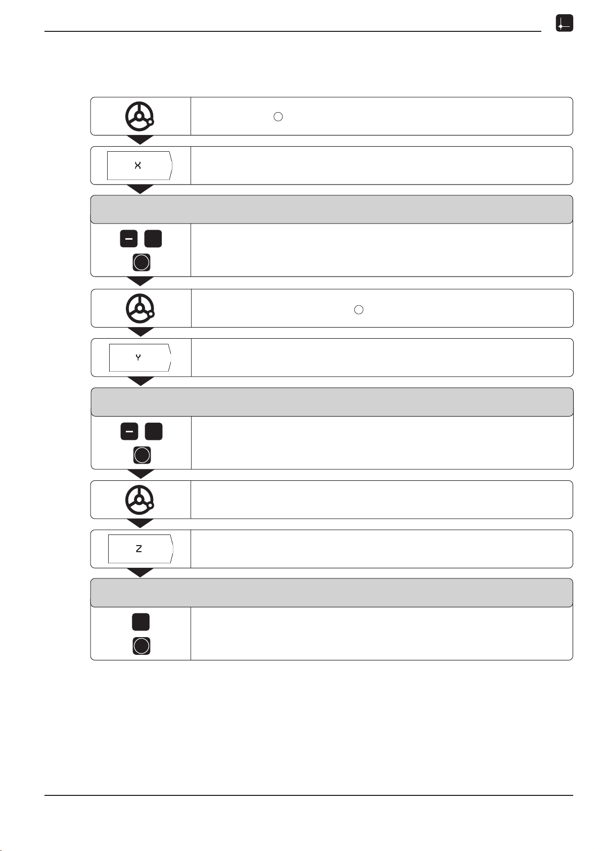
Datum setting: Approaching positions and entering actual values
Operating mode: ACTUAL VALUE
Touch edge with the tool.
Select the X axis.
Datum Setting
X = + 0
5
ENT
Enter the position of the tool center (X = 5 mm)
and
transfer the X coordinate of the datum.
Touch the workpiece at edge .
Select the Y axis.
Datum Setting
Y = + 0
1
2
5
ENT
Enter the position of the tool center (Y = 5 mm)
and
transfer the Y coordinate of the datum.
Touch the workpiece surface.
Select the Z axis.
Datum Setting
Z = + 0
0
ENT
Enter the position of the tool tip (Z = 0 mm)
and
transfer the Z coordinate of the datum.
POSITIP 855 Operating Instructions 21
Page 24
I - 2 Working with POSITIP First Steps
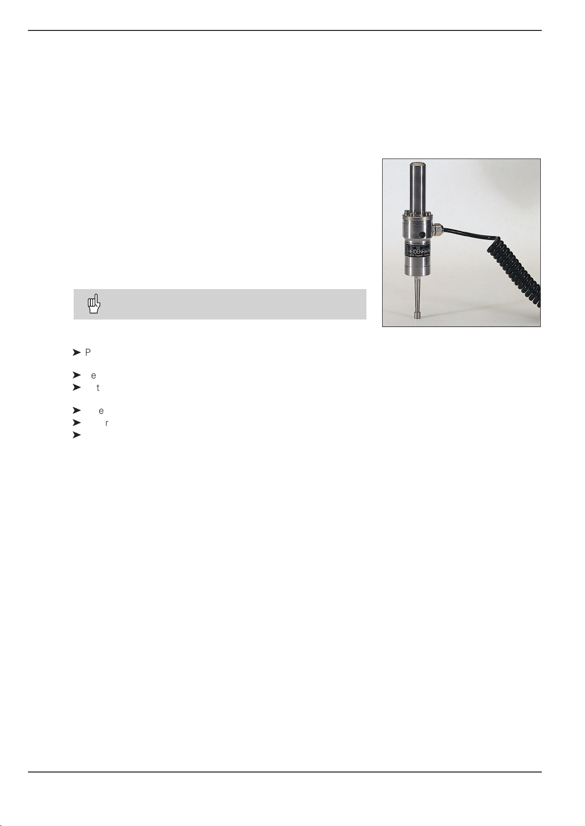
Probing functions for datum setting
The POSITIP's probing functions enable you to set datum points
with a HEIDENHAIN KT Edge Finder. The probing functions are
also available when you are using a tool instead of an edge finder.
Datum setting with the edge finder
It is particularly easy to set datum points with a HEIDENHAIN
KT Edge Finder. The following probing functions are available:
Workpiece edge as datum:
Edge
Centerline between two workpiece edges:
Centerline
Center of a hole or cylinder:
Circle Center
With Circle Center, the hole must be in a main plane.
The three main planes are formed by the axes X / Y, Y / Z
and Z / X.
The HEIDENHAIN KT 120 Edge Finder can only be
used with electrically conductive workpieces.
Preparation: Enter the stylus diameter and select the datum
ä
Press MOD and go to the soft key row containing the soft key
Edge Finder.
ä
Select the user parameter Edge Finder.
ä
Enter the diameter of the edge finder stylus and confirm with
ENT.
ä
Select the user parameter Datum.
ä
Enter the number of the desired datum and confirm with ENT.
ä
Press MOD again.
The number of the selected datum is now shown at the lower
right of the screen.
In all probing functions, POSITIP takes into account the entered
stylus diameter.
For more information on user parameters, see chapter I - 7.
Exiting the probing function
While the probing function is active, POSITIP displays the soft key
Escape. Choose this soft key to return to the opening state of the
selected probing function.
Fig. 19: The HEIDENHAIN KT Edge Finder
22 Operating Instructions POSITIP 855
Page 25
I - 2 Working with POSITIP First Steps
Y
X
Z
X?
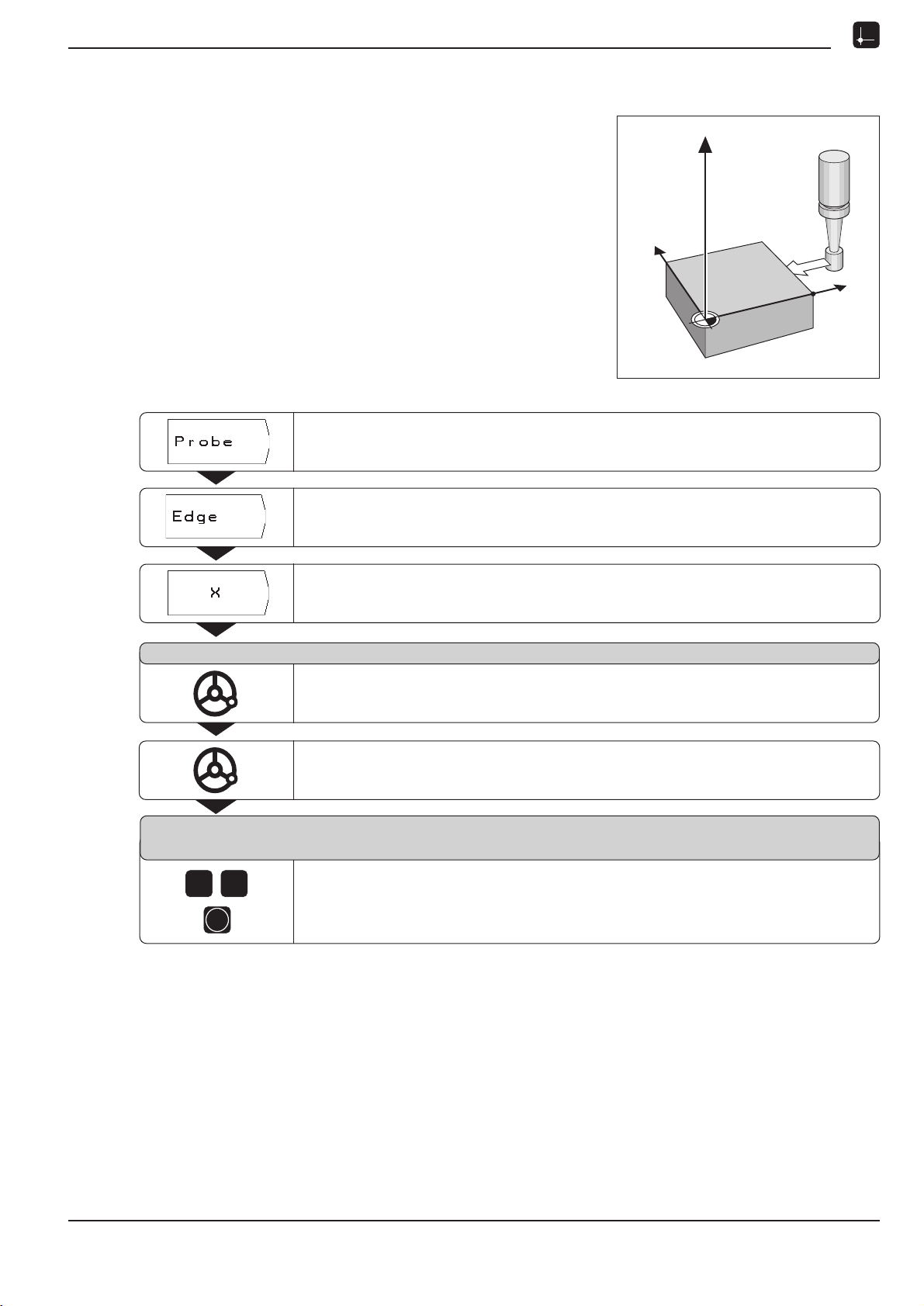
Probing functions for datum setting
Example: Probe workpiece edge, display position of workpiece
edge and set the edge as a datum
The probed edge lies parallel to the Y axis.
The coordinates of the datum can be set by probing edges or sur-
faces and capturing them as datums as described on the next
page.
Operating mode: ACTUAL VALUE
Select Probe.
Select Edge.
Select axis for which the coordinate is to be set: X axis.
Probe in X axis
Move the edge finder towards the workpiece edge until the
LEDs on the edge finder light up.
The position of the edge on the X axis is displayed on the screen.
Retract the edge finder from the workpiece.
Enter value for X
+ 0
2
0
ENT
0 is offered as a default value for the coordinate.
Enter the desired coordinate for the workpiece edge, for example X = 20 mm
and
set the coordinate as a datum for this workpiece edge.
POSITIP 855 Operating Instructions 23
Page 26
I - 2 Working with POSITIP First Steps
Probing functions for datum setting
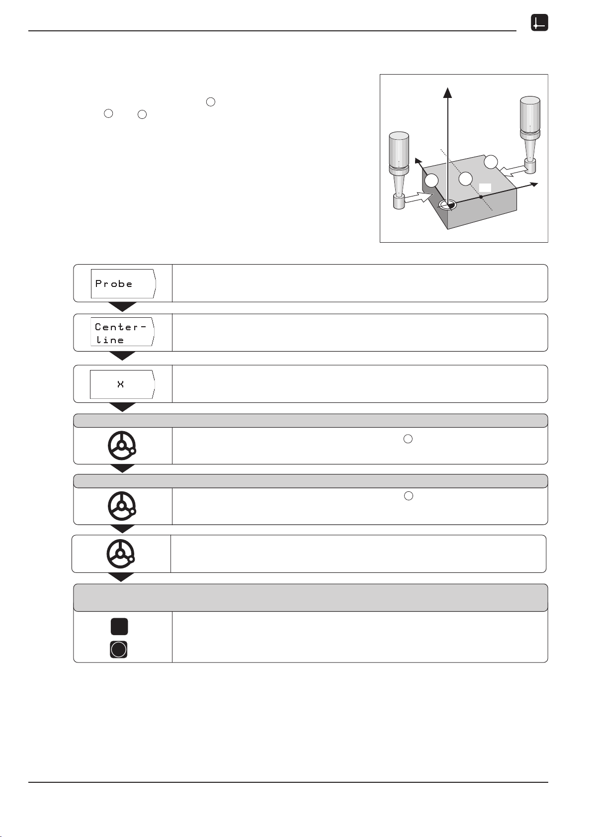
Example:Set centerline between two workpiece edges as datum
The position of the centerline is determined by probing the
edges and .
1
2
M
The centerline is parallel to the Y axis.
Desired coordinate
of the centerline: X = 5 mm
Operating mode: ACTUAL VALUE
Select Probe.
Z
Y
2
1
M
X?
X
Select Centerline.
Select the axis for which the coordinate is to be set: X axis.
Probe 1st edge in X
Move the edge finder toward workpiece edge until the LEDs in the
edge finder light up.
Probe 2nd edge in X
Move the edge finder toward workpiece edge until the LEDs in the
edge finder light up. The display is frozen and the distance between the
two edges appears under the selected axis.
Retract the edge finder from the workpiece.
Enter value for X
+ 0
1
2
5
Enter coordinate (X = 5 mm)
and
ENT
transfer coordinate as datum for the centerline.
24 Operating Instructions POSITIP 855
Page 27
I - 2 Working with POSITIP First Steps
Y
X
0
1
2
3 4
X?
Probing functions for datum setting
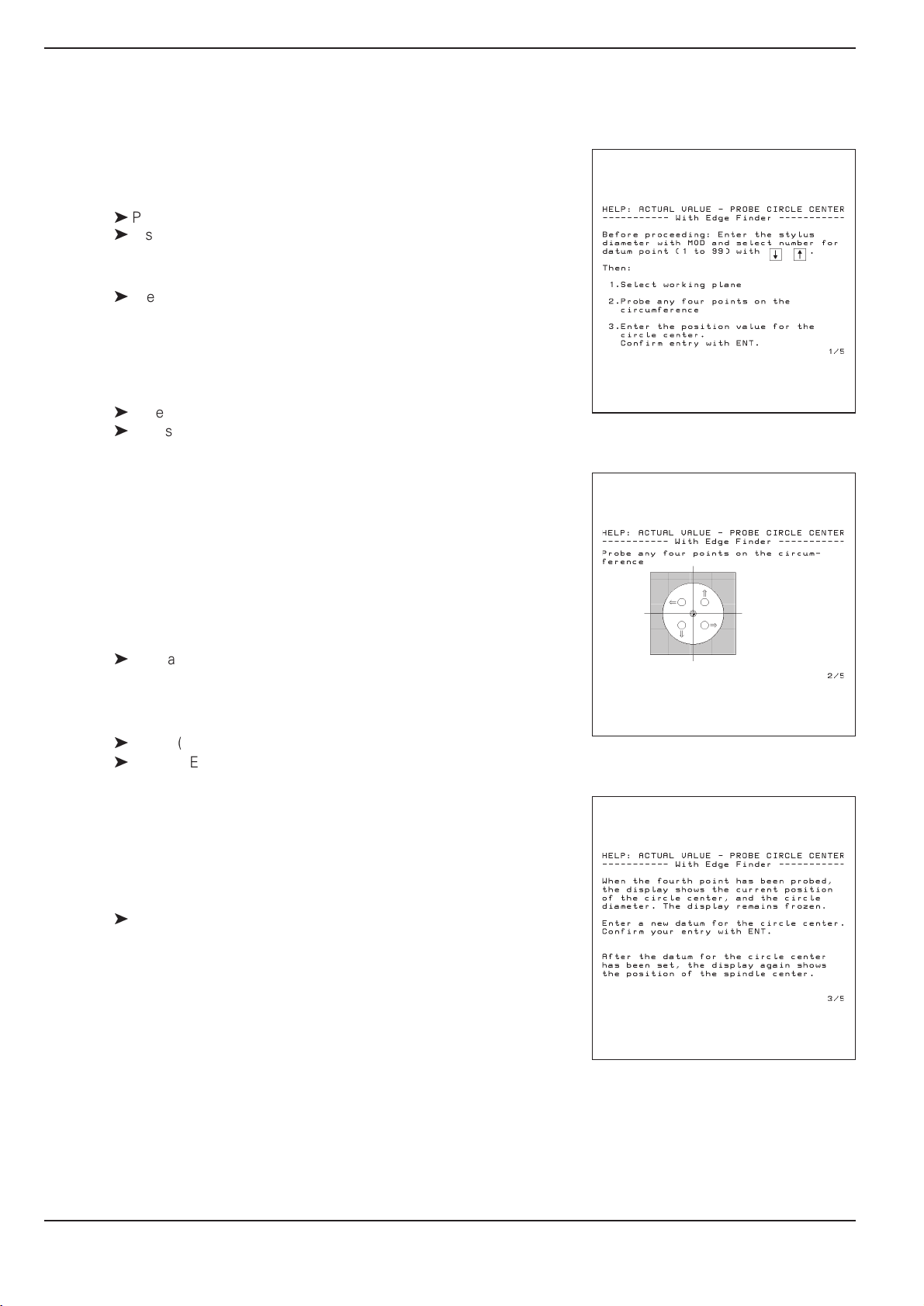
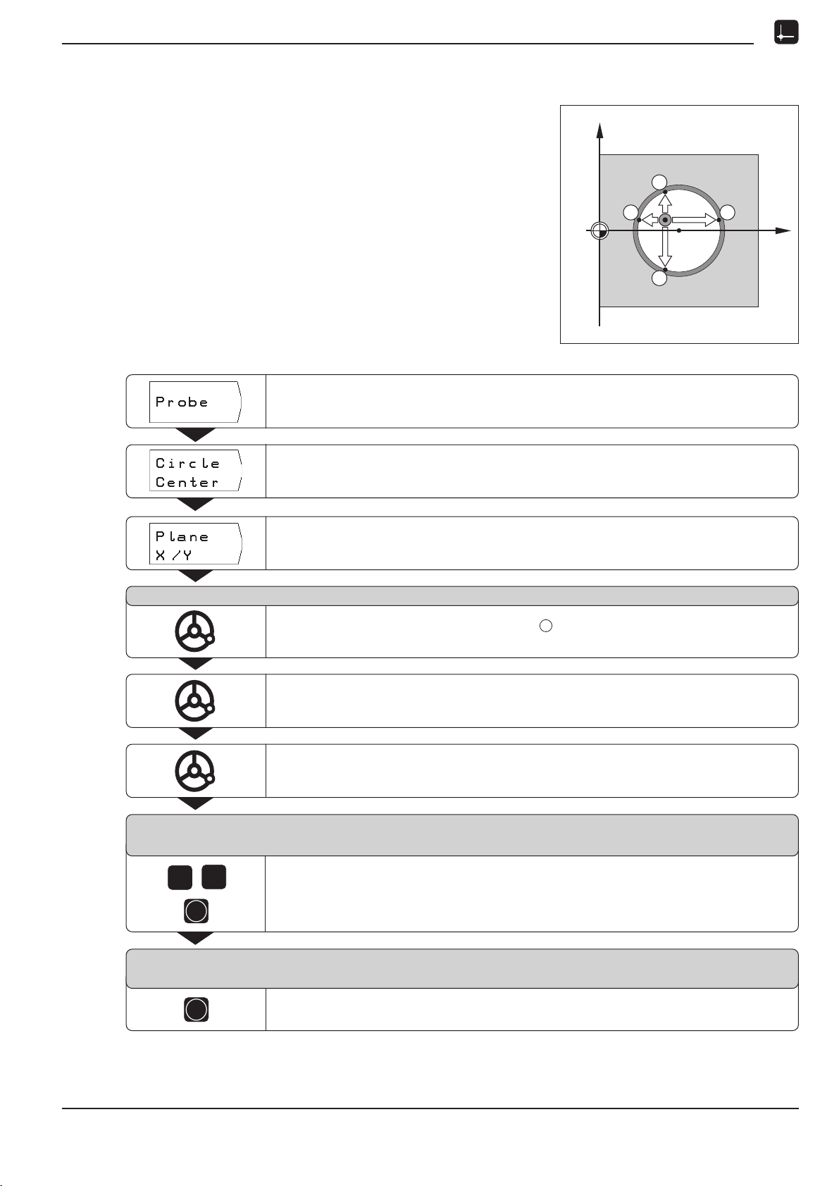
Example: Probe the circumference of a hole with an edge finder
and set the center of the hole as a datum
Main plane X / Y
Edge finder axis parallel to the Z axis
X coordinate of the
circle center X = 50 mm
Y coordinate of the
circle center Y = 0 mm
Operating mode: ACTUAL VALUE
Select Probe.
Select Circle Center.
Select plane containing the circle (main plane): Plane X/Y.
Probe 1st point in X/Y
Move edge finder towards first point on the circumference until the LEDs
on the edge finder light up.
Retract edge finder from bore hole wall.
Probe three additional points on the circumference in the same manner.
Further instructions appear on the screen.
Enter center point X
X = 0
0
5
ENT
Enter the first coordinate (X = 50 mm)
and
transfer coordinate as datum for the circle center.
1
POSITIP 855 Operating Instructions 25
Y = 0
ENT
Accept default entry Y = 0 mm.
Enter center point Y
Page 28
I - 2 Working with POSITIP First Steps
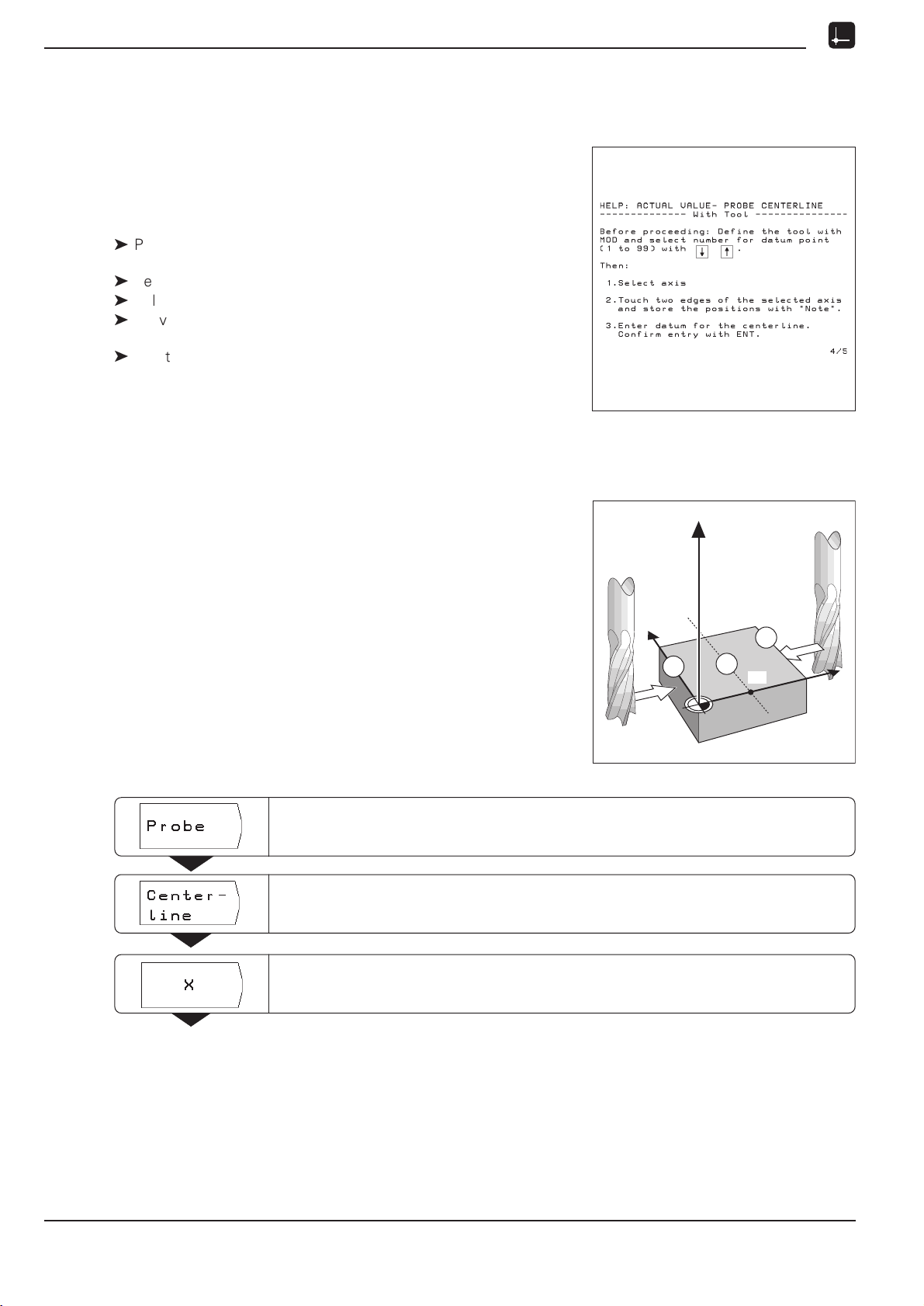
Probing functions for datum setting
Datum setting with a tool
Even if you use a tool to set datum points, you can still use
POSITIP's probing functions described under the section "Datum
setting with the edge finder" (Edge, Centerline and Circle
Center).
Preparation: Enter the tool diameter and select the datum
ä
Press MOD and go to the soft key row containing the
soft key Tool Table.
ä
Select the user parameter Tool Table.
ä
Select the tool you will use to set the datum.
ä
Leave the tool table:
Press MOD again.
ä
Use the vertical arrow keys to select the number of the desired
datum. The number of the selected datum is shown at the lower
right of the screen.
Fig. 20: On-screen operating instructions for
probing with a tool
Example: Set centerline between two probed edges as datum
The centerline is parallel to the Y axis.
Desired coordinate
of the centerline: X = 50 mm
Operating mode: ACTUAL VALUE
Select Probe.
Select Centerline.
Z
Y
2
1
M
X?
X
Select axis for which the coordinate is to be set: X axis.
26 Operating Instructions POSITIP 855
Page 29
I - 2 Working with POSITIP First Steps
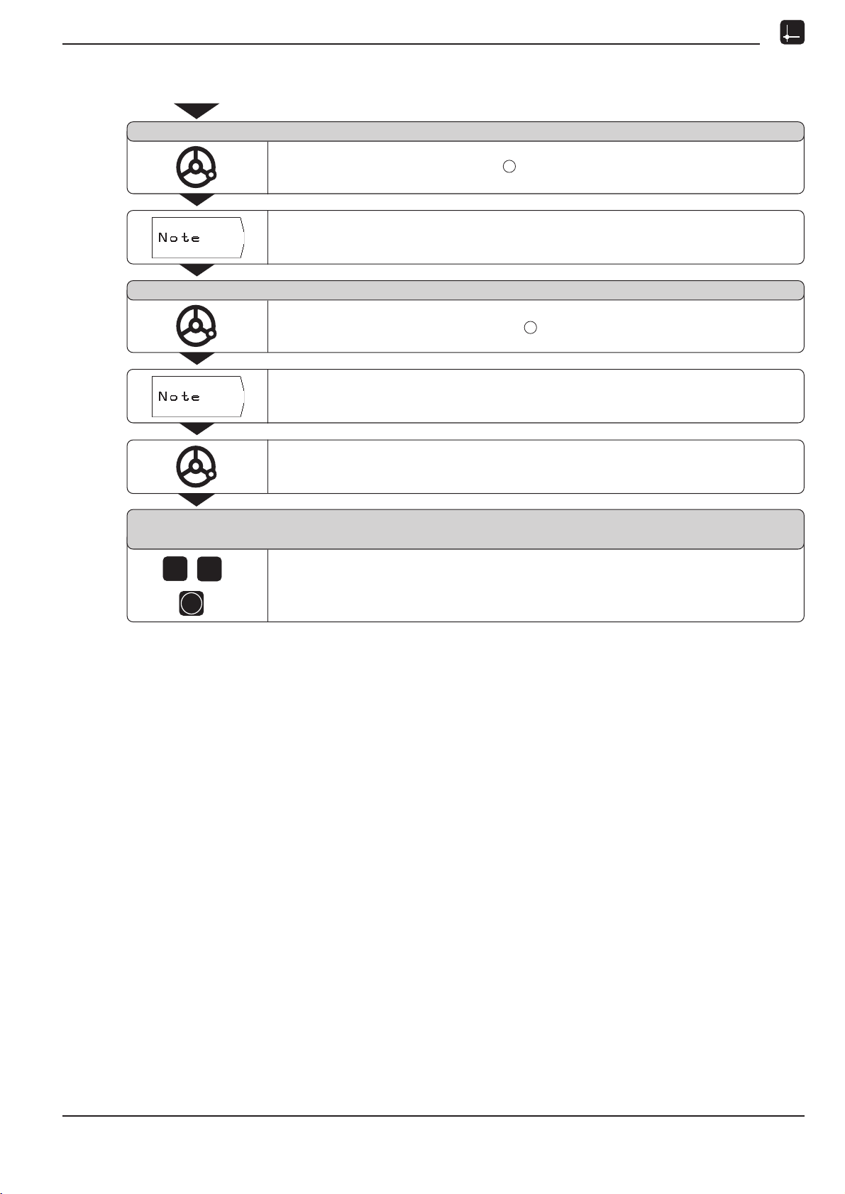
Probing functions for datum setting
Probe 1st edge in X
Touch the first workpiece edge .
Store the position of the edge.
Probe 2nd edge in X
Touch the second workpiece edge .
Store the position of the edge.
POSITIP displays the distance between the two edges.
Retract the tool from the workpiece.
Enter value for X
+ 0
5
0
ENT
Enter coordinate (X = 50 mm)
and
transfer coordinate as datum for the centerline.
1
2
POSITIP 855 Operating Instructions 27
Page 30

I - 2 Working with POSITIP First Steps
NOTES
28 Operating Instructions POSITIP 855
Page 31

I - 2 Working with POSITIP First Steps
R–
R+
Y
X
R
0
Displaying and moving to positions
Distance-To-Go feature
Although it is often sufficient to have POSITIP display the coordinates of the actual position of the tool, it is usually better to use
the Distance-To-Go feature this enables you to approach nomi-
nal positions simply by traversing to display value zero.
Even when working with the Distance-To-Go feature you can enter
coordinates in absolute or incremental dimensions.
Graphic positioning aid
When you are traversing to display value zero, POSITIP displays a
graphic positioning aid (see figure 21).
POSITIP can also show the absolute position instead of
the graphic positioning aid. You can switch between
these two modes with operating parameter P 91 (see
chapter II - 2).
Fig. 21: The graphic positioning aid
POSITIP displays the graphic positioning aid in a narrow rectangle
underneath the currently active axis. Two triangular marks in the
center of the rectangle symbolize the nominal position you want to
reach.
A small square symbolizes the axis slide. An arrow indicating the
direction appears in the square while the axis is moving. You can
thus easily tell whether you are moving towards or away from the
nominal position.
Note that the square does not begin to move until the axis slide is
near the nominal position.
Taking the tool radius into account
POSITIP has a tool radius compensation feature (see figure 22). This
allows you to enter workpiece dimensions directly from the drawing. The displayed remaining distance is then automatically lengthened (R+) or shortened (R) by the value of the tool radius.
Entering tool data
ä
Press MOD.
ä
Choose the soft key Tool Table.
ä
Enter the tool diameter.
ä
Enter the tool length.
ä
Select the tool axis by soft key.
ä
Press ENT.
ä
Press MOD again.
Fig. 22: Tool radius compensation
POSITIP 855 Operating Instructions 29
Page 32

I - 2 Working with POSITIP First Steps
Displaying and moving to positions
Example: Milling a shoulder by traversing to display value zero
The coordinates are entered as absolute dimensions; the datum is
the workpiece zero point.
Corner X = 0 mm Y = 20 mm
Corner X = 30 mm Y = 20 mm
Corner X = 30 mm Y = 50 mm
Corner X = 60 mm Y = 50 mm
1
2
3
4
Preparation:
ä
Enter the tool data.
ä
Pre-position the tool to an appropriate location
(such as X = Y = 20 mm).
ä
Move the tool to milling depth.
Operating mode: DISTANCE-TO-GO
Select the Y axis.
Y
50
20
0
1 2
0
3 4
30
X
60
Nominal position value ?
2
0
Enter nominal position value for corner point : Y = +20 mm
and
select tool radius compensation R +.
ENT
Transfer the nominal position value.
The graphic positioning aid for the Y axis appears.
Traverse the Y axis until the display value is zero.
The square in the graphic positioning aid is now centered
between the two triangular marks.
Select the X axis.
Nominal position value ?
0
3
Enter nominal position value for corner point : X = +30 mm
and
select tool radius compensation R .
1
2
ENT
Transfer the nominal position value.
The graphic positioning aid for the X axis appears.
Traverse the X axis until the display value is zero.
The square in the graphic positioning aid is now centered
between the two triangular marks.
30 Operating Instructions POSITIP 855
Page 33

I - 2 Working with POSITIP First Steps
Displaying and moving to positions
Select the Y axis.
Nominal position value ?
5
0
Enter the nominal position value for corner point : Y = +50 mm
and
select tool radius compensation R +.
3
ENT
Transfer the nominal position value.
The graphic positioning aid for the Y axis is displayed.
Traverse the Y axis until the display value is zero.
The square in the graphic positioning aid is now centered
between the two triangular marks.
Select the X axis.
Nominal position value ?
6
0
ENT
Enter the nominal position value for corner point : X = +60 mm
and
select tool radius compensation R +.
Transfer the nominal position value.
The graphic positioning aid for the X axis is displayed.
Traverse the X axis until the display value is zero.
The square in the graphic positioning aid is now centered
between the two triangular marks.
4
POSITIP 855 Operating Instructions 31
Page 34

I - 2 Working with POSITIP First Steps
Displaying and moving to positions
Example: Drilling by traversing to display value zero
Enter the coordinates in incremental dimensions. These are indicated in the following (and on the screen) with a preceding
The datum is the workpiece zero point.
1
Hole at X = 20 mm
Y=20mm
Distance from hole
to hole
1
2
IX= 30 mm
IY= 30 mm
Hole depth Z =12 mm
Operating mode: DISTANCE-TO-GO
Pre-position the drill over the first hole.
I.
Y
2
50
30
1
20
0
0
20
30
50
X
Select the Z axis.
Nominal position value ?
1 2
ENT
Enter the nominal position value for the hole depth: Z = 12 mm.
Confirm your entry.
The graphic positioning aid for the Z axis is displayed.
Drill hole : traverse Z axis until the display value is zero.
1
The square in the graphic positioning aid is now centered
between the two triangular marks.
Retract the drill in the tool axis (Z).
Select the X axis.
Nominal position value ?
3
0
Enter the nominal position value for hole : X = 30 mm
and
mark your input as an incremental dimension.
2
Select tool radius compensation R 0.
32 Operating Instructions POSITIP 855
Page 35

I - 2 Working with POSITIP First Steps
Displaying and moving to positions
ENT
Confirm your entry.
The graphic positioning aid for the X axis is displayed.
Traverse the X axis until the display value is zero.
The square in the graphic positioning aid is now centered
between the two triangular marks.
Select the Y axis.
ENT
Transfer the displayed nominal position (I +30) directly as nominal value for Y.
The graphic positioning aid for the Y axis is displayed.
Traverse the Y axis until the display value is zero.
The square in the graphic positioning aid is now centered
between the two triangular marks.
Select the Z axis.
Nominal position value ?
1 2
ENT
Enter the nominal position value for the hole depth: Z = 12 mm.
Confirm your entry.
The graphic positioning aid for the Z axis is displayed.
Drill hole : traverse the Z axis until the display value is zero.
2
The square in the graphic positioning aid is now centered
between the two triangular marks.
Retract the drill in the tool axis (Z).
POSITIP 855 Operating Instructions 33
Page 36

I - 2 Working with POSITIP First Steps
NOTES
34 Operating Instructions POSITIP 855
Page 37

I - 3 Hole Patterns and Rectangular Pocket
I-3
Hole Patterns and Rectangular Pocket
This chapter describes the hole pattern functions Circle
Pattern and Linear Pattern, and the milling of
Rectangular Pockets.
In the operating mode DISTANCE-TO-GO, use the soft keys to
select the desired hole pattern function or pocket milling, and enter
the required data. This data can usually be taken from the
workpiece drawing (e.g. hole depth, number of holes, dimensions
of the pocket, etc.).
With hole patterns, the POSITIP then calculates the positions of all
the holes and displays the pattern graphically on the screen. With
pocket milling, it calculates all of the traverse paths for the roughing out of the pocket. The graphic positioning aid appears when
you begin execution, enabling you to position simply by traversing
to display value zero.
Bolt hole circle patterns
Information required:
Full circle or circle segment
Number of holes
Centerpoint coordinates and radius of the circle
Starting angle (angular position of first hole)
Circle segment only: angle step between the holes
Hole depth
POSITIP calculates the coordinates of the holes which you then
move to by traversing to display value zero.
The graphic positioning aid is available for all moving axes. The positioning aid frame for the tool axis is dashed.
The graphic enables verification of the hole pattern before you start
machining. It is also useful when:
selecting holes directly
executing holes separately
skipping holes
Fig. 23: On-screen operating instructions:
graphics for bolt hole circle pattern
(full circle)
Function Soft Key/Key
Select full circle
Select circle segment
Got to next-highest level
Go to next-lowest level
Confirm entry values
ENT
Fig. 24: On-screen operating instructions:
graphics for bolt hole circle pattern
(circle segment)
End input
POSITIP 855 Operating Instructions 35
Page 38

I - 3 Hole Patterns and Rectangular Pocket
Bolt hole circle patterns
Example: Enter data and execute bolt hole circle
Number of holes 8
Center point coordinates X = 50 mm
Y = 50 mm
Bolt circle radius 20 mm
Starting angle: angle between
X axis and first hole 30°
Hole depth Z = 5 mm
1st step: Enter data
Operating mode: DISTANCE-TO-GO
Go to the second soft key row in the DISTANCE-TO-GO operating mode.
50
Y
30°
R20
0
0
50
X
Select Circle Pattern.
Select Data Input.
If necessary, select data input for full circle.
Full Circle is shown in a frame above the data.
The soft key changes to Circle Segment.
Enter the data and call the dialog.
36 Operating Instructions POSITIP 855
Page 39

I - 3 Hole Patterns and Rectangular Pocket
Bolt hole circle patterns
Number of holes ?
ENT
8
Enter the number of holes (8).
Confirm your entry.
Center point X ?
5 0
ENT
Enter the X coordinate of the center of the bolt hole circle (X = 50 mm).
Confirm your entry.
Center point Y ?
5 0
ENT
Enter the Y coordinate of the center of the bolt hole circle (Y = 50 mm).
Confirm your entry.
Radius ?
2
ENT
0
Enter the radius of the bolt hole circle (20 mm).
Confirm your entry.
3 0
Starting angle ?
ENT
Enter the starting angle from the X axis to the first hole (30°).
Confirm your entry.
Hole depth ?
ENT
5
Enter the hole depth Z (5 mm).
Confirm your entry.
End data entry.
POSITIP 855 Operating Instructions 37
Page 40

I - 3 Hole Patterns and Rectangular Pocket
Bolt hole circle patterns
2nd step: Display graphic
The graphic makes it easy to verify the entered data.
The solid circle represents the currently selected hole.
POSITIP displays the bolt hole
circle graphically on the screen.
Here, a full circle with 8 holes is
shown. The first hole is at 30°.
The coordinates of the hole are
given at the bottom of the screen.
The bolt hole circle graphic can be influenced with operating parameters P 88 and P 89 (see chapter II - 2).
Parameter P 88 (direction of rotation) also influences
working on the bolt hole circle.
3rd step: Drill
Functions for drilling and graphic
Start the bolt hole circle function.
Move to hole:
Traverse each coordinate of the working plane to display value zero.
The frame of the positioning aid is a solid line for these axes.
Drill:
Traverse to display value zero in the tool axis.
The frame of the positioning aid is a dashed line for this axis.
After drilling, retract in the tool axis.
Drill the remaining holes in the same manner.
Drill the remaining holes in the same manner.
Function Soft Key
Go to next hole
Return to last hole
End drilling
38 Operating Instructions POSITIP 855
Page 41

I - 3 Hole Patterns and Rectangular Pocket
Linear hole patterns
Information required:
Coordinates of the first hole
Number of holes per row
Spacing between holes on a row
Angle between the first row and the X axis
Number of rows
Spacing between rows
POSITIP calculates the coordinates of the holes which you then
move to simply by traversing to display value zero.
The graphic positioning aid is available for all moving axes. The positioning aid frame for the tool axis is dashed.
The graphic enables verification of the hole pattern before you start
machining. It is also useful when:
selecting holes directly
executing holes separately
skipping holes
Fig. 25: On-screen operating instructions:
graphic for linear hole pattern
Function Soft Key/Key
Go to next-highest
input line
Go to next-lowest
input line
Confirm entry values
ENT
End input
POSITIP 855 Operating Instructions 39
Page 42

I - 3 Hole Patterns and Rectangular Pocket
Linear hole patterns
Example: Entering data and executing rows of holes
X coordinate of hole X = 20 mm
Y coordinate of hole Y = 15 mm
1
1
Number of holes per row 4
Hole spacing 10 mm
Angle between rows and X axis 18°
Hole depth Z = 5 mm
Number of rows 3
Row spacing 12 mm
1st step: Enter data
Operating mode: DISTANCE-TO-GO
Go to the second soft key row in the DISTANCE-TO-GO operating mode.
15
0
Y
10
1
12
18°
X
0
20
Select Linear Pattern.
Select Data Input.
40 Operating Instructions POSITIP 855
Page 43

I - 3 Hole Patterns and Rectangular Pocket
Linear hole patterns
1st hole X ?
2
ENT
0
Enter the X coordinate of hole (X = 20 mm).
Confirm your entry.
1st hole Y ?
1 5
ENT
Enter the Y coordinate of hole (Y = 15 mm).
Confirm your entry.
Holes per row ?
ENT
4
Enter the number of holes per row (4).
Confirm your entry.
Hole spacing ?
1
ENT
0
Enter the spacing between holes in the row (10 mm).
Confirm your entry.
1
1
1 8
3
1 2
Angle ?
ENT
Enter the angle between the X axis and the hole pattern (18°).
Confirm your entry.
Hole depth ?
ENT
5
Enter hole depth Z (5 mm).
Confirm your entry.
Number of rows ?
ENT
Enter the number of rows (3).
Confirm your entry.
Row spacing ?
ENT
Enter the spacing between rows (12 mm).
Confirm your entry.
End data entry.
POSITIP 855 Operating Instructions 41
Page 44

I - 3 Hole Patterns and Rectangular Pocket
Linear hole patterns
2nd step: Display graphic
The graphic makes it easy to verify the entered data.
The solid circle represents the currently selected hole.
POSITIP displays the pattern
graphically on the screen.
Here, 3 rows of 4 holes are shown.
1st hole at X=20 mm, Y=10 mm
Hole spacing: 10 mm
Angle between rows and X axis: 18°
Row spacing: 12 mm
Coordinates of the current hole are
shown at the bottom of the screen.
The graphic is influenced by operating parameter P 89
(see chapter II - 2).
3rd step: Drill
Functions for drilling and graphic
Start linear hole pattern function.
Move to hole:
Traverse each coordinate of the working plane to display value zero.
The frame of the positioning aid is a solid line for these axes.
Drill:
Traverse to display value zero in the tool axis.
The frame of the positioning aid is a dashed line for this axis.
After drilling, retract in the tool axis.
Drill the remaining holes in the same manner.
Function Soft Key
Go to next hole
Return to last hole
End drilling
42 Operating Instructions POSITIP 855
Page 45

I - 3 Hole Patterns and Rectangular Pocket
Milling a rectangular pocket
In the DISTANCE-TO-GO operating mode you can use the POSITIP
for milling a rectangular pocket.
The information for rectangular pocket milling can also be written
to a machining program as a "cycle" (see Chapter I-4).
You select the cycle with the soft key "Pocket Milling" (second
soft-key row), and enter the required data. This data can usually be
taken quite easily from the workpiece drawing (e.g. the side
lengths and the depth of the pockets).
The POSITIP calculates the rough-out paths and offers graphic
positioning aid.
Data input and execution of rectangular pocket
See Chapter I-4.
POSITIP 855 Operating Instructions 43
Page 46

I - 3 Hole Patterns and Rectangular Pocket
Rectangular pocket milling
Example: Enter data and mill a rectangular pocket
Starting position: 2 mm
Milling depth: 20 mm
Pocket center in X: 50 mm
Pocket center in Y: 40 mm
Side length in X: 80 mm
Side length in Y: 60 mm
Direction : 0: CLIMB
Finishing allowance: 0.5 mm
1st step: Enter data for rectangular pocket
Operating mode: DISTANCE-TO-GO
/
Go to the second soft-key row.
Select Pocket Milling cycle.
–20
–30
80
70
40
10
Z
0
X
Y
R10
0
0
10
50
90
X
100
S t a r t i n g p o s i t i o n ?
ENT
2
M i l l i n g d e p t h ?
ENT
0
2
2nd step: Mill rectangular pocket
Select Data Input.
Enter the starting position ( 2 mm ).
Confirm your entry.
Enter the milling depth ( 20 mm ).
Confirm your entry.
End data entry.
After you have entered all of the required data, start the Rectangular
Pocket cycle and position the axes by "traversing to zero".
The infeed depth in the tool axis does not have to be preset.
End the cycle after the pocket has been fully roughed-out.
44 Operating Instructions POSITIP 855
Page 47

I - 4 Programming POSITIP
I-4
Programming POSITIP
PROGRAMMING AND EDITING operating mode
The functions available in the PROGRAMMING AND EDITING oper-
ating mode are divided into four groups:
Programming mode
for entering and editing programs
Teach-In mode
External mode
for transferring programs to an external data carrier
Deleting programs
Programs contain the work steps for workpiece machining. You
can edit programs, add work steps to them and run them as often
as you wish.
POSITIP can store a maximum of 20 programs with a total of 2000
blocks. A single program can contain a maximum of 1000 blocks.
The External mode enables you to store programs with the
HEIDENHAIN FE 401 Floppy Disk Unit and load them into POSITIP
again on demand you don't need to retype them. You can also
transfer programs to a personal computer or printer.
Programmable functions
Nominal position values
Program interrupts
Bolt hole circles and linear hole patterns
Rectangular pocket milling
Program section repeats:
A section of a program only has to be entered once and can
then be run up to 999 times in succession.
Subprograms:
A section of a program only has to be entered once and can
then be run at various points in the program as often as desired.
Tool call
Transfer position: Teach-In mode
This mode allows you to transfer the actual positions of the tool
directly into a program. The nominal positions for workpiece machining and the positions you probe with the HEIDENHAIN
KT Edge Finder can also be transferred into a program.
In many cases the Teach-In function will save you considerable
keying effort.
Fig. 26: The first soft key row in the PROGRAMMING AND EDITING operating mode
What happens with finished programs?
For workpiece machining, programs are run in the EXECUTE PROGRAM operating mode. See chapter I - 5 for an explanation of this
mode.
POSITIP 855 Operating Instructions 45
Page 48

I - 4 Programming POSITIP
Program number
Each program is identified by a number between 0 and 9999 9999
which you assign it.
Operating mode: PROGRAMMING AND EDITING
Program number ?
Go to the program directory.
Program directory
The program directory appears when you choose the soft key Program Number. The number in front of the slash is the program
number, the number behind the slash is the number of blocks in the
program.
A program always contains at least two blocks.
5
1
1
ENT
When you select the unit of measurement with the soft
key inch/mm, POSITIP overwrites operating parameter
P 01 mm/inch.
Select an existing program, such as program number 5.
Create a new program:
Give it a number which is not yet in the directory, such as 11.
Choose the unit of measurement.
Confirm your entry.
The selected program can now be entered or edited.
Deleting programs
If you no longer wish to keep a program in memory, you can delete
it:
➤ In the PROGRAMMING AND EDITING operating mode, press the
soft key Delete Program in the first soft key level.
➤ Enter the program number.
➤ Press ENT to delete the program.
46 Operating Instructions POSITIP 855
Page 49

I - 4 Programming POSITIP
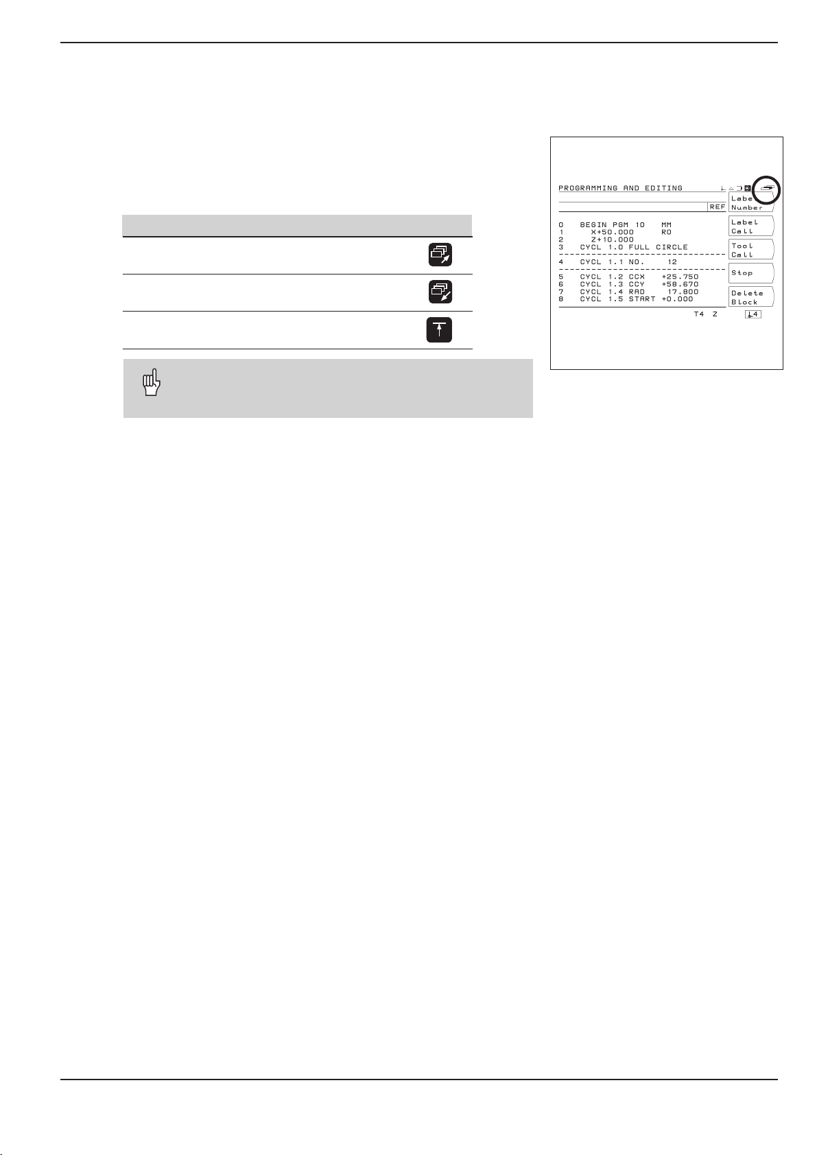
Editing programs
Operating mode: PROGRAMMING AND EDITING
Use the paging keys to display the programmable functions in the
different soft key rows. The screens shown at the right already
contain some program blocks. Turn to the next page of this manual
to learn how program blocks are entered.
Edit the last program selected
with Program Number,
such as program number 10.
The first soft key row provides
/
/
/
functions for entering and changing
coordinates.
The second soft key row provides
the following functions:
Enter labels for subprograms
and program section repeats
Call tool data
Interrupt program
Delete program blocks
The third soft key row provides
functions for entering bolt hole
circles, linear hole patterns or
rectangular pockets.
POSITIP 855 Operating Instructions 47
Page 50

I - 4 Programming POSITIP
Entering program blocks
Current block
The current block is shown between the two dashed lines. New
blocks are inserted behind the current block. When the END PGM
block is between the dashed lines, no new blocks can be inserted.
Function Soft Key/Key
Go up one block
Go down one block
Clear numerical entry
Delete current block
Going directly to a program block
Scrolling to the desired block with the arrow keys can be timeconsuming with long programs. A quicker way is to use the GOTO
function. This enables you to move directly to the block you wish
to change or add new blocks behind.
Operating mode: PROGRAMMING AND EDITING
GOTO
Block number ?
CE
Select Edit.
Press the GOTO key.
5 8
ENT
Enter a block number, such as 58.
Confirm your entry.
Block number 58 is now the currently selected block.
48 Operating Instructions POSITIP 855
Page 51

I - 4 Programming POSITIP
Entering program blocks
Example: Milling a shoulder
The coordinates are programmed in absolute dimensions.
The datum is the workpiece zero.
Corner X = 0 mm Y = 20 mm
Corner X = 30 mm Y = 20 mm
Corner X = 30 mm Y = 50 mm
Corner X = 60 mm Y = 50 mm
1
2
3
4
Summary of all programming steps
ä
In the main menu PROGRAMMING AND EDITING use the
Program Number soft key to access the program directory.
ä
Key in the number of the program you want to work on, and
press ENT.
äÿSelect Edit In the main menu PROGRAMMING AND
EDITING.
ä
Enter the nominal positions.
Running a finished program
When a program is finished it can be run in the EXECUTE PROGRAM mode (see chapter I - 5).
Y
50
20
0
1 2
0
3 4
30
X
60
Example of entry: Entering a nominal position into a program
(block 6 in this example)
Select the coordinate axis (X axis).
Nominal position value ?
3
0
ENT
Program blocks
0 BEGIN PGM 10 MM Start of program, program number and unit of measurement
1 Z+20.000 Clearance height
2X–20.000 R0 Pre-position the tool on the X axis
3Y–20.000 R0 Pre-position the tool on the Y axis
4Z–10.000 Move tool to milling depth
5 Y+20.000 R+ Y coordinate, corner ➀
6 X+30.000 R– X coordinate, corner ➁
7 Y+50.000 R+ Y coordinate, corner ➂
8 X+60.000 R+ X coordinate, corner ➃
9 Z+20.000 Clearance height
10 END PGM 10 MM End of program, program number and unit of measurement
Enter the nominal position value, for example 30 mm
and
select tool radius compensation R .
Confirm the entry. The nominal position is now the current block
(between the dashed lines).
POSITIP 855 Operating Instructions 49
Page 52

I - 4 Programming POSITIP
Calling the tool data in a program
Chapter I - 2 explained how to enter the length and diameter of
your tools in the tool table.
The tool data stored in the table can also be called from a program.
Then if you change the tool during program run you don't need to
select the new tool data from the tool table every time.
The TOOL CALL command automatically pulls the tool length and
diameter from the tool table.
You define the tool axis for program run in the program.
If you enter a different tool axis in the program than is
stored in the table, POSITIP stores the new tool axis in
the table.
Operating mode: PROGRAMMING AND EDITING
Fig. 27: The tool table on the POSITIP screen
Tool number ?
ENT
4
Tool axis ?
Calling datum points
The POSITIP can store up to 99 datum points in a datum table.
You can call a datum point from the datum table during program
run by simply pressing the soft key Datum Call and entering
the block DATUM XX. This automatically calls the datum point entered for XX during program run.
Operating mode: PROGRAMMING AND EDITING
Call tool data from the tool table.
Enter the tool number (such as 4) under which the tool data are stored in the
tool table. Confirm entry.
Enter the tool axis (such as Z).
The program contains the tool call block TOOL CALL 4 Z.
Choose No Entry for the Tool axis if the program already contains a
TOOL CALL block with tool data.
/
Go to the third soft-key row.
Call a datum point from the table.
D a t u m n u m b e r ?
5
50 Operating Instructions POSITIP 855
ENT
Enter the datum number (such as 5).
Confirm entry. Input range: 1 to 99.
Page 53

I - 4 Programming POSITIP
Transferring positions: Teach-in mode
Teach-in programming offers the following three options:
Enter nominal position, transfer nominal position to program,
move to positions by traversing to display value zero:
TEACH-IN / DISTANCE TO GO
Move to a position and transfer the actual value to a program:
TEACH-IN / ACTUAL POSITION
Probe workpiece edges and transfer probed positions:
TEACH-IN / EDGE FINDER
You can change transferred position values with TEACH-IN /
PROGRAM.
Preparation
ä
With Program number select the program you want to transfer positions into.
ä
Select the tool data from the tool table.
or
äÿ
Enter the length and diameter of the edge finder stylus.
Overview of functions
Function Soft Key/Key
Abort and return to the
Teach-In main menu
Go to the previous program block
Go to the next program block
Delete the current block
POSITIP 855 Operating Instructions 51
Page 54

I - 4 Programming POSITIP
Transferring positions: Teach-In mode
Programming example for TEACH-IN / DISTANCE TO GO :
Generate a program while machining a pocket
With Teach-in you first machine a workpiece according to the
workpiece drawing dimensions. POSITIP then transfers the coordinates directly into the program. Pre-positioning and retraction
movements can be selected as desired and entered like drawing
dimensions.
Corner point X = 15 mm Y = 12 mm
Corner point X = 15 mm Y = 47 mm
Corner point X = 53 mm Y = 47 mm
Corner point X = 53 mm Y = 12 mm
1
2
3
4
Pocket depth Z = 10 mm (for example)
Operating mode: PROGRAMMING AND EDITING
Select Teach-In.
The functions for TEACH-IN / DISTANCE TO GO
are available immediately in the first soft key row.
Example: Transfer the Y coordinate of corner point into
a program
Y
53
3
4
X
47
12
0
3
2
1
0
15
Select coordinate axis (Y axis).
Nominal position value ?
4 7
ENT
Enter the nominal position value (such as 47 mm)
and
select tool radius compensation R .
Confirm entry: Y + 47.000 R –
POSITIP displays the positioning aid for traversing to zero.
Traverse the entered axis until the display value is zero.
Then enter and transfer any other coordinates.
52 Operating Instructions POSITIP 855
Page 55

I - 4 Programming POSITIP
Y
X
Z
Transferring positions: Teach-In mode
Programming example for TEACH-IN / ACTUAL POSITION
Touch island with tool and transfer positions to program
With TEACH-IN / ACTUAL POSITION you can generate a
program containing the actual positions of the tool.
When you then run the program:
➤ Use a tool which has the same diameter as the tool you used
during the Teach-In process.
➤ If you use a different tool, you must enter all program blocks
with radius compensation. Then enter the difference between
the radii of the two tools as the tool radius for machining:
Radius of the tool for machining
Radius of the tool for Teach-In
= Tool radius to be entered for machining
Operating mode: PROGRAMMING AND EDITING
Select Teach-In.
/
Example: Transfer Z coordinate (workpiece surface) to a program
Go to TEACH-IN / ACTUAL POSITION.
Move the tool until it touches the workpiece surface.
Select the tool axis (Z).
Transfer actual value Z ?
ENT
Transfer the actual value for the Z axis into the program.
POSITIP 855 Operating Instructions 53
Page 56

I - 4 Programming POSITIP
Transferring positions: Teach-In mode
Programming example for TEACH-IN / EDGE FINDER :
Probe island and transfer positions to a program
Probe the positions on a workpiece with a HEIDENHAIN KT Edge
Finder. The function TEACH-IN / EDGE FINDER transfers the
probed positions into a program.
The Edge Finder transfers the actual workpiece
positions into the program.
Operating mode: PROGRAMMING AND EDITING
Select Teach-In.
/
Example: Probe and transfer position on the X axis
Go to TEACH-IN / EDGE FINDER.
Z
Y
X
Pre-position the Edge Finder near position you wish to probe.
Select the coordinate axis for which the value is to be transferred: X.
Select radius compensation for later machining.
Probe in X axis
Move the Edge Finder against the workpiece edge until the LEDs
light up.
The coordinate of the probed position is now stored in the program.
Retract the Edge Finder. Probe and transfer any further positions
in the same manner.
54 Operating Instructions POSITIP 855
Page 57

I - 4 Programming POSITIP
Transferring positions: Teach-In mode
Changing nominal positions after they have been transferred
Positions which you have transferred into a program with Teach-In
can be changed. It is not necessary to leave the Teach-in mode to
do so.
Enter the new value in the input line.
Example: Change a block transferred with Teach-in
Operating mode: PROGRAMMING AND EDITING, Teach-In
/
/
Go to TEACH-IN / PROGRAM.
With the arrow keys (or GOTO), move to the block you wish to change.
Select the block.
Nominal position value ?
3 0
ENT
Functions for changing a Teach-In program
Function Soft Key
Abort and return to main menu
PROGRAMMING AND EDITING
Enter a new nominal position value (such as 30 mm)
and
change the tool radius compensation.
Confirm your changes.
Delete current block
POSITIP 855 Operating Instructions 55
Page 58

I - 4 Programming POSITIP
Hole patterns in programs
The information for hole patterns can also be written to a program.
Each piece of information is then stored in a separate program
block. These blocks are identified by CYCL after the block
number, followed by a number.
The cycles contain all information required by POSITIP for machining a hole pattern.
There are three cycles for hole patterns:
• CYCL 1.0 FULL CIRCLE
• CYCL 2.0 CIRCLE SEGMENT
• CYCL 4.0 LINEAR HOLE PATTN
Do not delete any blocks from the cycle because this will result in
the error message CYCLE INCOMPLETE when the program is
executed.
Hole pattern graphics
The hole patterns in a program can be displayed graphically.
Programming example: Bolt hole circle (full circle)
Number of holes 8
Coordinates of center X = 50 mm
Y = 50 mm
Bolt circle radius 20 mm
Starting angle between
X axis and first hole 30°
Hole depth Z = 5 mm
Example: Entering bolt circle data into a program
Operating mode: PROGRAMMING AND EDITING
Select Edit.
/
Go to the third soft key row.
50
Y
30°
R20
0
0
50
X
Select Circle Pattern.
The soft key row changes.
Type of bolt circle ?
Select Full Circle. POSITIP calculates the hole positions on a full circle.
56 Operating Instructions POSITIP 855
Page 59

I - 4 Programming POSITIP
Hole patterns in programs
Number of holes ?
ENT
8
Center point X ?
5 0
ENT
Center point Y ?
5 0
ENT
Radius ?
2 0
ENT
Enter the number of holes (NO. = 8).
Confirm your entry.
Enter the X coordinate of the bolt circle center (CCX = 50 mm).
Confirm your entry.
Enter the Y coordinate of the bolt circle center (CCY = 50 mm).
Confirm your entry.
Enter the radius of the bolt circle (RAD = 20 mm).
Confirm your entry.
Starting angle ?
3 0
ENT
Enter the starting angle from the X axis to the first hole (START = 30°).
Confirm your entry.
Hole depth ?
ENT
5
Program blocks
0 BEGIN PGM 20 MM Start of program, program number, unit of measurement
1 Z+20.000 Clearance height
2 CYCL 1.0 FULL CIRCLE Cycle data for a full circle follow
3 CYCL 1.1 NO. 8 Number of holes
4 CYCL 1.2 CCX +50.000 X coordinate of the center of the bolt circle
5 CYCL 1.3 CCY +50.000 Y-coordinate of the center of the bolt circle
6 CYCL 1.4 RAD 20.000 Radius
7 CYCL 1.5 START +30.000 Starting angle of first hole
8 CYCL 1.6 DEPTH –5.000 Hole depth
9 Z+20.000 Clearance height
10 END PGM 20 MM End of program, program number, unit of measurement
Enter the hole depth (DEPTH = –5 mm).
Confirm your entry.
Choose No entry for the hole depth if (for example) the holes
will be drilled to different depths.
For a circle segment (CYCL 2.0 CIRCLE SEGMENT),
you also enter the angle step (STEP) between the holes
(after the starting angle).
The bolt hole circle is then executed in the EXECUTE PROGRAM
operating mode.
POSITIP 855 Operating Instructions 57
Page 60

I - 4 Programming POSITIP
Hole patterns in programs
Programming example: Linear hole pattern (row of holes)
X coordinate of the first hole X = 20 mm
Y coordinate of the first hole Y = 15 mm
Number of holes per row 4
Hole spacing 10 mm
Angle between hole row and X axis 18°
Hole depth Z = 5 mm
Number of rows 3
Row spacing 12 mm
Example: Enter data for linear hole pattern into a program
Operating mode: PROGRAMMING AND EDITING
Select Edit.
15
0
Y
10
1
12
18°
X
0
20
/
Go to the third soft key row.
Select Linear Pattern.
1st hole X ?
2
ENT
0
Enter the X coordinate of hole (POSX = 20 mm).
Confirm your entry.
1st hole Y ?
1 5
ENT
Enter the Y coordinate of hole (POSY = 15 mm).
Confirm your entry.
Holes per row ?
ENT
4
Enter the number of holes per row (NO.HL = 4).
Confirm your entry.
1
1
58 Operating Instructions POSITIP 855
Page 61

I - 4 Programming POSITIP
Hole patterns in programs
Hole spacing ?
1
ENT
0
Angle ?
1 8
ENT
Hole depth ?
ENT
5
Number of rows ?
ENT
3
Enter the hole spacing (HLSPC = 10 mm).
Confirm your entry.
Enter the angle between the X axis and the rows of holes (ANGLE = 18°).
Confirm your entry.
Enter the hole depth (DEPTH = –5 mm).
Confirm your entry.
Select No Entry for Hole depth if, for example, holes
are to be drilled to different depths.
Enter the number of rows (NO.RW = 3).
Confirm your entry.
Row spacing ?
1 2
Program blocks
0 BEGIN PGM 80 MM Start of program, program number, unit of measurement
1 Z+20.000 Clearance height
2 CYCL 4.0 LINEAR HOLE PATTN Cycle data for linear hole pattern follow
3 CYCL 4.1 POSX +20.000 X coordinate of first hole
4 CYCL 4.2 POSY +15.000 Y coordinate of first hole
5 CYCL 4.3 NO.HL 4 Number of holes per row
6 CYCL 4.4 HLSPC +10.000 Distance between holes on the row
7 CYCL 4.5 ANGLE +18.000 Angle between the rows and the X axis
8 CYCL 4.6 DEPTH –5.000 Hole depth
9 CYCL 4.7 NO.RW 3 Number of rows
10 CYCL 4.8 RWSPC +12.000 Spacing between rows
11 Z+20.000 Clearance height
12 END PGM 80 MM End of program, program number, unit of measurement
The hole pattern is then executed in the EXECUTE PROGRAM operating mode.
ENT
Enter the row spacing (RWSPC = 12 mm).
Confirm your entry.
POSITIP 855 Operating Instructions 59
Page 62

I - 4 Programming POSITIP
Rectangular pocket milling in programs
The POSITIP makes the roughing out of rectangular pockets simple: You just enter the dimensions for the pocket, and POSITIP
calculates the rough-out paths.
Execution of cycle
The execution of the cycle is represented in Figs 7.6, 7.7 and 7.8.
I:
The POSITIP gives the distances-to-go for positioning the tool at
the starting position
machining plane to the center of the pocket.
A
: first in the tool axis, and then in the
II:
Roughing out the pocket in accordance with the path indicated in
the diagram (Fig. 7.8 shows climb milling). In the working plane
the stepover distance is equal to the tool radius
depth in the tool axis is random.
III:
This procedure repeats itself until the entered depth B is reached.
Input into cycle 5.0 RECTANGULAR POCKET
Starting position - STARTPOS.
(enter absolute value, referenced to datum)
Milling depth - DEPTH
B
(enter absolute value, referenced to datum)
Pocket center in X - POSX
Center of the pocket in the main axis of the working plane.
Pocket center in Y - POSY
Center of the pocket in the secondary axis of the working
plane.
Side length in X - LENGTH X
Length of the pocket in the direction of the main axis.
Side length in Y - LENGTH Y
Length of the pocket in the direction of the secondary axis.
Direction DIR.
Input value 0: Climb milling (Fig. 7.8: anticlockwise)
Input value 1: Up-cut milling (clockwise)
Finishing allowance - FIN.AL
Finishing allowance in the working plane.
A
MX
MY
X
Y
R
. The pecking
I
Z
Fig. 7.6: Step I in cycle
5.0 RECTANGULAR POCKET
II
Z
Fig. 7.7: Step II in cycle
5.0 RECTANGULAR POCKET
III
MX
Y
A
X
B
X
X
Y
MY
R
X
Fig. 7.8: Step III in cycle
5.0 RECTANGULAR POCKET
60 Operating Instructions POSITIP 855
Page 63

I - 4 Programming POSITIP
Rectangular pocket milling in programs
Programming example: Mill rectangular pocket
Starting position: 2 mm
Milling depth: 20 mm
Pocket center in X: 50 mm
Pocket center in Y: 40 mm
Side length in X: 80 mm
Side length in Y: 60 mm
Direction: 0: CLIMB
Finishing allowance: 0.5 mm
Example: Entering rectangular pocket data into a program
Operating mode: PROGRAMMING AND EDITING
Select EDIT.
–20
–30
80
70
40
10
Z
0
X
Y
R10
0
0
10
50
90
X
100
/
Go to the third soft-key row.
Select cycle 5.0 POCKET MILLING.
S t a r t i n g p o s i t i o n ?
ENT
2
Enter the starting position (2 mm ).
Confirm your entry.
M i l l i n g d e p t h ?
2
ENT
0
Enter the milling depth ( - 20 mm ).
Confirm your entry.
POSITIP 855 Operating Instructions 61
Page 64

I - 4 Programming POSITIP
Rectangular pocket milling in programs
Program blocks
0 BEGIN PGM 55MM Start of program, program number, unit of measurement
1 CYCL 5.0 RECT. POCKET Cycle data for cycle 5.0 RECTANGULAR POCKET
2 CYCL 5.1 START 2 Starting position above the workpiece surface
3 CYCL 5.2 DEPTH – 20 Milling depth
4 CYCL 5.3 POSX + 50 Pocket center in X
5 CYCL 5.4 POSY + 40 Pocket center in Y
6 CYCL 5.5 LGTHX 80 Side length in X
7 CYCL 5.6 LGTHY 60 Side length in Y
8 CYCL 5.7 DIR. 0 :CLIMB Climb milling
9 CYCL 5.8 FIN.AL 0.5 Finishing allowance
10 END PGM 55 MM End of program, program number, unit of measurement
Cycle 5.0 RECTANGULAR POCKET is then run in the EXECUTE PRO-
GRAM operating mode (see Chapter I-5).
62 Operating Instructions POSITIP 855
Page 65

I - 4 Programming POSITIP
Entering program interruptions
You can divide a program into sections with stop marks. POSITIP
then only executes the next block when you press the soft key
Next Block.
Operating mode: PROGRAMMING AND EDITING
Choose Edit.
/
Go to the second soft key row.
Press Stop to insert a program interruption.
POSITIP 855 Operating Instructions 63
Page 66

I - 4 Programming POSITIP
Subprograms and program section repeats
Subprograms and program section repeats only need to be entered
once in the program. You can then run them up to 999 times.
Subprograms can be run at any point in the program, while program section repeats are run several times in succession.
Inserting program marks (labels)
You identify subprograms and program section repeats with labels
(abbreviated in the program to LBL).
Labels 1 to 99
Labels 1 to 99 identify the beginning of a subprogram or a program
section which is to be repeated.
Label 0
Label 0 is used only to identify the end of a subprogram.
Label call
In the program, subprograms and program sections are called with
the command CALL LBL.
The command CALL LBL 0 is not allowed.
Subprograms:
After a CALL LBL block in the program, POSITIP executes the
called subprogram.
Program section repeats:
POSITIP repeats the program section located before the CALL
LBL block. You enter the number of repeats with the CALL LBL
command.
Nesting program sections
Subprograms and program section repeats can also be "nested."
For example, a subprogram can in turn call another subprogram.
Maximum nesting depth: 8 levels.
Fig. 28: On-screen operating instructions for
subprograms (page 5 shown)
Fig. 29: On-screen operating instructions for
program section repeats (page 3
shown)
64 Operating Instructions POSITIP 855
Page 67

I - 4 Programming POSITIP
Subprograms and program section repeats
Subprogram
Programming example: Subprogram for slots
Slot length: 20 mm + tool diameter
Slot depth: 10 mm
Slot diameter: 8 mm (= tool diameter)
Coordinates of the recess point
1
Slot X = 20 mm Y = 10 mm
2
Slot X = 40 mm Y = 50 mm
3
Slot X = 60 mm Y = 40 mm
A center-cut end mill
(DIN 844) is required for carrying out this example!
Example: Insert label for subprogram
Operating mode: PROGRAMMING AND EDITING
Select Edit.
/
Go to the second soft key row.
50
40
10
Y
8
20
2
3
20
1
X
40
60
0
0
Insert a label (LBL) for a subprogram.
POSITIP offers the lowest available label number.
Label number ?
ENT
ENT
1
The beginning of a subprogram (or a program section repeat) is
now marked with the label. Enter the program blocks for the
subprogram after the LBL block.
Label 0 (LBL 0) is used only to identify the end of a subprogram.
Accept the default label number.
Enter a label number (here, 1). Confirm your entry.
The current block now contains the label LBL 1.
POSITIP 855 Operating Instructions 65
Page 68

I - 4 Programming POSITIP
Subprograms and program section repeats
Example: Enter a subprogram call: CALL LBL
/
Go to the second soft key row.
Call the label.
POSITIP offers the label number which was last set.
Label number ?
ENT
ENT
1
After the CALL LBL block in the EXECUTE PROGRAM operating
mode, POSITIP executes those blocks in the subprogram that are
located between the LBL block with the called number and the
next block containing LBL 0.
Note that the subprogram will be executed at least once even without a CALL LBL block.
Accept the default label number.
Enter a label number (here, 1). Confirm your entry.
The current block now contains the called label: CALL LBL 1.
For subprograms you can ignore the question "Repeat REP ?".
Press the soft key to confirm that a subprogram is being called.
Program blocks
0 BEGIN PGM 30 MM Start of program, program number, unit of measurement
1 Z+20.000 Clearance height
2 X+20.000 R0 X coordinate of recess point slot ➀
3 Y+10.000 R0 Y coordinate of recess point slot ➀
4 CALL LBL 1 Call subprogram 1: execute blocks 12 to 16
5 X+40.000 R0 X coordinate of recess point slot ➁
6 Y+50.000 R0 Y coordinate of recess point slot ➁
7 CALL LBL 1 Call subprogram 1: execute blocks 12 to 16
8 X+60.000 R0 X coordinate of recess point slot ➂
9 Y+40.000 R0 Y coordinate of recess point slot ➂
10 CALL LBL 1 Call subprogram 1: execute blocks 12 to 16
11 Z+20.000 Clearance height
12 LBL 1 Start of subprogram 1
13 Z–10.000 Recess to slot depth
14 IY+20.000 R0 Mill slot
15 Z+2.000 Retract
16 LBL 0 End of subprogram 1
17 END PGM 30 MM Program end, program number and measuring unit
66 Operating Instructions POSITIP 855
Page 69

I - 4 Programming POSITIP
Subprograms and program section repeats
Program section repeats
A program section repeat is entered like a subprogram. The end of
the program section is identified simply by the command to repeat
the section.
Label 0 is therefore not set.
Display of the CALL LBL block with a program section repeat
The screen displays (for example): CALL LBL 1 REP 10 / 10 .
The two numbers with the slash between them indicate that this is
a program section repeat. The number in front of the slash is the
number of repeats you entered. The number behind the slash is
the number of repeats remaining to be performed.
Programming example: Program section repeat for slots
Slot length: 16 mm +tool diameter
Slot depth: 12 mm
Incremental offset of the
recess point: 15 mm
Slot diameter: 6 mm (= tool diameter)
Coordinates of the recess point
1
Slot
: X = 30 mm Y = 10 mm
A center-cut end mill (DIN 844)
is required for carrying out this example!
Example: Insert a label for a program section repeat
Operating mode: PROGRAMMING AND EDITING
Select Edit.
/
Go to the second soft key row.
70
55
40
25
10
Y
6
16
1
0
0
30
X
Set a program mark (LBL) for a program section repeat.
POSITIP offers the lowest available label number as a default.
Label number ?
ENT
ENT
1
Enter the blocks for the program section repeat after the LBL block.
POSITIP 855 Operating Instructions 67
Accept the default label number.
Enter a label number (here, 1). Confirm your entry.
The current block now contains the set label: LBL 1.
Page 70

I - 4 Programming POSITIP
Subprograms and program section repeats
Example: Entering a program section repeat: CALL LBL
/
Go to the second soft key row.
Call label.
POSITIP offers the label number that was last set.
Label number ?
ENT
ENT
1
Accept the default label number.
Enter a label number (here, 1) and confirm your entry.
The called label is now in the current block: CALL LBL 1.
Repeat REP ?
ENT
4
After a CALL LBL block in the PROGRAMMING AND EDITING
operating mode, POSITIP repeats those program blocks that are
located behind the LBL block with the called number and before
the CALL LBL block.
Note that the program section will always be executed one more
time than the programmed number of repeats.
Enter the number of repeats (here, 4) and confirm your entry.
Program blocks
0 BEGIN PGM 70 MM Start of program, program number, unit of measurement
1 Z+20.000 Clearance height
2 X+30.000 R0 X coordinate recess point slot
3 Y+10.000 R0 Y coordinate recess point slot
1
1
4 LBL 1 Start of program section 1
5 Z-12.000 Recess
6 IX+16.000 R0 Mill slot
7 Z+2.000 Retract
8 IX-16.000 R0 Position in X
9 IY+15.000 R0 Position in Y
10 CALL LBL 1 REP 4 / 4 Repeat program section 1 four times
11 Z+20.000 Clearance height
12 END PGM 70 MM End program, program number, unit of measurement
68 Operating Instructions POSITIP 855
Page 71

I - 4 Programming POSITIP
Editing existing programs
You can edit existing programs, for example to correct keying
errors. POSITIP supports you with plain language dialogs just as
when you are creating a new program.
Program numbers can be changed by selecting the BEGIN or
END block and entering a new program number.
Confirm your changes
You must confirm each change with the ENT key for it to become
effective.
Example: Editing a program block
/
Move to the block you wish to edit.
Select the block.
2 0
ENT
Edit the block, for example enter a new nominal position value (here, 20).
Confirm the change.
Function Key
Select the next-lowest program block
Select the next-highest program block
Go directly to program block number
Select program block to edit
GOTO
Confirm change
ENT
POSITIP 855 Operating Instructions 69
Page 72

I - 4 Programming POSITIP
Deleting program blocks
You can delete any blocks in existing programs except the BEGIN
and END blocks.
When a block is deleted, POSITIP automatically renumbers the
remaining blocks. The block before the deleted block then becomes
the current block.
Example: Deleting a program block
Operating mode: PROGRAMMING AND EDITING
Select Edit.
/
/
It is also possible to delete an entire program section:
➤ Select the last block of the program section.
➤ Press the soft key Delete Block repeatedly until all
blocks in the program section have been deleted.
Move to the block you wish to delete
(or use the GOTO key).
Go to the second soft key row.
Press Delete Block.
70 Operating Instructions POSITIP 855
Page 73

I - 4 Programming POSITIP
Transferring programs over the data interface
The RS-232-C interface on the rear panel allows you to utilize a
device such as the HEIDENHAIN FE 401 floppy disk unit or a PC
for external data storage.
Programs can also be archived on diskette and loaded back into
POSITIP again as required.
Pin layout, wiring and connections for the data interface
are described in chapter II - 4.
Function Soft Key/Key
Directory of programs
stored in POSITIP
Directory of programs
stored on the FE
Abort data transfer
Switch FE EXT
Show further programs
Example: Transferring a program into POSITIP
Operating mode: PROGRAMMING AND EDITING
Select External.
Program number ?
5
/
Enter the program number (here, 5).
Select external device (for diskette unit or PC with HEIDENHAIN data transfer
software TNC.EXE, use FE setting; for PC without TNC.EXE, use EXT setting).
Press Start Input to transfer the program to POSITIP.
The message Loading program: appears on the POSITIP screen
If you are transferring programs into POSITIP from a PC (EXT
setting), the PC must send the programs.
If POSITIP's memory already contains a program with the same
number as that being transferred, the error message
PROGRAM ALREADY EXISTS will appear on the screen.
In this case, before you can transfer the program you must either
rename or delete the program in POSITIP.
POSITIP 855 Operating Instructions 71
Page 74

I - 4 Programming POSITIP
Transferring programs over the data interface
For program output, POSITIP automatically displays all programs in
its memory.
Example: Reading a program out of POSITIP
Operating mode: PROGRAMMING AND EDITING
Select External.
/
Go to EXTERNAL OUTPUT.
Program number ?
1
0
C A U T I O N
A program on the external device with the same number
as that being read out will be overwritten. No
confirmation to overwrite will be requested.
To read all programs out of POSITIP:
Enter the program number (here, 10).
Select the external device.
For diskette unit or PC with HEIDENHAIN data transfer software TNC.EXE,
use FE setting; for PC without TNC.EXE (or printer), use EXT setting.
Press Start Output to transfer the program to the external device.
The message Reading out program: appears.
ä
Press Output All PGM soft key.
72 Operating Instructions POSITIP 855
Page 75

I - 5 Executing Programs
I-5
Executing Programs
Programs are run in the EXECUTE PROGRAM operating mode. The
current program block is displayed at the top of the screen.
There are two ways to run programs:
Single Block
When you have moved the axis to the displayed position, call the
next block with the Next Block soft key. It is recommended that
you use Single Block when running a program for the first
time.
Automatic
Here the display automatically shows the next program block as
soon as you have moved to the displayed position. Use Auto-
matic when you are sure the program contains no errors and you
want to run it quickly.
Preparation
ä
Mount the workpiece on the machine table.
ä
Set the reference point for the workpiece.
ä
Select the program with Program number in the main menu
EXECUTE PROGRAM.
Single Block
Operating mode: EXECUTE PROGRAM
Select Single Block.
The program block and the graphic positioning cursor appear.
Position by "traversing to zero."
Call next program block.
Continue positioning and calling blocks with Next Block until
machining is complete.
An overview of functions is shown on the next page.
POSITIP 855 Operating Instructions 73
Page 76

I - 5 Executing Programs
Automatic
Operating mode: EXECUTE PROGRAM
The display automatically shows the next program block as soon
as you have moved to the displayed position. The positioning aid
automatically switches to the coordinate axis of the new block.
Function Soft Key/Key
Start with the block before the
current block
Start with the block after the
current block
Select the starting block directly
Select Automatic.
The program block and the graphic positioning cursor appear.
Position by traversing to display value zero.
GOTO
Enter the tool data
With hole patterns:
Display pattern graphically
After starting:
Abort return to menu
74 Operating Instructions POSITIP 855
Page 77

I - 6 INFO: Pocket Calculator, Stopwatch, Cutting Data Calculator
I-6
The INFO Functions: Pocket Calculator, Stopwatch
and Cutting Data Calculator
Press the INFO key to access the following functions:
Cutting data calculator
Calculates the spindle speed from the tool diameter and the
cutting speed;
Calculates the feed rate from the spindle speed, the number of
teeth and the depth of cut per tooth.
Stopwatch
Pocket calculator
Basic arithmetic functions (+ , , ´, ÷ )
Trigonometric functions (sin, cos, tan, arc sin, arc cos, arc tan)
Square roots
2
x
Reciprocals (1/x)
p (3.14159...)
INFO
To access the INFO functions
INFO
Press the INFO key.
Cutting Data for milling
Select Stopwatch.
Select Calculator functions
POSITIP 855 Operating Instructions 75
Page 78

I - 6 INFO: Pocket Calculator, Stopwatch, Cutting Data Calculator
Cutting data: Calculate spindle speed S and feed rate F
POSITIP can calculate the spindle speed S and the feed rate F for
you. As soon as you conclude an entry with ENT, POSITIP
prompts you for the next entry.
Entry values
For the spindle speed S in rpm:
Enter the tool diameter D in mm and the cutting speed V in
m/min.
For the feed rate F in mm/min:
Enter the spindle speed S in rpm,
the number of teeth n of the tool and
the permissible depth of cut per tooth d in mm.
For calculation of the feed rate, POSITIP automatically offers the
spindle speed it just calculated. You can enter a different value,
however.
Function Key
Confirm entry and continue dialog
ENT
INFO
Go to the next-higher input line
Go to the next-lower input line
Example: Entering the tool diameter
You can be in any operating mode. Select Cutting Data.
Tool diameter ?
ENT
8
Enter the tool diameter (8 mm) and transfer it into the box behind the letter D.
76 Operating Instructions POSITIP 855
Page 79

I - 6 INFO: Pocket Calculator, Stopwatch, Cutting Data Calculator
Stopwatch
The stopwatch shows the hours (h), minutes (), seconds () and
hundredths of a second.
The stopwatch continues to run even when you leave the INFO
function. When the power is interrupted (switch-off), POSITIP
resets the stopwatch to zero.
Function Soft Key
Reset the stopwatch to zero and start
Stop timing
Pocket calculator
INFO
The pocket calculator functions are spread over three soft key
rows:
Basic arithmetic (first soft key row)
Trigonometry (second row)
Square root, x
2
, 1/x, p (third row)
Use the paging keys to go from one soft key row to the next.
POSITIP always shows an example entry you don't have to
press the HELP key.
Transferring the calculated value
The calculated value remains in the input line even after you leave
the pocket calculator function.
This allows you to transfer the calculated value directly into a program as a nominal position without having to reenter it.
Entry logic
For calculations with two operands (addition, subtraction, etc.):
ä
Key in the first value.
ä
Confirm the value by pressing ENT.
ä
Key in the second value.
ä
Press the soft key for the desired operation.
POSITIP displays the result of the operation in the input line.
For calculations with one operand (sine, reciprocal, etc.):
ä
Key in the value.
ä
Press the soft key for the desired operation.
POSITIP displays the result of the operation in the input line.
Example: See the next page.
POSITIP 855 Operating Instructions 77
Page 80

I - 6 INFO: Pocket Calculator, Stopwatch, Cutting Data Calculator
Pocket calculator functions
Example: (3 ´ 4 + 14) ÷ (2 ´ 6 + 1) = 2
INFO
ENT
3
4
1
4
ENT
2
6
Key in the first value in the first parenthesis: 3; confirm entry.
The display shows +3.000.
Key in the second value in the first parenthesis: 4
and
combine the second value with the first value: ´.
The display now shows +12.000.
Key in the third value in the first parenthesis: 14
and
combine the third value with the displayed value 12.000: +.
The display now shows +26.000.
Key in the first value in the second parenthesis: 2; confirm entry.
This automatically closes the first parenthesis.
The display shows +2.000.
Key in the second value in the second parenthesis: 6
and
combine the second value with the first value: ´.
The display now shows +12.000.
1
Key in the third value in the second parenthesis: 1
and
combine the third value with the displayed value 12.000: +.
The display now shows +13.000.
Close the second parenthesis and simultaneously
combine with the first parenthetical expression: ÷.
The display now shows the result: +2.000.
78 Operating Instructions POSITIP 855
Page 81

I - 7 User Parameters: The MOD Function
I-7
User Parameters: The MOD Function
User parameters are operating parameters which you can change
without having to enter a code number.
The machine builder determines which operating parameters are
available to you as user parameters as well as how the user parameters are arranged in the soft keys.
The functions of user parameters are described in chapter II - 2.
To access the user parameter menu
ä
Press MOD.
The user parameters appear on the screen.
ä
Go to the soft key row with the desired user parameter.
ä
Press the soft key for the desired user parameter.
MOD
To leave the user parameter menu
ä
Press MOD.
Scaling factors
The user parameter Scaling Factor enables you to increase
or decrease the size of workpieces. POSITIP divides the displayed
value by the scaling factor you entered.
Scaling factors change the workpiece size symmetrically about the
workpiece datum. The workpiece datum should therefore be located at an edge when you are working with scaling factors.
Input range: 0.1 to 9.999 999
To activate scaling factors
ä
Switch the user parameter Scaling Factor OFF / ON
to ON.
To deactivate scaling factors
ä
Switch the user parameter Scaling Factor OFF / ON
to OFF.
Please see next page for instructions on entering scaling factors.
Fig. 30: The user parameters on the POSITIP
screen
Y
∗ 3.0
1
0
2
∗ 3.5
X
0
Fig. 31: Original workpiece
1
2
After enlargement with scaling
factor
POSITIP 855 Operating Instructions 79
Page 82

I - 7 User Parameters: The MOD Function
Entering user parameters
Choosing settings
Some user parameter settings are chosen directly with the soft
keys. You simply switch from one setting to the other.
Example: Angle format
ä
Press MOD.
The MOD main menu now contains either the soft key
Deg. decimal or Deg/Min/Sec
ä
Press the displayed soft key.
The soft key changes to the other setting, for example from
Deg. decimal to Deg/Min/Sec
ä
Press MOD again.
This ends the MOD function.
The new setting for the angle format is now in effect.
Entering values
Some user parameters require that you enter a value or select a setting from a number of possible settings. When you press the soft
key, a menu for the parameter is displayed.
MOD
Example: Scaling factor for the Z axis
ä
Press MOD.
ä
Press the Scaling Z soft key.
POSITIP now displays an input screen for the scaling factor.
ä
Key in the desired scaling factor.
ä
Press ENT.
If you want this scaling factor to apply to all coordinate axes,
press the Set All soft key.
The MOD main menu is then displayed.
ä
Press MOD again.
This ends the MOD function.
The new setting for the scaling factor is now in effect.
When you are working with scaling factors, the soft key
Scaling OFF/ON must be set to ON.
80 Operating Instructions POSITIP 855
Page 83

Part II: Technical Information
II - 1 Installation and Electrical Connection......................................83
Items supplied .................................................................................................. 83
Installation ........................................................................................................ 83
Connecting the encoders .................................................................................. 84
Connecting an edge finder ................................................................................ 85
Initial switch-on ................................................................................................ 85
II - 2 Operating Parameters ...............................................................86
To access the operating parameters ................................................................. 86
Transferring operating parameters over the data interface ................................. 87
User parameters ............................................................................................... 88
List of operating parameters ............................................................................. 89
II - 3 Encoders and Measured Value Display ................................... 92
Adapting the encoders ...................................................................................... 92
Setting the display step with linear encoders .................................................... 94
Setting the display step with angle encoders .................................................... 96
Setting the measured value display .................................................................. 97
Axis error compensation ................................................................................... 98
II
II - 4 Data Interface ...........................................................................100
II - 5 Measured Value Output ..........................................................102
Starting measured value output ...................................................................... 102
Operating parameters for measured value output ........................................... 104
Examples of character output at the data interface ......................................... 105
II - 6 Switching Inputs and Outputs ...............................................107
II - 7 Specifications ...........................................................................110
II - 8 Dimensions ..............................................................................111
Front view ....................................................................................................... 111
Top view ......................................................................................................... 111
Rear view ....................................................................................................... 112
Tilting base ..................................................................................................... 112
Subject Index ................................................113
Technical Information
Page 84

Page 85

II - 1 Installation and Electrical Connection
II - 1
Installation and Electrical Connection
Items supplied
POSITIP 855 Display Unit
Power connector
User's Manual
Installation
M4 screws are required for securing POSITIP from below
or on a tilting base from HEIDENHAIN (Id. Nr. 281 619-01).
See chapter II - 8 for the bore hole dimensions.
Electrical connection
WARNING - Electric Shock Danger
Unplug the power cord before opening the housing.
Connect a protective ground.
This connection must never be interrupted.
Danger to internal components!
Do not engage or disengage any connections while
the unit is under power.
Use only original replacement fuses.
Power connection
POSITIP requires AC voltage between 100 V and 240 V
(48 Hz to 62 Hz). No voltage adjustment is required.
Wiring the power connector
See fig. 32
Hot leads: and
Ground:
Minimum diameter of power connection cable: 0.75 mm
L
N
2
Fig. 32: Wiring the power connector
POSITIP 855 Technical Information 83
Page 86

II - 1 Installation and Electrical Connection
X4
2
3
45
7
1
9
6
8
X3 X2 X1X4
Grounding
Noise immunity can be increased by connecting the
ground screw on the rear panel to the star point of
machine ground. Minimum cross section of the
connecting wire: 6 mm
2
.
Connecting the encoders
POSITIP can be used with HEIDENHAIN linear and angle encoders
that provide sinusoidal output signals. The encoder inputs on the
rear panel are designated X1, X2, X3 and X4. The connecting
cable may not exceed 30 m (100 ft) in length.
Danger to internal components!
Do not engage or disengage any connections while
the unit is under power.
Pin layout for encoder inputs
Pin Assignment
1 0°+
2 0°
3 +5 V (UP)
4 0 V (UN)
5 90°+
6 90°
7 Reference mark signal RI+
8 Reference mark signal RI
9 Internal shield
Housing External shield
Fig. 33: The ground screw on the rear panel
Fig. 34: Flange socket on POSITIP for encoder
signal input
The encoder inputs are permanently assigned to 4 axes.
Operating parameter P49.* determines the designation of the
axes, e.g. axis 1 = X axis, axis 2 = Y axis.
Axis Encoder input
1X1
2X2
3X3
4X4
Interfaces X1, X2, X3 and X4 comply with the recommen-
84 Technical Information POSITIP 855
dations in EN 50 178 for separation from line power.
Fig. 35: Encoder inputs on rear panel
Page 87

II - 1 Installation and Electrical Connection
X3 X2 X1
X10X31(V.24 RS-232-C)T)
Connecting an edge finder
Connect the HEIDENHAIN KT Edge Finder to the D-sub input
X10 on the rear panel.
Adapt POSITIP for use with the edge finder through the
following operating parameters:
P25 (stylus length)
P26 (stylus diameter)
P96 (measured-value output during probing)
The operating parameters are described in chapter II - 2.
Pin layout for edge finder input
Pin Assignment Type
1 Internal shield
2 Stand-by KT 130
6 UP +5 V KT 130
8 UP 0 V KT 130
13 Switch signal KT 130
14 Contact +2.5 V KT 120
15 Contact 0 V KT 120
Housing External shield
All other pins: do not assign
Interface X10 complies with the recommendations in
EN 50 178 for separation from line power.
Initial switch-on
When you switch on your POSITIP for the first time, the
screen shown in figure 37 appears. You can now select the
type of application (milling or turning).
Fig. 36: Input X10 for edge finder
For milling:
ä
Press the 0 key
For turning:
äÿPress the 1 key
POSITIP automatically provides the functions appropriate
to the selected application.
You can change the application later with operating
parameter P 99.
Fig. 37: POSITIP screen after initial switch-on
POSITIP 855 Technical Information 85
Page 88

II - 2 Operating Parameters
II - 2
Operating Parameters
Operating parameters adapt the POSITIP to the machine.
They are identified with the letter P, a three-digit number and a
name.
Axis-specific operating parameters
Some parameters must be entered separately for each axis. Such
parameters are identified in the following descriptions with
an asterisk (*).
Example: Operating parameter for the counting direction: P30.*
For this parameter you enter the counting direction separately for
each axis in parameters P30.1, P30.2, P30.3 and P30.4.
Factory settings
The factory settings for the operating parameters in the overview
on the next pages are set in bold italic type.
Numerical input, dialog input
The current setting of an operating parameter is shown in plain
language under the parameter designation in the on-screen
operating parameter list. In addition, each parameter setting has a
number in the input line at the top. These numbers are transferred
when you read out the operating parameters over the data
interface.
Fig. 38: Example of operating parameters
To access the operating parameters
ä
Press MOD.
ä
Go to the soft key row containing Code Number .
(soft key with the key symbol).
ä
Press the soft key Code Number
ä
Enter the code number 95148.
ä
Confirm with ENT.
ä
Display the operating parameters one after the other with the
vertical arrow keys; or
ä
Go directly to an operating parameter:
Press GOTO, enter the parameter number and
confirm with ENT.
To change parameter settings
Operating parameter settings can be changed by selecting the
new setting or entering a numerical value:
ä
Select a new setting: Press the horizontal arrow key.
or
ä
Enter a numerical value directly and confirm your entry with
ENT.
The horizontal arrow key has no function with parameters
which only allow direct numerical entry.
86 Technical Information POSITIP 855
Page 89

II - 2 Operating Parameters
Transferring operating parameters over the data interface
You can archive the operating parameters on the FE 401 B Floppy
Disk Unit or a PC and read them into the POSITIP again whenever
required. For further information on the data interface and data
transfer, see chapter II - 4.
Preparation
ä
Access the operating parameters as described above.
ä
Go to the second soft-key level.
To read out parameters
ä
Enter the program number under which you wish to save the
operating parameters.
ä
Press the Param. Output soft key.
POSITIP reads out all operating parameters.
To download parameters
ä
Enter the program number under which the operating
parameters are stored on the diskette.
ä
Press the Param. Input soft key.
POSITIP replaces all operating parameter settings in its
memory with those on the diskette.
Fig. 39: The POSITIP screen for transfer of
operating parameters
POSITIP 855 Technical Information 87
Page 90

II - 2 Operating Parameters
User parameters
The machine manufacturer has defined certain operating
parameters as user parameters. You can change the settings of
user parameters without having to enter the code number (see
Operating Instructions section, chapter I - 7).
Position of user parameters in the menu
In operating parameters P100 to P122, the machine manufacturer
defines how the user parameters are arranged in the soft keys.
Field 15 is reserved for the Code Number soft key.
If a parameter is assigned field number 0, it will not appear in the
user parameter menu.
11 6 1
12 7 2
13 8 3
Operating User parameter Standard
parameter designation
*)
field
P 100 mm / inch (P 1) 4 ........
P 101.1 Radius / diameter 1 (P 3.1) 0 ........
P 101.2 Radius / diameter 2 (P 3.2) 0 ........
P 101.3 Radius / diameter 3 (P 3.3) 0 ........
P 101.4 Radius / diameter 4 (P 3.4) 0 ........
P 103 Angle format (P 8) 5 ........
P 104 Scaling factor ON/OFF (P 11) 10 ........
P 105.1 Scaling factor 1 (P 12.1) 6 ........
P 105.2 Scaling factor 2 (P 12.2) 7 ........
P 105.3 Scaling factor 3 (P 12.3) 8 ........
P 105.4 Scaling factor 4 (P 12.4) 9 ........
P 109 Edge finder (P 25, P 26) 1 ........
P 112 RS-232-C baud rate (P 50) 11 .......
P 113 RS-232-C line feeds (P 51) 12 .......
P 120 Tool table 2 ........
P 122 Datum table 3 ........
14 9 4
15 10 5
Fig. 40: Fields for user parameters
*)
The corresponding operating parameters are indicated in
parentheses.
88 Technical Information POSITIP 855
Page 91

II - 2 Operating Parameters
List of operating parameters
Parameter Page Function and Numerical
allowed entries entry
*)
P1 mm/inch 97 Dimensions in millimeters: mm 0 P1...............
Dimensions in inches: inch 1
P3.1 Radius/Diameter 1 97 Radius display 0 P3.1 ............
P3.2 Radius/Diameter 2 Diameter display 1 P3.2 ............
P3.3 Radius/Diameter 3 P3.3............
P3.4 Radius/Diameter 4 P3.4............
P6 Axis combination 97 No axis combination: off 0 P6 ...............
1+4 displayed on 1 1 ...................
2+4 displayed on 2 2 ...................
3+4 displayed on 3 3 ...................
14 displayed on 1 4 ...................
24 displayed on 2 5 ...................
34 displayed on 3 6
P8 Angle format 97 Decimal display: Degrees 0 P8 ...............
Degrees/Minutes/Seconds 1
P9.1 Angle counting 1 97 360° 0 P9.1............
P9.2 Angle counting 2 +/ 180° 1 P9.2 ............
P9.3 Angle counting 3 +/ ¥° 2 P9.3 ............
P9.4 Angle counting 4 P9.4............
P11 Scaling factor on 79 Scaling factor inactive: off 0 P11 .............
Scaling factor active: on 1
P12.1 Scaling factor 1 79 Scaling factor P12.1 ..........
P12.2 Scaling factor 2 0.1 bis 9.999 99 1.0 P12.2..........
P12.3 Scaling factor 3 P12.3 ..........
P12.4 Scaling factor 4 P12.4 ..........
P23 Display freeze 104 Ignore signal: off 0 P23 .............
Influence position display by Stop display: concrnt. 1
signal for measured-value output Freeze display: frozen 2
P25 Stylus diameter 0.001 to 999.999 [mm] 6.0 P25 .............
P26 Stylus length 999.999 to 999.999 [mm] 0.0 P26 .............
P30.1 Counting direction 1 93 Positive counting direction 0 P30.1 ..........
P30.2 Counting direction 2 with positive traverse direction P30.2 ..........
P30.3 Counting direction 3 Negative counting direction 1 P30.3 ..........
P30.4 Counting direction 4 with positive traverse direction P30.4 ..........
P31.1 Signal period 1 94 Signal period of linear encoder 20 P31.1 ..........
P31.2 Signal period 2 95 (see Operating Instructions P31.2 ..........
P31.3 Signal period 3 for encoder) P31.3 ..........
P31.4 Signal period 4 P31.4 ..........
P32.1 Linear subdivision 1 94 Linear subdivision of 20 P32.1 ..........
P32.2 Linear subdivision 2 95 encoder signals P32.2 ..........
P32.3 Linear subdivision 3 P32.3 ..........
P32.4 Linear subdivision 4 P32.4 ..........
*)
Standard factory settings are in bold italic type
POSITIP 855 Technical Information 89
Page 92

II - 2 Operating Parameters
List of operating parameters
Parameter Page Function and Numerical
allowed entries entry
1)
P35.1 Line count 1 96 Line count of angle encoder 1 800 P35.1 ..........
P35.2 Line count 2 (see operating instructions P35.2 ..........
P35.3 Line count 3 of encoder) P35.3 ..........
P35.4 Line count 4 P35.4 ..........
P36.1 Angle subdivision 1 96 Angle subdivision of encoder 20 P36.1 ..........
P36.2 Angle subdivision 2 signals P36.2 ..........
P36.3 Angle subdivision 3 P36.3 ..........
P36.4 Angle subdivision 4 P36.4 ..........
P40.1 Error compensation 1 98 No axis error compensation: OFF 0 P40.1 ..........
P40.2 Error compensation 2 99 Linear axis error comp.: Linear 1 P40.2 ..........
P40.3 Error compensation 3 Non-linear axis error P40.3 ..........
P40.4 Error compensation 4 compensation: Non-linear 2 P40.4 ..........
P41.1 Linear compensation 1 98 Amount of linear axis error +0.0 P41.1 ..........
P41.2 Linear compensation 2 compensation P41.2 ..........
P41.3 Linear compensation 3 [ppm] P41.3 ..........
P41.4 Linear compensation 4 P41.4 ..........
P43.1 Distance coding 1 92 No distance coding: None 0, P43.1 ..........
P43.2 Distance coding 2 500 GP, 1000 GP, 500, 1000, P43.2 ..........
P43.3 Distance coding 3 2000 GP, 5000 GP 2000, 5000 P43.3 ..........
P43.4 Distance coding 4 P43.4 ..........
P44.1 Reference mark 1 92 Evaluate reference marks: Yes 0 P44.1 ..........
P44.2 Reference mark 2 95 Do not evaluate: No P44.2 ..........
P44.3 Reference mark 3 1 P44.3 ..........
P44.4 Reference mark 4 P44.4..........
P45.1 Encoder monitoring 1 93 Monitoring Off 0 P45.1 ..........
P45.2 Encoder monitoring 2 Monitoring On 1 P45.2 ..........
P45.3 Encoder monitoring 3 P45.3 ..........
P45.4 Encoder monitoring 4 P45.4 ..........
P48.1 Axis definition 1 93 Axis input inhibited: Off 0 P48.1 ..........
P48.2 Axis definition 2 Linear axis: Linear 1 P48.2 ..........
P48.3 Axis definition 3 Rotary axis: Rotary 2 P48.3 ..........
P48.4 Axis definition 4 P48.4 ..........
P49.1 Axis designation 1 97 Axis is coordinate axis A 65
P49.2 Axis designation 2 Axis is coordinate axis B 66
P49.3 Axis designation 3 Axis is coordinate axis C 67
P49.4 Axis designation 4 Axis is coordinate axis U 85
Axis is coordinate axis V 86
Axis is coordinate axis W 87
Axis is coordinate axis X 88
Axis is coordinate axis Y 89
Axis is coordinate axis Z 90
2)
2)
2)
2)
2)
2)
2)
2)
2)
P49.1...........
P49.2...........
P49.3...........
P49.4...........
P50 RS-232 baud rate 101 Speed of data transfer P50 .............
150 [baud] £ P 50 £ 38 400 [baud] 9600
P51 RS-232 blank lines 104 Number of line feeds after output P51 .............
of measured value [0 to 99] 1
1)
Standard factory settings are in bold italic type
2)
Factory setting for P 49.*:
P49.1 = 88; P 49.2 = 89; P 49.3 = 90; P 49.4 = 87
90 Technical Information POSITIP 855
Page 93

II - 2 Operating Parameters
List of operating parameters
Parameter Page Function and Numerical
allowed entries entry
*)
P60.0 Switching output 0 108 Off 0 P60.0 ..........
P60.1 Switching output 1 Assigned to axis 1 1 P60.1 ..........
P60.2 Switching output 2 Assigned to axis 2 2 P60.2 ..........
P60.3 Switching output 3 Assigned to axis 3 3 P60.3 ..........
P60.4 Switching output 4 Assigned to axis 4 4 P60.4 ..........
P60.5 Switching output 5 P60.5 ..........
P60.6 Switching output 6 P60.6 ..........
P60.7 Switching output 7 P60.7 ..........
P61.0 Switching range 0 108 Enter switching range 0.0 P61.0 ..........
P61.1 Switching range 1 symmetrically about zero P61.1 ..........
P61.2 Switching range 2 in [mm] P61.2..........
P61.3 Switching range 3 P61.3 ..........
P61.4 Switching range 4 P61.4 ..........
P61.5 Switching range 5 P61.5 ..........
P61.6 Switching range 6 P61.6 ..........
P61.7 Switching range 7 P61.7 ..........
P69 Triggering signal 108 Mode 1 (signal delay 80 ms) 0 P69 .............
Mode 2 (signal delay 5 ms) 1
P81.1 16/40µA switchover 1 92 16 µA encoder signal 0 P81.1 ..........
P81.2 16/40µA switchover 2 40 µA encoder signal 1 P81.2 ..........
P81.3 16/40µA switchover 3 P81.3 ..........
P81.4 16/40µA switchover 4 P81.4 ..........
P83 Sleep delay Screen saver starts after P83 .............
Screen saver (periodically 5 to 98 [min] 15 ...................
reverses the screen image) No screen saver 99
P88 Rot. direction bolt circle Positive counterclockwise: P88 .............
Define direction of rotation for Normal 0 ...................
bolt circle graphics Positive clockwise: Inverse 1
P89 Mirroring graphics No mirroring: Off 0 P89 .............
Mirror coordinate axes in Mirror the vertical axis: Ver. 1 ...................
bolt circle graphics Mirror the horizontal axis: Hor. 2 ...................
Mirror both axes: Ve+Ho 3
P91 Distance-To-Go Graphic positioning aid: Graphic 0 P91 .............
In DISTANCE-TO-GO mode, Tool position: Actual value 1 ...................
display either graphic positioning aid ...................
or actual position of tool
P92 Feed rate display Feed rate not displayed: Off 0 P92.............
Display feed rate F in status line Feed rate displayed: On 1 ...................
at bottom of screen
P96 Data output probing 104 No measured value output: Off 0 P96 .............
With measured value output: On 1
P98 Dialog language First language, e.g. German 0 P98 .............
Second language, e.g. English 1
P99 Counter application Milling machine: Milling 0 P99 .............
Lathe: Turning 1
*)
Standard factory settings are in bold italic type
Operating parameters P 100 to P 122 are listed on page 88.
POSITIP 855 Technical Information 91
Page 94

II - 3 Encoders and Measured Value Display
II - 3
Encoders and Measured Value Display
This chapter describes all operating parameters which you must set
for the encoders and measured value display. Most entries can be
found in the operating instructions for your encoder.
Chapter II - 2 contains a list of operating parameters in which you
can record your entries.
Adapting the encoder
- Encoder output signals 16 µA or 40 µA
- Reference marks on the encoder:
distance-coded or one reference mark
- Deactivation of reference mark evaluation
- Definition of the coordinate axes
- Counting direction of the encoder signals
- Encoder monitoring
- Linear axis-error compensation
Selection of display step
Setting the measured-value display
- Designations of the coordinate axes
- Unit of measurement
- Display of rotary axes
- Angle display
- Axis combination
- Radius/diameter display
Adapting the encoders
Encoder output signal: P81.*
Encoder with 16 µA output signal: P81.* = 0
Encoder with 40 µA output signal: P81.* = 1
The position feedback encoders on the machine may have one
reference mark or several distance-coded reference marks.
Reference marks on the encoder: P43.*
One reference mark (none): P43.* = 0
Distance-coded reference marks (500 TP): P43.* = 500
Distance-coded reference marks (1000 TP): P43.* = 1000
Distance-coded reference marks (2000 TP): P43.* = 2000
Distance-coded reference marks (5000 TP): P43.* = 5000
Reference mark evaluation can be deactivated separately for
each axis. Note that the datum points for those axes are then
no longer stored in non-volatile memory.
Reference mark evaluation: P44.*
Evaluate reference marks (yes): P44.* = 0
Do not evaluate reference marks (no): P44.* = 1
92 Technical Information POSITIP 855
Page 95

II - 3 Encoders and Measured Value Display
Adapting the encoders
Definition of the coordinate axes: P48.*
Axis not displayed; no axis (Off): P48.* = 0
Axis is a linear axis (linear): P48.* = 1
Axis is a rotary axis (rotary): P48.* = 2
You can define separately for each axis whether the encoder
signals are counted positive or negative in positive direction
of traverse.
Counting direction of the encoder signals: P30.*
Positive counting direction: P30.* = 0
Negative counting direction: P30.* = 1
Monitoring of:
Cables and connectors
Traversing speeds
Measuring signal
Encoder monitoring: P45.*
Encoder monitoring (Off): P45.* = 0
Encoder monitoring (On): P45.* = 1
POSITIP 855 Technical Information 93
Page 96

II - 3 Encoders and Measured Value Display
Setting the display step with linear encoders
With linear encoders, the display step depends on the
signal period of the encoder (P31.*) and the
linear subdivision (P32.*).
Both parameters are entered separately for each axis. The linear
subdivision can range from 0.1 to 128 depending on the signal
period of your encoder.
For linear measurement using nut/ballscrew arrangements and
rotary encoders, calculate the signal period as follows:
Drivescrew pitch [mm] · 1000
Signal period [µm] =
Display step, signal period and linear subdivision for linear encoders
Signal period [µm] 2 4 10 20 40 100 200 12 800
Display step
[mm] [inch] Linear subdivision
0.000 02 0.000 001 100
0.000 05 0.000 002 40 80
0.000 1 0.000 005 20 40 100
0.000 2 0.000 01 10 20 50 100
0.000 5 0.000 02 4 8 20 40 80
0.001 0.000 05 2 4 10 20 40 100
0.002 0.000 1 1 2 5 10 20 50 100
0.005 0.000 2 0.4 0.8 2 4 8 20 40
0.01 0.000 5 0.2 0.4 1 2 4 10 20
0.02 0.001 0.5 1 2 5 10
0.05 0.002 0.2 0.4 0.8 2 4
0.1 0.005 0.1 0.2 0.4 1 2 128
0.2 0.01 64
Line count
94 Technical Information POSITIP 855
Page 97

II - 3 Encoders and Measured Value Display
Setting the display step with linear encoders
Example settings for HEIDENHAIN linear encoders
Encoder P31.* P43.* P32.*
Signal Ref. Display step Linear
period marks mm inch subdiv.
LIP 40x 2 0 0.001 0.000 05 2
LIP 101A 4 0 0.001 0.000 05 4
LIP 101R 0.000 5 0.000 02 8
LIF 101, LF 401 4 0 0.001 0.000 05 4
LID xxx 10 0 0.001 0.000 05 10
LID xxxC 2 000 0.000 5 0.000 02 20
LS 103, LS 103C 0 0.000 2 0.000 01 50
LS 405, LS 405C or 0.000 1 0.000 005 100
ULS/10 1 000
LS 303, LS 303C 20 0 0.01 0.000 5 2
LS 603, LS 603C or 0.005 0.000 2 4
1 000
LS 106, LS 106C 20 0 0.01 0.000 5 2
LS 406, LS 406C or 0.005 0.000 2 4
LS 706, LS 706C 1 000 0.002 0.000 1 10
ULS/20 0.001 0.000 05 20
LIDA 190 40 0 0.002 0.000 1 20
LB 101 0.001 0.000 05 40
LIDA 2xx, LIDA 2xxC 100 0 0.01 0.000 5 10
LB 3xx, LB 3xxC 0.005 0.000 2 20
LIM 102 12 800 0 0.2 0.01 64
0.000 5 0.000 02 4
0.000 2 0.000 01 10
0.000 1 0.000 005 20
0.000 05 0.000 002 40
0.000 02 0.000 001 100
0.000 2 0.000 01 20
0.000 1 0.000 005 40
0.000 05 0.000 002 80
0.000 5 0.000 02 8
0.000 2 0.000 01 20
0.000 1 0.000 005 40
0.000 5 0.000 02 40
0.000 5 0.000 02 80
0.002 0.000 1 50
0.001 0.000 05 100
0.1 0.005 128
POSITIP 855 Technical Information 95
Page 98

II - 3 Encoders and Measured Value Display
Setting the display step with angle encoders
With angle encoders, the display step depends on the
line count of the encoder (P35.*) and the
angle subdivision (P36.*)
Both parameters are entered separately for each rotary axis.
The angle subdivision can range from 0.2 to 100 depending on the
line count of the encoder.
Display step, line count and subdivision for angle encoders
Line count 72 000 36 000 18 000 9000 3600 1800
Display step
[Deg.] [Deg/Min/Sec] Angle subdivision
0.000 1° 0° 00' 01'' 50 100
0.000 2° 0° 00' 01'' 25 50 100
0.000 5° 0° 00' 01'' 10 20 40
0.001° 0° 00' 05'' 5 10 20 40
0.002° 0° 00' 05'' 2.5 5 10 20
0.005° 0° 00' 10'' 1 2 4 8 20
0.01° 0° 00' 30'' 2 4 10 20
0.02° 0° 01' 5 10
0.05° 0° 05' 2 4
0.1° 0° 05' 1 2
0.5° 0° 30' 0.4
1° 1° 0.2
Example settings for HEIDENHAIN angle encoders
Encoder Line P43.* P43.* P36.*
count Reference Display Angle
P35.* marks step subdivision
ROD 450, ROD 456 1800 0 0.05° 4
ROD 450M, RON 455 0.01° 20
ROD 450, ROD 456 3600 0 0.01° 10
ROD 450M, RON 455 0.005° 20
ROD 250, RON 255 9000 0 0.001° 40
ROD 250C, RON 255C 9000 500 0.001° 40
ROD 250, ROD 252 18 000 0 0.001° 20
RON 255, ROD 700 0.000 5° 40
RON 705, RON 706 0.000 2° 100
ERA 150, ERO 725
ROD 250C, ROD 255C 18 000 1000 0.001° 20
ROD 700C, RON 705C 0.000 5° 40
RON 706C 0.000 2° 100
ROD 700, ROD 800 36 000 0 0.000 1° 100
RON 806, RON 905
ERA 150, ERO 725
ROD 700C, ROD 800C 36 000 1000 0.000 1° 100
96 Technical Information POSITIP 855
Page 99

II - 3 Encoders and Measured Value Display
Setting the measured value display
Designation of the coordinate axes: P49.*
Axis is coordinate axis A: P49.* = 65
Axis is coordinate axis B: P49.* = 66
Axis is coordinate axis C: P49.* = 67
Axis is coordinate axis U: P49.* = 85
Axis is coordinate axis V: P49.* = 86
Axis is coordinate axis W: P49.* = 87
Axis is coordinate axis X: P49.* = 88
Axis is coordinate axis Y: P49.* = 89
Axis is coordinate axis Z: P49.* = 90
Unit of measurement: P1 (User Parameter)
Display dimensions in millimeters (mm): P1 = 0
Display dimensions in inches (inch): P1 = 1
Angle display format: P8 (User Parameter)
Display in degrees, decimal: P8 = 0
Display in degrees / minutes / seconds: P8 = 1
Angle counting mode: P9.*
Display angles from 0° to 360°: P9 = 0
Display +/ 180°: P9 = 1
Display +/ ¥°: P9 = 2
The fourth axis can be combined with one of the three main
axes (X,Y, Z), for example with plungers. POSITIP adds or
subtracts the measured position values for the fourth axis and
main axis and displays the sum or difference as the "position
value" for the main axis.
Axis combination: P6
No axis combination (off): P6 = 0
The position values of axes 1 and 4 are added
together and the result displayed on axis 1 (1+4): P6 = 1
The position values of axes 2 and 4 are added
together and the result displayed on axis 2 (2+4): P6 = 2
The position values of axes 3 and 4 are added
together and the result displayed on axis 3 (3+4): P6 = 3
The position value of axis 4 is subtracted from axis 1
and the result displayed on axis 1 (14): P6 = 4
The position value of axis 4 is subtracted from axis 2
and the result displayed on axis 2 (24): P6 = 5
The position value of axis 4 is subtracted from axis 3
and the result displayed on axis 3 (34): P6 = 6
When diameter display is selected, a symbol (Ø) appears next
to the position value display, and the display value doubles.
For milling, only the radius display is needed.
Radius/diameter display: P3.* (User Parameter)
Display position values as "Radius": P3.* = 0
Display position values as "Diameter": P3.* = 1
POSITIP 855 Technical Information 97
Page 100

II - 3 Encoders and Measured Value Display
Axis error compensation
Linear and non-linear errors can occur on the axes of a machine, e.g. errors
in drivescrew pitch or errors caused by axis sag and tilt. These errors can
be detected with a comparator system such as the VM 101 from HEIDENHAIN. POSITIP can compensate these errors. You can activate error axis
compensation using parameter P40.
Axis error compensation: P40.*
Axis error compensation (Off): P40.* = 0
Linear axis error compensation (Linear): P40.* = 1
Non-linear axis error compensation (Non-linear): P40.* = 2
Linear axis error compensation
A factor that you enter in operating parameter P41.* compensates for this
error.
Example calculation of compensation factor k
Displayed distance: L
Actual distance as determined
with comparator system: L
Difference: Dl = L
Compensation factor k = Dl / L
Linear axis error compensation: P41.*
Compensation factor k P41.* = 0
99 999 [ppm] < P41.* < 99 999 [ppm]
LD = 0.124 mm Dl = 124 µm
A
= 200 µm / m = 200 ppm
D
= 620 mm
D
= 619.876 mm
A
98 Technical Information POSITIP 855
 Loading...