

Page 1

POSITIP 8000
Operating Instructions
Digital Readout
English (en)
09/2018
Page 2

Contents
Contents
1 Fundamentals..................................................................................................................................19
2 Safety...............................................................................................................................................29
3 Transport and storage....................................................................................................................35
4 Mounting......................................................................................................................................... 41
5 Installation.......................................................................................................................................47
6 Basic operation............................................................................................................................... 63
7 Commissioning............................................................................................................................. 103
8 Setup..............................................................................................................................................145
9
Milling – Quick Start.................................................................................................................... 177
10
Turning – Quick Start................................................................................................................... 199
11
Milling – Manual operation......................................................................................................... 211
12
Turning – Manual operation........................................................................................................ 221
13
Milling – MDI mode...................................................................................................................... 229
14
Turning – MDI mode..................................................................................................................... 241
15
Milling – Program run.................................................................................................................. 251
16
Turning – Program run................................................................................................................. 259
17
Milling – Programming................................................................................................................ 269
18
Turning – Programming............................................................................................................... 281
19 File management..........................................................................................................................293
20 Settings..........................................................................................................................................301
21 Service and maintenance............................................................................................................ 359
22 What to do if ............................................................................................................................... 367
23 Removal and disposal..................................................................................................................373
24 Specifications................................................................................................................................375
25 Index...............................................................................................................................................381
26 List of figures................................................................................................................................384
2
HEIDENHAIN | POSITIP 8000 | Operating Instructions | 09/2018
Page 3

Contents
1 Fundamentals..................................................................................................................................19
1.1 Overview............................................................................................................................................... 20
1.2 Information on the product................................................................................................................ 20
1.3 Demo software for the product..........................................................................................................20
1.4 Documentation on the product..........................................................................................................21
1.4.1 Validity of the documentation..................................................................................................21
1.4.2 Notes on reading the documentation......................................................................................22
1.4.3 Storage and distribution of the documentation.......................................................................23
1.5 About these instructions.....................................................................................................................23
1.5.1 Document category................................................................................................................. 23
1.5.2 Target groups for the instructions........................................................................................... 23
1.5.3 Target groups according to user types....................................................................................24
1.5.4 Contents of the chapters.........................................................................................................25
1.5.5 Notes in this documentation................................................................................................... 27
1.5.6 Symbols and fonts used for marking text............................................................................... 28
2 Safety...............................................................................................................................................29
2.1 Overview............................................................................................................................................... 30
2.2 General safety precautions................................................................................................................. 30
2.3 Intended use......................................................................................................................................... 30
2.4 Improper use........................................................................................................................................ 31
2.5 Personnel qualification........................................................................................................................ 31
2.6 Obligations of the operating company..............................................................................................32
2.7 General safety precautions................................................................................................................. 32
2.7.1 Symbols on the product.......................................................................................................... 32
2.7.2 Electrical safety precautions....................................................................................................33
HEIDENHAIN | POSITIP 8000 | Operating Instructions | 09/2018
3
Page 4

Contents
3 Transport and storage....................................................................................................................35
3.1 Overview............................................................................................................................................... 36
3.2 Unpacking............................................................................................................................................. 36
3.3 Items supplied and accessories..........................................................................................................36
3.3.1 Items supplied......................................................................................................................... 36
3.3.2 Accessories..............................................................................................................................37
3.4 In case of damage in transit...............................................................................................................38
3.5 Repackaging and storage....................................................................................................................39
3.5.1 Repackaging the product......................................................................................................... 39
3.5.2 Storage of the product............................................................................................................ 39
4 Mounting......................................................................................................................................... 41
4.1 Overview............................................................................................................................................... 42
4.2 Assembly of the product.................................................................................................................... 42
4.2.1 Mounting on Single-Pos stand.................................................................................................43
4.2.2 Mounting on Multi-Pos stand.................................................................................................. 45
4.2.3 Mounting on Multi-Pos holder................................................................................................. 46
5 Installation.......................................................................................................................................47
5.1 Overview............................................................................................................................................... 48
5.2 General information.............................................................................................................................49
5.3 Product overview................................................................................................................................. 50
5.4 Connecting encoders........................................................................................................................... 52
5.5 Connecting touch probes....................................................................................................................53
5.6 Wiring switching inputs and outputs................................................................................................54
5.7 Connecting a printer............................................................................................................................59
5.8 Connecting input devices....................................................................................................................60
5.9 Connecting a network peripheral.......................................................................................................60
5.10 Connecting the line voltage................................................................................................................61
4
HEIDENHAIN | POSITIP 8000 | Operating Instructions | 09/2018
Page 5

Contents
6 Basic operation............................................................................................................................... 63
6.1 Overview............................................................................................................................................... 64
6.2 Using the touchscreen and input devices.........................................................................................64
6.2.1 Touchscreen and input devices............................................................................................... 64
6.2.2 Gestures and mouse actions...................................................................................................65
6.3 General operating elements and functions.......................................................................................67
6.4 POSITIP 8000 – switch-on and switch-off......................................................................................... 69
6.4.1 Switching on POSITIP 8000.................................................................................................... 69
6.4.2 Activating and deactivating the energy saving mode.............................................................. 69
6.4.3 Switching off POSITIP 8000..................................................................................................... 70
6.5 User login and logout......................................................................................................................... 70
6.5.1 User login.................................................................................................................................71
6.5.2 User logout.............................................................................................................................. 71
6.6 Setting the language........................................................................................................................... 71
6.7 Performing the reference mark search after startup........................................................................ 72
6.8 User interface....................................................................................................................................... 72
6.8.1 User interface after switch-on................................................................................................. 73
6.8.2 Main menu of the user interface............................................................................................ 74
6.8.3 Manual operation menu...........................................................................................................76
6.8.4 MDI menu................................................................................................................................78
6.8.5 Program run menu...................................................................................................................81
6.8.6 Programming menu................................................................................................................. 82
6.8.7 File management menu...........................................................................................................85
6.8.8 User login menu...................................................................................................................... 86
6.8.9 Settings menu..........................................................................................................................87
6.8.10 Switch-off menu.......................................................................................................................88
6.9 Position display.................................................................................................................................... 88
6.9.1 Operating elements of the position display............................................................................ 88
6.9.2 Position display functions........................................................................................................ 89
6.10 Status bar............................................................................................................................................. 93
6.10.1 Operating elements of the status bar..................................................................................... 93
6.10.2 Adjusting settings in the quick access menu.......................................................................... 94
6.10.3 Stopwatch................................................................................................................................ 95
HEIDENHAIN | POSITIP 8000 | Operating Instructions | 09/2018
5
Page 6

Contents
6.10.4 Calculator..................................................................................................................................96
6.10.5 Auxiliary functions in Manual operation mode........................................................................ 97
6.11 OEM bar................................................................................................................................................ 98
6.11.1 Operating elements of the OEM bar...................................................................................... 98
6.11.2 Calling functions of the OEM bar............................................................................................99
6.12 Messages and audio feedback..........................................................................................................100
6.12.1 Messages...............................................................................................................................100
6.12.2 Wizard.................................................................................................................................... 102
6.12.3 Audio feedback.......................................................................................................................102
7 Commissioning............................................................................................................................. 103
7.1 Overview............................................................................................................................................. 104
7.2 Logging in for commissioning..........................................................................................................104
7.2.1 User login...............................................................................................................................104
7.2.2 Performing the reference mark search after startup............................................................. 105
7.2.3 Setting the language..............................................................................................................105
7.2.4 Changing the password.........................................................................................................106
7.3 Steps for commissioning.................................................................................................................. 107
7.3.1 Selecting the Application....................................................................................................... 107
7.3.2 Basic settings.........................................................................................................................108
7.3.3 Configuring the axes..............................................................................................................112
7.3.4 Using M functions................................................................................................................. 125
7.3.5 Configuring a touch probe (in the Milling application mode)................................................. 126
7.4 OEM area............................................................................................................................................ 127
7.4.1 Adding documentation...........................................................................................................127
7.4.2 Adding a startup screen........................................................................................................ 128
7.4.3 Configuring the OEM bar...................................................................................................... 130
7.4.4 Adjusting the display..............................................................................................................135
7.4.5 Defining error messages....................................................................................................... 135
7.4.6 Backing up and restoring OEM settings................................................................................139
7.4.7 Configuring the unit for screenshots.....................................................................................140
7.5 Back up settings.................................................................................................................................142
7.6 Back up user files...............................................................................................................................143
6
HEIDENHAIN | POSITIP 8000 | Operating Instructions | 09/2018
Page 7

Contents
8 Setup..............................................................................................................................................145
8.1 Overview............................................................................................................................................. 146
8.2 Logging in for setup.......................................................................................................................... 147
8.2.1 User login...............................................................................................................................147
8.2.2 Performing the reference mark search after startup............................................................. 147
8.2.3 Setting the language..............................................................................................................148
8.2.4 Changing the password.........................................................................................................148
8.3 Single steps for setup....................................................................................................................... 149
8.3.1 Basic settings.........................................................................................................................149
8.3.2 Preparing machining processes (optional)............................................................................. 164
8.4 Back up settings.................................................................................................................................174
8.5 Back up user files...............................................................................................................................175
HEIDENHAIN | POSITIP 8000 | Operating Instructions | 09/2018
7
Page 8

9
Milling – Quick Start.................................................................................................................... 177
9.1 Overview............................................................................................................................................. 178
9.2 Logging in for Quick Start................................................................................................................ 179
9.3 Requirements......................................................................................................................................180
9.4 Determining the preset (manual operation mode).........................................................................182
9.5 Machining a through hole (manual operation mode)....................................................................183
9.5.1 Predrilling the through hole................................................................................................... 183
9.5.2 Boring the through hole.........................................................................................................184
9.6 Machining a rectangular pocket (MDI mode of operation)............................................................185
Contents
9.6.1 Defining the rectangular pocket............................................................................................ 186
9.6.2 Milling a rectangular pocket...................................................................................................187
9.7 Machining a fit (MDI mode of operation)....................................................................................... 188
9.7.1 Defining the fit.......................................................................................................................188
9.7.2 Reaming the fit...................................................................................................................... 189
9.8 Determining the preset (manual operation mode).........................................................................190
9.9 Programming a bolt hole circle and row of holes (programming)............................................... 192
9.9.1 Creating the program header................................................................................................ 192
9.9.2 Programming the tool............................................................................................................193
9.9.3 Programming the bolt hole circle.......................................................................................... 193
9.9.4 Programming the tool............................................................................................................194
9.9.5 Programming the row of holes............................................................................................. 194
9.9.6 Simulating the program run...................................................................................................195
9.10 Machining a bolt hole circle and row of holes (Program run).......................................................196
9.10.1 Opening the program............................................................................................................ 196
9.10.2 Running the program.............................................................................................................197
8
HEIDENHAIN | POSITIP 8000 | Operating Instructions | 09/2018
Page 9

Contents
10
Turning – Quick Start................................................................................................................... 199
10.1 Overview............................................................................................................................................. 200
10.2 Logging in for Quick Start................................................................................................................ 200
10.3 Requirements......................................................................................................................................201
10.4 Setting up the lathe.......................................................................................................................... 203
10.4.1 Measuring the reference tool................................................................................................ 204
10.4.2 Tool measurement................................................................................................................. 205
10.4.3 Finding the preset..................................................................................................................206
10.5 Roughing the outside contour......................................................................................................... 207
10.6 Turning the recesses.......................................................................................................................... 208
10.7 Finishing the outside contour.......................................................................................................... 209
11
Milling – Manual operation......................................................................................................... 211
11.1 Overview............................................................................................................................................. 212
11.2 Conducting the reference mark search............................................................................................213
11.3 Defining presets................................................................................................................................. 214
11.3.1 Functions for the probing of presets (in the Milling application mode)................................. 215
11.3.2 Presetting by probing (in the Milling application mode)........................................................ 216
11.3.3 Setting a position as preset...................................................................................................217
11.4 Creating a tool....................................................................................................................................218
11.5 Selecting a tool.................................................................................................................................. 219
12
Turning – Manual operation........................................................................................................ 221
12.1 Overview............................................................................................................................................. 222
12.2 Defining the upper limit for the spindle speed (in the Turning application mode)......................223
12.3 Conducting the reference mark search............................................................................................224
12.4 Setting a position as preset............................................................................................................. 225
12.5 Adding a tool......................................................................................................................................226
12.6 Selecting a tool.................................................................................................................................. 227
HEIDENHAIN | POSITIP 8000 | Operating Instructions | 09/2018
9
Page 10

13
Milling – MDI mode...................................................................................................................... 229
13.1 Overview............................................................................................................................................. 230
13.2 Block types......................................................................................................................................... 231
13.2.1 Positioning..............................................................................................................................231
13.2.2 Machining patterns.................................................................................................................231
13.3 Executing blocks................................................................................................................................ 235
13.4 Using the simulation window..........................................................................................................236
13.4.1 Depiction as contour view.....................................................................................................237
13.5 Working with the positioning aid.................................................................................................... 238
Contents
13.6 Applying the Scaling factor.............................................................................................................. 239
14
Turning – MDI mode..................................................................................................................... 241
14.1 Overview............................................................................................................................................. 242
14.2 Defining the upper limit for the spindle speed (in the Turning application mode)......................243
14.3 Block types......................................................................................................................................... 244
14.3.1 Positioning..............................................................................................................................244
14.4 Executing blocks................................................................................................................................ 245
14.5 Using the simulation window..........................................................................................................246
14.5.1 Depiction as contour view.....................................................................................................247
14.6 Working with the positioning aid.................................................................................................... 248
14.7 Applying the Scaling factor.............................................................................................................. 249
10
HEIDENHAIN | POSITIP 8000 | Operating Instructions | 09/2018
Page 11

Contents
15
Milling – Program run.................................................................................................................. 251
15.1 Overview............................................................................................................................................. 252
15.2 Using the program.............................................................................................................................253
15.2.1 Running the program.............................................................................................................254
15.2.2 Proceeding to a specific program block................................................................................ 255
15.2.3 Aborting the program run...................................................................................................... 255
15.2.4 Using the simulation window................................................................................................255
15.2.5 Applying the Scaling factor....................................................................................................257
15.2.6 Setting the spindle speed......................................................................................................257
15.3 Managing programs...........................................................................................................................258
15.3.1 Opening a program................................................................................................................258
15.3.2 Closing a program..................................................................................................................258
16
Turning – Program run................................................................................................................. 259
16.1 Overview............................................................................................................................................. 260
16.2 Using the program.............................................................................................................................262
16.2.1 Running the program.............................................................................................................263
16.2.2 Proceeding to a specific program block................................................................................ 264
16.2.3 Aborting the program run...................................................................................................... 264
16.2.4 Using the simulation window................................................................................................264
16.2.5 Applying the Scaling factor....................................................................................................266
16.2.6 Setting the spindle speed......................................................................................................266
16.3 Managing programs...........................................................................................................................267
16.3.1 Opening a program................................................................................................................267
16.3.2 Closing a program..................................................................................................................267
HEIDENHAIN | POSITIP 8000 | Operating Instructions | 09/2018
11
Page 12

17
Milling – Programming................................................................................................................ 269
17.1 Overview............................................................................................................................................. 270
17.2 Block types......................................................................................................................................... 271
17.2.1 Positioning..............................................................................................................................271
17.2.2 Coordinate systems...............................................................................................................272
17.2.3 Machine functions..................................................................................................................272
17.2.4 Machining patterns.................................................................................................................273
17.3 Creating a program............................................................................................................................274
17.3.1 Programming support............................................................................................................ 274
17.3.2 Creating a program header....................................................................................................275
17.3.3 Adding blocks.........................................................................................................................275
17.3.4 Deleting blocks.......................................................................................................................275
17.3.5 Saving a program...................................................................................................................275
Contents
17.4 Using the simulation window.......................................................................................................... 276
17.4.1 Depiction as contour view.....................................................................................................277
17.4.2 Activating the simulation window......................................................................................... 278
17.4.3 Checking a program in the simulation window..................................................................... 278
17.5 Managing programs...........................................................................................................................279
17.5.1 Opening a program................................................................................................................279
17.5.2 Closing a program..................................................................................................................279
17.5.3 Saving a program...................................................................................................................279
17.5.4 Saving the program under a new name................................................................................279
17.5.5 Saving the program automatically......................................................................................... 279
17.5.6 Deleting a program................................................................................................................280
17.6 Running program blocks...................................................................................................................280
12
HEIDENHAIN | POSITIP 8000 | Operating Instructions | 09/2018
Page 13

Contents
18
Turning – Programming............................................................................................................... 281
18.1 Overview............................................................................................................................................. 282
18.2 Block types......................................................................................................................................... 283
18.2.1 Positioning..............................................................................................................................283
18.2.2 Coordinate systems............................................................................................................... 283
18.2.3 Machine functions..................................................................................................................284
18.3 Creating a program............................................................................................................................285
18.3.1 Programming support............................................................................................................ 286
18.3.2 Creating a program header....................................................................................................286
18.3.3 Adding blocks.........................................................................................................................287
18.3.4 Deleting blocks.......................................................................................................................287
18.3.5 Saving a program...................................................................................................................287
18.4 Using the simulation window..........................................................................................................288
18.4.1 Depiction as contour view.....................................................................................................289
18.4.2 Activating the simulation window......................................................................................... 290
18.4.3 Checking a program in the simulation window.....................................................................290
18.5 Managing programs...........................................................................................................................291
18.5.1 Opening a program................................................................................................................291
18.5.2 Closing a program..................................................................................................................291
18.5.3 Saving a program...................................................................................................................291
18.5.4 Saving the program under a new name................................................................................291
18.5.5 Saving the program automatically......................................................................................... 291
18.5.6 Deleting a program................................................................................................................ 292
18.6 Running program blocks...................................................................................................................292
19 File management..........................................................................................................................293
19.1 Overview............................................................................................................................................. 294
19.2 File types.............................................................................................................................................295
19.3 Managing folders and files............................................................................................................... 295
19.4 Opening and viewing files................................................................................................................ 298
19.5 Exporting files.................................................................................................................................... 299
19.6 Importing files.................................................................................................................................... 300
HEIDENHAIN | POSITIP 8000 | Operating Instructions | 09/2018
13
Page 14

Contents
20 Settings..........................................................................................................................................301
20.1 Overview............................................................................................................................................. 302
20.1.1 Overview of the Settings menu............................................................................................ 303
20.2 General................................................................................................................................................ 304
20.2.1 Device information.................................................................................................................304
20.2.2 Screen.................................................................................................................................... 304
20.2.3 Display....................................................................................................................................305
20.2.4 Simulation window................................................................................................................ 307
20.2.5 Input devices..........................................................................................................................308
20.2.6 Sounds................................................................................................................................... 309
20.2.7 Printers...................................................................................................................................309
20.2.8 Properties...............................................................................................................................310
20.2.9 Add printer............................................................................................................................. 310
20.2.10 Remove printer...................................................................................................................... 311
20.2.11 Date and time........................................................................................................................311
20.2.12 Units.......................................................................................................................................312
20.2.13 Copyrights.............................................................................................................................. 313
20.2.14 Service info............................................................................................................................313
20.2.15 Documentation.......................................................................................................................313
20.3 Sensors................................................................................................................................................314
20.3.1 Touch probe............................................................................................................................314
20.4 Interfaces.............................................................................................................................................315
20.4.1 Network..................................................................................................................................315
20.4.2 Network drive........................................................................................................................ 316
20.4.3 USB........................................................................................................................................ 317
20.4.4 Axes (switching functions).....................................................................................................317
20.4.5 Position-dependent switching functions................................................................................ 317
20.5 User......................................................................................................................................................319
20.5.1 OEM.......................................................................................................................................319
20.5.2 Setup......................................................................................................................................320
20.5.3 Operator................................................................................................................................. 321
20.5.4 Adding a User........................................................................................................................ 321
20.6 Axes..................................................................................................................................................... 322
20.6.1 Fundamentals of axis configuration.......................................................................................322
20.6.2 Reference marks....................................................................................................................326
20.6.3 Information.............................................................................................................................327
20.6.4 Switching functions................................................................................................................327
20.6.5 Inputs (Switching functions).................................................................................................. 328
20.6.6 Outputs (Switching functions)............................................................................................... 329
20.6.7 Overrides................................................................................................................................329
20.6.8 Adding M functions............................................................................................................... 330
14
HEIDENHAIN | POSITIP 8000 | Operating Instructions | 09/2018
Page 15

Contents
20.6.9 Configuring M functions........................................................................................................ 330
20.6.10 Special settings......................................................................................................................330
20.6.11 Axes X, Y .............................................................................................................................. 331
20.6.12 Encoder.................................................................................................................................. 333
20.6.13 Reference marks (Encoder)....................................................................................................336
20.6.14 Reference point displacement............................................................................................... 337
20.6.15 Linear error compensation (LEC)...........................................................................................337
20.6.16 Segmented linear error compensation (SLEC)...................................................................... 338
20.6.17 Create table of supporting points..........................................................................................338
20.6.18 Outputs.................................................................................................................................. 339
20.6.19 Inputs..................................................................................................................................... 340
20.6.20 Software limit switches......................................................................................................... 341
20.6.21 Spindle axis S........................................................................................................................ 341
20.6.22 Outputs (S).............................................................................................................................343
20.6.23 Inputs (S)................................................................................................................................344
20.6.24 Adding Gear stages............................................................................................................... 345
20.6.25 Configuring Gear stages........................................................................................................ 345
20.7 Service.................................................................................................................................................346
20.7.1 Firmware information.............................................................................................................346
20.7.2 Back up and restore.............................................................................................................. 347
20.7.3 Firmware update....................................................................................................................348
20.7.4 Reset......................................................................................................................................348
20.7.5 OEM area...............................................................................................................................349
20.7.6 OEM bar.................................................................................................................................349
20.7.7 Adding OEM-Bar items..........................................................................................................350
20.7.8 Logo OEM bar item............................................................................................................... 351
20.7.9 Spindle speed OEM bar item................................................................................................ 351
20.7.10 M function OEM bar item..................................................................................................... 352
20.7.11 Special functions OEM bar item........................................................................................... 353
20.7.12 Document OEM bar item...................................................................................................... 353
20.7.13 Settings (OEM area).............................................................................................................. 354
20.7.14 Program execution.................................................................................................................354
20.7.15 Text database......................................................................................................................... 355
20.7.16 Messages...............................................................................................................................355
20.7.17 Configuring M functions........................................................................................................ 356
20.7.18 Documentation.......................................................................................................................356
20.7.19 Software options....................................................................................................................357
20.7.20 Back up and restore (OEM area)........................................................................................... 357
HEIDENHAIN | POSITIP 8000 | Operating Instructions | 09/2018
15
Page 16

Contents
21 Service and maintenance............................................................................................................ 359
21.1 Overview............................................................................................................................................. 360
21.2 Cleaning...............................................................................................................................................360
21.3 Maintenance plan...............................................................................................................................361
21.4 Resuming operation...........................................................................................................................361
21.5 Updating the firmware......................................................................................................................362
21.6 Restore settings................................................................................................................................. 364
21.7 Restore user files............................................................................................................................... 365
21.8 Reset all settings................................................................................................................................366
21.9 Reset to shipping conditions............................................................................................................366
22 What to do if ............................................................................................................................... 367
22.1 Overview............................................................................................................................................. 368
22.2 System or power failure....................................................................................................................368
22.2.1 Restoring the firmware..........................................................................................................368
22.2.2 Restore settings.....................................................................................................................369
22.3 Malfunctions....................................................................................................................................... 369
22.3.1 Troubleshooting...................................................................................................................... 370
23 Removal and disposal..................................................................................................................373
23.1 Overview............................................................................................................................................. 374
23.2 Removal...............................................................................................................................................374
23.3 Disposal...............................................................................................................................................374
24 Specifications................................................................................................................................375
24.1 Overview............................................................................................................................................. 376
24.2 Product data....................................................................................................................................... 376
24.3 Product dimensions and mating dimensions................................................................................. 378
24.3.1 Product dimensions with Single-Pos stand........................................................................... 379
24.3.2 Product dimensions with Duo-Pos stand.............................................................................. 379
24.3.3 Product dimensions with Multi-Pos stand.............................................................................380
24.3.4 Product dimensions with Multi-Pos holder............................................................................380
16
HEIDENHAIN | POSITIP 8000 | Operating Instructions | 09/2018
Page 17

Contents
25 Index...............................................................................................................................................381
26 List of figures................................................................................................................................384
HEIDENHAIN | POSITIP 8000 | Operating Instructions | 09/2018
17
Page 18

Page 19

1
Fundamentals
Page 20

1
POSITIP 80xx xxxxxx
2
3
1
Fundamentals | Overview
1.1 Overview
This chapter contains information about the product and these instructions.
1.2 Information on the product
Product designation ID Firmware version Index
POSITIP 8000 1089176-xx,
1089177-xx
The ID label is provided on the back of the product.
Example:
1
Product designation
2
Index
3
ID number
1.3 Demo software for the product
POSITIP 8000 Demo is software you can install on a computer independently of
the device. POSITIP 8000 Demo helps you to become familiar with, try out or
present the functions of the device.
You can download the current version of the software here: www.heidenhain.de
To download the installation file from the HEIDENHAIN Portal, you
need access rights to the Software portal folder in the directory of the
appropriate product.
If you do not have access rights to the Portal's Software folder, you can
request the access rights from your HEIDENHAIN contact person.
1252216.1.0.x ---
20
HEIDENHAIN | POSITIP 8000 | Operating Instructions | 09/2018
Page 21

Fundamentals | Documentation on the product
1.4 Documentation on the product
1.4.1 Validity of the documentation
Before using the documentation and the product, you need to verify that the
documentation matches the product.
Compare the ID number and the index indicated in the documentation with the
corresponding data given on the ID label of the product
Compare the firmware version given in the documentation with the firmware
version of the product
Further information: "Device information", Page 304
If the ID numbers and indexes as well as the firmware versions match, the
documentation is valid
If the ID numbers and indexes do not match, so that the documentation
is not valid, you will find the current documentation for the product at
www.heidenhain.de.
1
HEIDENHAIN | POSITIP 8000 | Operating Instructions | 09/2018
21
Page 22

1
Fundamentals | Documentation on the product
1.4.2 Notes on reading the documentation
WARNING
Fatal accidents, personal injury or property damage caused by noncompliance with the documentation!
Failure to comply with the documentation may result in fatal accidents, personal
injury or property damage.
Read the documentation carefully from beginning to end
Keep the documentation for future reference
The table below lists the components of the documentation in the order of priority
for reading.
Documentation Description
Addendum An addendum supplements or supersedes
the corresponding contents of the Operating
Instructions and, if applicable, of the Installation
Instructions.
If an addendum is included in the shipment, it has
the highest priority for reading. All other contents
of the documentation retain their validity.
Installation Instructions The Installation Instructions contain all of the infor-
mation and safety precautions needed for the
proper mounting and installation of the product.
The Installation Instructions are contained as an
excerpt from the Operating Instructions in every
delivery.
The Installation Instructions have the second
highest level of priority for reading.
Operating Instructions The Operating Instructions contain all the infor-
mation and safety precautions needed for the
proper operation of the product in accordance with
its intended use. The Operating Instructions are
included on the supplied storage medium and can
also be downloaded in the download area from
www.heidenhain.de. The Operating Instructions
must be read before the unit is put into service.
The Operating Instructions have the third highest
level of priority for reading.
22
User's Manual The User's Manual provides all information
required for installing the demo software on a
computer and for using it as intended. The User's
Manual is located in the installation folder of the
demo software and can be downloaded from the
download area at www.heidenhain.de.
Would you like to see any changes made, or have you found any errors?
We are continuously striving to improve our documentation for you. Please help us
by sending your requests to the following e-mail address:
userdoc@heidenhain.de
HEIDENHAIN | POSITIP 8000 | Operating Instructions | 09/2018
Page 23

Fundamentals | Documentation on the product
1.4.3 Storage and distribution of the documentation
The instructions must be kept in the immediate vicinity of the workplace and must
be available to all personnel at all times. The operating company must inform the
personnel where these instructions are kept. If the instructions have become
illegible, the operating company must obtain a new copy from the manufacturer.
If the product is given or resold to any other party, the following documents must
be passed on to the new owner:
Addendum (if supplied)
Operating Instructions
1.5 About these instructions
These instructions provide all the information and safety precautions needed for
the safe operation of the product.
1
1.5.1 Document category
Operating Instructions
These instructions are the Operating Instructions for the product.
The Operating Instructions
Are oriented to the product life cycle
Contain all information and safety precautions needed for the proper operation
of the product according to its intended use
1.5.2 Target groups for the instructions
These instructions must be read and observed by every person who performs any
of the following tasks:
Mounting
Installation
Commissioning and configuration
Operation
Programming
Service, cleaning and maintenance
Troubleshooting
Removal and disposal
HEIDENHAIN | POSITIP 8000 | Operating Instructions | 09/2018
23
Page 24

1
Fundamentals | About these instructions
1.5.3 Target groups according to user types
The target groups of these instructions refer to the various user types of the
product and their authorizations.
The product features the following user types:
OEM user
The OEM (Original Equipment Manufacturer) user has the highest level of
permissions. This user is allowed to configure the product's hardware (e.g.
connection of encoders and sensors). He can create Setup and Operator-type
users, and configure the Setup and Operator users. The OEM user cannot be
duplicated or deleted. This user cannot be logged in automatically.
Setup user
The Setup user configures the product for use at the place of operation. This user
can create Operator-type users. The Setup user cannot be duplicated or deleted.
This user cannot be logged in automatically.
Operator user
The Operator user is permitted to use the basic functions of the product.
An Operator-type user cannot create additional users, but is allowed to edit
various operator-specific settings, such as his name or the language. A user of the
Operator group can be logged in automatically as soon as the product is switched
on.
24
HEIDENHAIN | POSITIP 8000 | Operating Instructions | 09/2018
Page 25

Fundamentals | About these instructions
1.5.4 Contents of the chapters
The table below shows:
from which chapters these instructions are derived from
which information the chapters of the instructions contain
to which target groups the chapters of the instructions mainly apply
1
Section Contents
This chapter contains information about…
1 "Fundamentals"
2 "Safety"
3 "Transport and storage"
4 "Mounting"
5 "Installation"
... this product
... these instructions
... Safety regulations and safety measures
for mounting the product
for installing the product
for operating the product
... transporting the product
... storing the product
... items supplied with the product
... accessories for the product
... correct mounting of the product
... correct installation of the product
Target
group
OEM
Setup
✓ ✓ ✓
✓ ✓ ✓
✓ ✓
✓ ✓
✓ ✓
Operator
6 "Basic operation"
7 "Commissioning"
8 "Setup"
9 "Milling Quick Start"
10 "Turning Quick Start"
11 "Milling Manual
operation"
12 "Turning Manual
operation"
13 "Milling MDI mode"
14 "Turning MDI mode"
... the operating elements of the product user
interface
... the user interface of the product
... basic functions of the product
... commissioning the product
... correct setup of the product
... a typical manufacturing process based on a sample
workpiece
... a typical manufacturing process based on a sample
workpiece
... the "manual" mode of operation
... using the "manual" mode of operation
... the "manual" mode of operation
... using the "manual" mode of operation
... the "MDI" mode of operation
... using the "MDI" mode of operation
... executing single blocks
... the "MDI" mode of operation
... using the "MDI" mode of operation
... executing single blocks
✓ ✓ ✓
✓
✓
✓
✓
✓ ✓
✓ ✓
✓ ✓
✓ ✓
HEIDENHAIN | POSITIP 8000 | Operating Instructions | 09/2018
25
Page 26

1
Fundamentals | About these instructions
Section Contents
This chapter contains information about…
... the "Program Run" mode of operation
15 "Milling Program run"
16 "Turning Program run"
17 "Milling Programming"
18 "Turning Programming"
... using the "Program Run" mode of operation
... executing previously created programs
... the "Program Run" mode of operation
... using the "Program Run" mode of operation
... executing previously created programs
... the "Program Run" mode of operation
... using the "Program Run" mode of operation
... executing previously created programs
... the "Programming" mode of operation
... using the "Programming" mode of operation
... the creation and processing of programs
Target
group
OEM
✓ ✓
✓ ✓
✓ ✓
✓ ✓
Setup
Operator
19 "File management"
20 "Settings"
21 "Service and
maintenance"
22 "What to do if ..."
23 "Removal and disposal"
24 "Specifications"
25 "Index"
... the functions of the "File management" menu
... setting options and associated setting parameters
for the product
... general maintenance work on the product
... causes of faults or malfunctions of the product
... corrective actions for faults or malfunctions of
the product
... disassembly and disposal of the product
... environment protection specifications
... the technical data of the product
... product dimensions and mating dimensions
(drawings)
This chapter enables accessing the content of these
instructions according to specific topics.
✓ ✓ ✓
✓ ✓ ✓
✓ ✓ ✓
✓ ✓ ✓
✓ ✓ ✓
✓ ✓ ✓
✓ ✓ ✓
26
HEIDENHAIN | POSITIP 8000 | Operating Instructions | 09/2018
Page 27

Fundamentals | About these instructions
1.5.5 Notes in this documentation
Safety precautions
Precautionary statements warn of hazards in handling the product and provide
information on their prevention. Precautionary statements are classified by hazard
severity and divided into the following groups:
Danger indicates hazards for persons. If you do not follow the avoidance
instructions, the hazard will result in death or severe injury.
Warning indicates hazards for persons. If you do not follow the avoidance
instructions, the hazard could result in death or serious injury.
1
DANGER
WARNING
CAUTION
Caution indicates hazards for persons. If you do not follow the avoidance
instructions, the hazard could result in minor or moderate injury.
NOTICE
Notice indicates danger to material or data. If you do not follow the avoidance
instructions, the hazard could result in things other than personal injury,
such as property damage.
Informational notes
Informational notes ensure reliable and efficient operation of the product.
Informational notes are divided into the following groups:
The information symbol indicates a tip.
A tip provides additional or supplementary information.
The gear symbol indicates that the function described depends on the
machine, e.g.
Your machine must feature a certain software or hardware option
The behavior of the functions depends on the configurable machine
settings
The book symbol represents a cross reference to external
documentation, e.g. the documentation of your machine tool builder or
other supplier.
HEIDENHAIN | POSITIP 8000 | Operating Instructions | 09/2018
27
Page 28

1
Fundamentals | About these instructions
1.5.6 Symbols and fonts used for marking text
In these instructions the following symbols and fonts are used for marking text:
Depiction Meaning
Bold
...
...
...
...
Identifies an action and the result of this action
Example:
Tap OK
The message is closed
Identifies an item of a list
Example:
TTL interface
EnDat interface
...
Identifies menus, displays and buttons
Example:
Tap Shut down
The operating system shuts down
Turn the power switch off
28
HEIDENHAIN | POSITIP 8000 | Operating Instructions | 09/2018
Page 29

2
Safety
Page 30

2
Safety | Overview
2.1 Overview
This chapter provides important safety information needed for the proper operation
of the unit.
2.2 General safety precautions
General accepted safety precautions, in particular the applicable precautions
relating to the handling of live electrical equipment, must be followed when
operating the system. Failure to observe these safety precautions may result in
personal injury or damage to the product.
It is understood that safety rules within individual companies vary. If a conflict
exists between the material contained in these instructions and the rules of a
company using this system, the more stringent rules take precedence.
2.3 Intended use
The products of the POSITIP 8000 series are advanced digital readouts for use on
manually operated machine tools. In combination with linear and angle encoders,
digital readouts of the POSITIP 8000 series return the position of the tool in more
than one axis and provide further functions for operating the machine tool.
The POSITIP 8000 NC1 software option can automate the production of a
workpiece.
The products of this series
must only be used in commercial applications and in an industrial environment
must be mounted on a suitable stand or holder to ensure the correct and
intended operation of the product
are intended for indoor use in an environment in which the contamination
caused by humidity, dirt, oil and lubricants complies with the requirements of
the specifications
The products support the use of peripheral devices from different
manufacturers. HEIDENHAIN cannot make any statements on the
intended use of these devices. The information on their intended use,
which is provided in the respective documentation, must be observed.
30
HEIDENHAIN | POSITIP 8000 | Operating Instructions | 09/2018
Page 31

Safety | Improper use
2.4 Improper use
In particular, the products of the POSITIP 8000 series must not be used in the
following applications:
Use and storage outside the operating conditions specified in "Specifications"
Outdoor use
Use in potentially explosive atmospheres
Use of the products of the POSITIP 8000 series as part of a safety function
2.5 Personnel qualification
The personnel for mounting, installation, operation, service, maintenance and
removal must be appropriately qualified for this work and must have obtained
sufficient information from the documentation supplied with the product and with
the connected peripherals.
The personnel required for the individual activities to be performed on the product
are indicated in the respective sections of these instructions.
The personnel groups are specified in detail as follows with regard to their
qualifications and tasks.
2
Operator
The operator uses and operates the product within the framework specified for the
intended use. He is informed by the operating company about the special tasks
and the potential hazards resulting from incorrect behavior.
Qualified personnel
The qualified personnel are trained by the operating company to perform advanced
operation and parameterization. The qualified personnel have the required technical
training, knowledge and experience and know the applicable regulations, and are
thus capable of performing the assigned work regarding the application concerned
and of proactively identifying and avoiding potential risks.
Electrical specialist
The electrical specialist has the required technical training, knowledge and
experience and knows the applicable standards and regulations, and is thus
capable of performing work on electrical systems and of proactively identifying and
avoiding potential risks. Electrical specialists have been specially trained for the
environment they work in.
Electrical specialists must comply with the provisions of the applicable legal
regulations on accident prevention.
HEIDENHAIN | POSITIP 8000 | Operating Instructions | 09/2018
31
Page 32

2
Safety | Obligations of the operating company
2.6 Obligations of the operating company
The operating company owns or leases the product and the peripherals. At all
times, the operating company is responsible for ensuring that the intended use is
complied with.
The operating company must:
Assign the different tasks to be performed on the product to suitable, qualified
and authorized personnel
Verifiably train the personnel in the authorizations and tasks
Provide all materials and means necessary in order for the personnel to
complete the assigned tasks
Ensure that the product is operated only when in perfect technical condition
Ensure that the product is protected from unauthorized use
2.7 General safety precautions
The safety of any system incorporating the use of this product is the
responsibility of the assembler or installer of the system.
The product supports the use of a wide variety of peripheral devices
from different manufacturers. HEIDENHAIN cannot make any
statements on the specific safety precautions to be taken for
these devices. The safety precautions provided in the respective
documentation must be observed. If there is no documentation at
hand, it must be obtained from the manufacturers concerned.
The specific safety precautions required for the individual activities to be
performed on the product are indicated in the respective sections of these
instructions.
2.7.1 Symbols on the product
The following symbols are used to identify the product:
Symbol Meaning
Observe the safety precautions regarding electricity and the
power connection before you connect the product.
32
Functional ground connection as per IEC/EN 60204-1. Observe
the information on installation.
Product seal. Breaking or removing the product seal will result
in forfeiture of warranty and guarantee.
HEIDENHAIN | POSITIP 8000 | Operating Instructions | 09/2018
Page 33

Safety | General safety precautions
2.7.2 Electrical safety precautions
Hazard of contact with live parts when opening the unit.
This may result in electric shock, burns or death.
Never open the housing
Only the manufacturer is permitted to access the inside of the product
Hazard of dangerous amount of electricity passing through the human
body upon direct or indirect contact with live electrical parts.
This may result in electric shock, burns or death.
2
WARNING
WARNING
Work on the electrical system and live electrical components is to be
performed only by trained specialists
For power connection and all interface connections, use only cables and
connectors that comply with applicable standards
Have the manufacturer exchange defective electrical components
immediately
Regularly inspect all connected cables and all connections on the product.
Defects, such as loose connections or scorched cables, must be removed
immediately
NOTICE
Damage to internal parts of the product!
If you open the product, the warranty and the guarantee will be void.
Never open the housing
Only the product manufacturer is permitted to access the inside of the
product
HEIDENHAIN | POSITIP 8000 | Operating Instructions | 09/2018
33
Page 34

Page 35

3
Transport and
storage
Page 36

3
Transport and storage | Overview
3.1 Overview
This chapter contains information on the transportation and storage of the product
and provides an overview of the items supplied and the available accessories for
the product.
The following steps must be performed only by qualified personnel.
Further information: "Personnel qualification", Page 31
3.2 Unpacking
Open the top lid of the box
Remove the packaging materials
Unpack the contents
Check the delivery for completeness
Check the delivery for damage
3.3 Items supplied and accessories
3.3.1 Items supplied
The following items are included in delivery:
Name Description
Addendum (optional) Supplements or supersedes the contents of
the Operating Instructions and, if applicable,
of the Installation Instructions.
Operating Instructions PDF issue of the Operating Instructions on
a memory medium in the currently available
languages
Product Digital Readout POSITIP 8000
Installation Instructions Printed issue of the Installation Instructions
in the currently available languages
Single-Pos stand Stand for rigid mounting, inclination angle
20°, fixing hole pattern 100 mm x 100 mm
36
HEIDENHAIN | POSITIP 8000 | Operating Instructions | 09/2018
Page 37

Transport and storage | Items supplied and accessories
3.3.2 Accessories
Software options need to be enabled on the product via a license key.
Before you can use the associated hardware components, you need to
enable the respective software option.
Further information: "Activating the Software options", Page 109
The following accessories are optionally available and can be ordered from
HEIDENHAIN:
3
Accessories
For operation
For installation
Name Description ID
POSITIP 8000 AEI1
software option
POSITIP 8000 AEI1 Trial
software option
POSITIP 8000 NC1
software option
POSITIP 8000 NC1 Trial
software option
KT 130 edge finder Touch probe for probing
Power cable Power cable with European
Enabling of an additional
encoder input
Enabling of an additional
encoder input; trial version
for a limited time (60 days)
Feedback control of one
axis (servo motor or stepper
motor) of the machine tool
Feedback control of one
axis (servo motor or stepper
motor) of the machine tool;
trial version for a limited
time (60 days)
a workpiece (for setting
presets)
plug (type F), length: 3 m
1089228-02
1089228-52
1089228-03
1089228-53
283273-xx
223775-01
Adapter connector 1 Vpp Conversion of the 1 V
TS 248 touch probe Touch probe for probing
TS 248 touch probe Touch probe for probing
USB connecting cable USB connecting cable for
HEIDENHAIN | POSITIP 8000 | Operating Instructions | 09/2018
PP
interface from installation in D-sub connector,
2-row, male, 15-pin to Dsub connector, 2-row, with
locking screws, male, 15-pin
a workpiece (for setting
presets), axial cable outlet
a workpiece (for setting
presets), radial cable outlet
connector type A to type B
1089214-01
683110-xx
683112-xx
354770-xx
37
Page 38

3
Transport and storage | In case of damage in transit
Accessories
For mounting
Name Description ID
Cables For information on connect-
Mounting frame Mounting frame
Multi-Pos holder Holder for fastening the
Duo-Pos stand Stand for rigid mounting,
--ing cables, see "Cables
and Connectors for
HEIDENHAIN Products"
brochure.
1089208-02
for mounting of the
QUADRA-CHEK 3000 and
POSITIP 8000 subsequent
electronics in a panel
1089230-04
device on an arm, continuously tiltable within an angle
of 90°, fixing hole pattern
100 mm x 100 mm
1089230-02
inclination angle 20° or
45°, fixing hole pattern
100 mm x 100 mm
Multi-Pos stand Stand for continuously
variable tilting within an
angle of 90°, fixing hole
pattern 100 mm x 100 mm
Single-Pos stand Stand for rigid mounting,
inclination angle 20°, fixing
hole pattern 100 mm x 100
mm
3.4 In case of damage in transit
Have the shipping agent confirm the damage
Keep the packaging materials for inspection
Notify the sender of the damage
Contact the distributor or machine manufacturer for replacement parts
If damage occurred during transit:
Keep the packaging materials for inspection
Contact HEIDENHAIN or the machine manufacturer
This applies also if damage occurred to requested replacement parts
during transit.
1089230-03
1089230-01
38
HEIDENHAIN | POSITIP 8000 | Operating Instructions | 09/2018
Page 39

Transport and storage | Repackaging and storage
3.5 Repackaging and storage
Repackage and store the product carefully in accordance with the conditions
stated below.
3.5.1 Repackaging the product
Repackaging should correspond to the original packaging as closely as possible.
Re-attach all mounting parts and dust protection caps to the product as
received from the factory, or repackage them in the original packaging as
received from the factory
Repackage the product in such a way that
it is protected from impact and vibration during transit
it is protected from the ingress of dust or humidity
Place all accessories that were included in the shipment in the original
packaging
Further information: "Items supplied and accessories", Page 36
Enclose all the documentation that was included in the original packaging
Further information: "Storage and distribution of the documentation", Page 23
3
If the product is returned for repair to the Service Department:
Ship the product without accessories, without measuring devices
and without peripherals
3.5.2 Storage of the product
Package the product as described above
Observe the specified ambient conditions
Further information: "Specifications", Page 375
Inspect the product for damage after any transport or longer storage times
HEIDENHAIN | POSITIP 8000 | Operating Instructions | 09/2018
39
Page 40

Page 41

4
Mounting
Page 42

4
Mounting | Overview
4.1 Overview
This chapter describes the mounting of the product. It contains instructions about
how to correctly mount the product on stands or holders.
The following steps must be performed only by qualified personnel.
Further information: "Personnel qualification", Page 31
4.2 Assembly of the product
General mounting information
The mount for the mounting variants is provided on the rear panel. The connection
is compatible with the VESA standard 100 mm x 100 mm.
42
Figure 1: Dimensions of the rear panel
The material for attachment of the mounting variants on the device is included in
delivery.
You will also need the following:
Torx T20 screwdriver
Torx T25 screwdriver
Allen key, size 2.5 (Duo-Pos stand)
Material for mounting on supporting surface
The unit must be mounted to a stand or a holder to ensure the correct
and intended use of the product.
HEIDENHAIN | POSITIP 8000 | Operating Instructions | 09/2018
Page 43

Mounting | Assembly of the product
4.2.1 Mounting on Single-Pos stand
You can fasten the Single-Pos stand to the product at a 20° angle.
Use the provided M4 x 8 ISO 14581 countersunk head screws to fasten the
stand to the upper VESA 100 threaded holes on the rear panel
Comply with the permissible tightening torque of 2.6 Nm
Fasten the stand with two suitable screws from above to a supporting surface
or
Attach self-adhesive rubber pads to the underside of the stand
Route the cable from behind through the opening of the stand and then
through the lateral openings to the connections
4
Figure 2: Product mounted on Single-Pos
stand
Further information: "Product dimensions with Single-Pos stand", Page 379
Figure 3: Cable routing on Single-Pos
stand
HEIDENHAIN | POSITIP 8000 | Operating Instructions | 09/2018
43
Page 44

4
Mounting | Assembly of the product
Mounting on Duo-Pos stand
You can fasten the Duo-Pos stand to the product at a 20° or 45° angle.
Use the provided M4 x 8 ISO 7380 hexagon socket screws to fasten the stand
to the lower VESA 100 threaded holes on the rear panel
Comply with the permissible tightening torque of 2.6 Nm
Using the mounting slots (width = 4.5 mm), screw the stand to a supporting
surface
or
Set up the device freely at the desired location
Route the cable from behind through the two supports of the stand and then
through the lateral openings to the connections
Figure 4: Product mounted on Duo-Pos
stand Figure 5: Cable routing on Duo-Pos stand
Further information: "Product dimensions with Duo-Pos stand", Page 379
44
HEIDENHAIN | POSITIP 8000 | Operating Instructions | 09/2018
Page 45

Mounting | Assembly of the product
4.2.2 Mounting on Multi-Pos stand
Use the provided M4 x 8 ISO 14581 countersunk head screws (black) to fasten
the stand to the VESA 100 threaded holes on the rear panel
Comply with the permissible tightening torque of 2.6 Nm
Using two M5 screws, you can also optionally screw the stand to a supporting
surface from the bottom
Adjust the desired angle of inclination within the tilting range of 90°
To fix the stand: Tighten the T25 screw
Comply with the tightening torque for screw T25
Recommended tightening torque: 5.0 Nm
Maximum permissible tightening torque: 15.0 Nm
4
Route the cable from behind through the two supports of the stand and then
through the lateral openings to the connections
Figure 6: Product mounted on Multi-Pos
stand Figure 7: Cable routing on Multi-Pos stand
Further information: "Product dimensions with Multi-Pos stand", Page 380
HEIDENHAIN | POSITIP 8000 | Operating Instructions | 09/2018
45
Page 46

4
Mounting | Assembly of the product
4.2.3 Mounting on Multi-Pos holder
Use the provided M4 x 8 ISO 14581 countersunk head screws (black) to fasten
the holder to the VESA 100 threaded holes on the rear panel
Comply with the permissible tightening torque of 2.6 Nm
Mount the holder with the supplied M8 screw, the washers, the handle and the
M8 hexagon nut to an arm
Adjust the desired angle of inclination within the tilting range of 90°
To fix the holder in place: Tighten the T25 screw
Comply with the tightening torque for screw T25
Recommended tightening torque: 5.0 Nm
Maximum permissible tightening torque: 15.0 Nm
Route the cable from behind through the two supports of the holder and then
through the lateral openings to the connections
Figure 8: Product mounted on Multi-Pos
holder
Further information: "Product dimensions with Multi-Pos holder", Page 380
Figure 9: Cable routing on Multi-Pos
holder
46
HEIDENHAIN | POSITIP 8000 | Operating Instructions | 09/2018
Page 47

5
Installation
Page 48

5
Installation | Overview
5.1 Overview
This chapter describes the Installation of the product. It contains information about
the product's connections and instructions about how to correctly connect the
peripheral devices.
The following steps must be performed only by qualified personnel.
Further information: "Personnel qualification", Page 31
48
HEIDENHAIN | POSITIP 8000 | Operating Instructions | 09/2018
Page 49

Installation | General information
5.2 General information
Interference from sources of high electromagnetic emission!
Peripheral devices, such as frequency inverters or servo drives, may cause
interference.
To increase the noise immunity to electromagnetic influences:
Use the optional functional ground connection as per IEC/EN 60204-1
Use only USB peripherals with continuous shielding, e.g. by metalized film
and metal braiding or a metal housing. The degree of coverage provided by
the braiding must be 85 % or higher. The shield must be connected around
the entire circumference of the connectors (360° connection).
5
NOTICE
NOTICE
Damage to the device from the engaging and disengaging of connecting
elements during operation!
Damage to internal components may result.
Do not engage or disengage any connecting elements while the unit is under
power
NOTICE
Electrostatic discharge (ESD)!
This product contains electrostatic sensitive components that can be destroyed
by electrostatic discharge (ESD).
It is essential to observe the safety precautions for handling ESD-sensitive
components
Never touch connector pins without ensuring proper grounding
Wear a grounded ESD wristband when handling product connections
NOTICE
Damage to the product due to incorrect wiring!
The incorrect wiring of inputs or outputs can cause damage to the unit or to
peripheral devices.
Comply with the pin layouts and specifications of the product
Assign only pins or wires that will be used
Further information: "Specifications", Page 375
HEIDENHAIN | POSITIP 8000 | Operating Instructions | 09/2018
49
Page 50
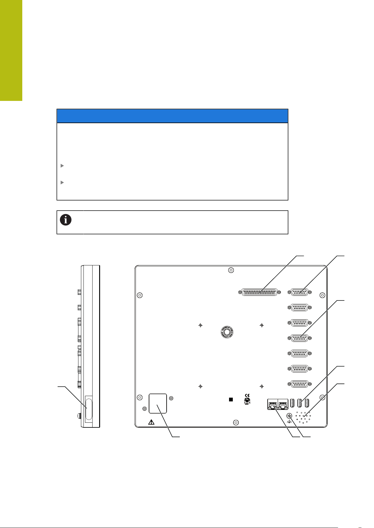
5
HEIDENHAIN
X102 X112
X6
X5
X4
X3
X2
X1
X116
X10 0
X31
AC 100 V ... 240 V
50 Hz .. 60 Hz
(max. 38 W)
X11 7
X32X33 X34
POSITIP 8016
ID 1089176-XX XXX
SN 12 345 678
www.heidenhain.de
1 2
3
4
5
11
12
7
6
Installation | Product overview
5.3 Product overview
The connections on the rear panel of the device are protected by dust protection
caps from contamination and damage.
NOTICE
Contamination or damage may result if the dust protection caps are
missing!
If no dust protection caps are fitted to unused connections, this may impair the
proper functioning of the contacts or destroy them.
Remove dust protection caps only when connecting measuring devices or
peripherals
If you remove a measuring device or peripheral, re-attach the dust protection
cap to the connection
The type of connections for encoders may vary depending on the
product version.
Rear panel without dust protection caps
50
Figure 10: Rear panel of devices with ID 1089176-xx
HEIDENHAIN | POSITIP 8000 | Operating Instructions | 09/2018
Page 51
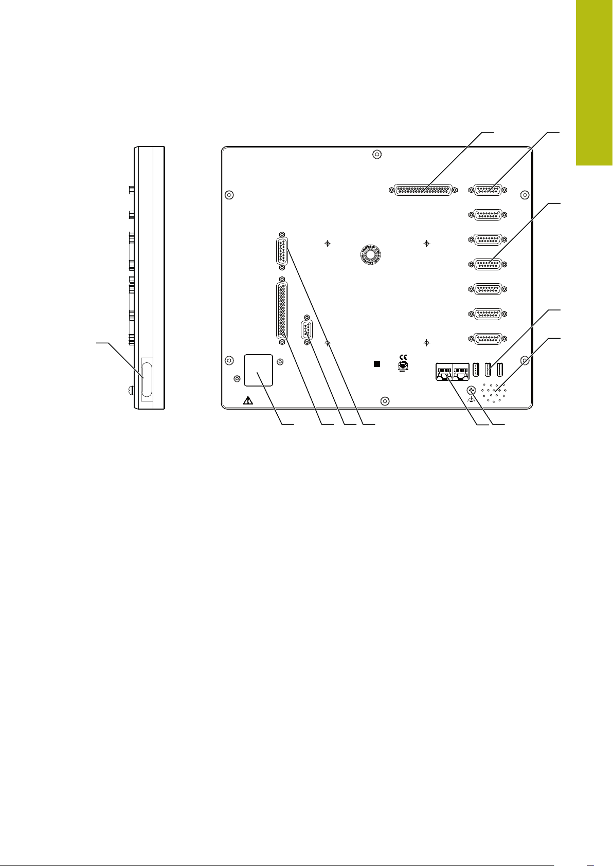
Installation | Product overview
HEIDENHAIN
X102 X112
X6
X5
X4
X3
X2
X1
X116
X104
X31
AC 100 V ... 240 V
50 Hz .. 60 Hz
(max. 79 W)
X105
X106
X11 7
X32X33 X34
POSITIP 8016 ACTIVE
ID 1089177-XX XXX
SN 12 345 678
www.heidenhain.de
X10 0
8
3
4
5
6
1011
12
9
1 2
7
5
Figure 11: Rear panel of devices with ID 1089177-xx
Connections:
1 X10²: 37-pin D-sub connection for digital TTL interface (8 inputs, 16 outputs)
2 X112: 15-pin D-sub connection for touch probes (e.g. HEIDENHAIN touch probe)
3 X1-X6: 15-pin D-sub connections for encoder with interfaces of the type 1 VPP,
11μAPP or EnDat 2.2
Four inputs enabled by default, with option of enabling another two inputs
4 X32-X34: USB 2.0 Hi-Speed connection (Type-A) for printer or USB mass storage
device
5 Speaker
6 Functional ground connection as per IEC/EN 60204-1
7 X116: RJ45 Ethernet connection for communication and data exchange with
downstream systems or PC
X117: Not currently supported
11 X100: Power switch and power connection
Additional connections on devices with ID 1089177-xx:
8 X10⁶: 15-pin D-sub connection for analog interface (4 inputs, 4 outputs)
9 X10⁴: 9-pin D-sub connection for universal relay interface (2x relay changeover
contacts)
10 X105: 37-pin D-sub connection for digital interface (DC 24 V; 24 switching inputs,
8 switching outputs)
Left side panel
12 X31 (under protective cover): USB 2.0 Hi-Speed connection (Type-A) for printer or
USB mass storage device
HEIDENHAIN | POSITIP 8000 | Operating Instructions | 09/2018
51
Page 52

5
Installation | Connecting encoders
5.4 Connecting encoders
For encoders with an EnDat 2.2 interface: If the corresponding encoder
input has already been assigned to an axis in the device settings, then
the encoder is automatically detected upon restart, and the settings are
adapted. Alternatively, you can assign the encoder input after you have
connected the encoder.
Note the following pin layout
Remove and save the dust protection caps
Route the cables depending on the mounting variant
Further information: "Assembly of the product", Page 42
Connect the encoder cables tightly to the respective connections
Further information: "Product overview", Page 50
If the cable connectors include mounting screws, do not overtighten them
Pin layout of X1, X2, X3, X4, X5, X6
1 VPP, 11 µAPP, EnDat 2.2
1 2 3 4 5 6 7 8
1 V
PP
11 μA
EnDat /
A+ B+ / / R– /
I
PP
1+
0 V
I
2+
/
9 10 11 12 13 14 15
1 V
PP
A– B- / R+ /
Sense
0 V
11 μA
PP
EnDat /
I
1-
I
2-
/
U
P
Sense
U
P
/ I
Inter-
0+
nal
DATA
/ I
shield
0+
/ CLOCK
/
DATA / CLOCK
/
52
HEIDENHAIN | POSITIP 8000 | Operating Instructions | 09/2018
Page 53

Installation | Connecting touch probes
5.5 Connecting touch probes
The following touch probes can be connected to the unit:
HEIDENHAIN TS 248 touch probe
HEIDENHAIN KT 130 edge finder
Further information: "Items supplied and accessories", Page 36
Comply with the pin layout
Remove and save the dust protection caps
Route the cables depending on the mounting variant
Further information: "Assembly of the product", Page 42
Connect the touch probe firmly
Further information: "Product overview", Page 50
If the cable connectors include mounting screws, do not overtighten them
5
Pin layout of X112
1 2 3 4 5 6 7 8
LED+ B 5 V B 12 V / DC 12 V DC 5 V / GND
9 10 11 12 13 14 15
/ / TP GND TP / LED–
B – Probe signals, readiness
TP – Touch Probe, normally closed
HEIDENHAIN | POSITIP 8000 | Operating Instructions | 09/2018
53
Page 54

5
Installation | Wiring switching inputs and outputs
5.6 Wiring switching inputs and outputs
WARNING
Hazard when using switching inputs for safety functions!
If switching inputs for mechanical limit switches are used for safety functions,
severe injury or death can result.
Do not use the switching inputs for mechanical limit switches for safety
functions
Depending on the peripherals to be connected, the connection work
may need to be carried out by an electrical specialist.
Example: Safety Extra Low Voltage (SELV) exceeded
Further information: "Personnel qualification", Page 31
The product fulfills the requirements of standard IEC 61010-1 only if the
power to the peripheral devices is supplied from a secondary circuit
with current limitation as per IEC 61010-1
power limitation as per IEC 60950-1
secondary circuit as specified in UL1310.
In place of IEC 61010-1
of standards DIN EN 61010-1, EN 61010-1, UL 61010-1 and CAN/CSAC22.2 No. 61010-1can be used, and, in place of IEC 60950-1
Section 2.5, the corresponding sections of standards DIN EN 60950-1,
EN 60950-1, UL 60950-1, CAN/CSA-C22.2 No. 60950-1 can be applied.
Wire switching inputs and outputs in accordance with the following pin layout
Remove and save the dust protection caps
Route the cables depending on the mounting variant
Further information: "Assembly of the product", Page 42
Connect the connecting cables of the peripherals tightly to their connectors
Further information: "Product overview", Page 50
If the cable connectors include mounting screws, do not overtighten them
The digital or analog inputs and outputs must be assigned in the device
settings of the respective switching function.
3rd Ed.
, Section 9.4, the corresponding sections
3rd Ed.
2nd Ed.
, Section 9.4 or with
, Section 2.5 or from a Class 2
2nd Ed.
,
54
HEIDENHAIN | POSITIP 8000 | Operating Instructions | 09/2018
Page 55

Installation | Wiring switching inputs and outputs
Din 0...7
X102
Pin 22
DC 5 V
Dout 0...15
GND (D)
X102
DC 5 V
TTL
Pin layout of X102
1 2 3 4 5 6 7 8
GND Din 1 Din 3 Din 4 Din 6 GND Dout 0 Dout 2
9 10 11 12 13 14 15 16
Dout 4 GND Dout 6 Dout 8 Dout 10 GND Dout 12 Dout 14
17 18 19 20 21 22 23 24
/ / GND Din 0 Din 2 DC 5 V Din 5 Din 7
25 26 27 28 29 30 31 32
5
GND Dout 1 Dout 3 Dout 5 GND Dout 7 Dout 9 Dout 11
33 34 35 36 37
GND Dout 13 Dout 15 / /
Digital inputs: Digital outputs:
HEIDENHAIN | POSITIP 8000 | Operating Instructions | 09/2018
55
Page 56

5
Installation | Wiring switching inputs and outputs
Pin layout of X104
1 2 3 4 5 6 7 8 9
R-0
NO
CO – Change Over
NO – Normally Open
NC – Normally Closed
Relay outputs:
R-0
NC
/ R-1
NO
R-1
NC
R-0
CO
/ / R-1
CO
56
HEIDENHAIN | POSITIP 8000 | Operating Instructions | 09/2018
Page 57

Installation | Wiring switching inputs and outputs
Din 0...23
X105
GND
DC 24 V
Dout 0...7
GND
Pin 17, 18, 36
X105
DC 24 V
Pin layout of X 105
1 2 3 4 5 6 7 8
Din 0 Din 2 Din 4 Din 6 Din 8 Din 10 Din 12 Din 14
9 10 11 12 13 14 15 16
Din 16 Din 18 Din 20 Din 22 Dout 0 Dout 2 Dout 4 Dout 6
17 18 19 20 21 22 23 24
DC 24 V DC 24 V GND Din 1 Din 3 Din 5 Din 7 Din 9
25 26 27 28 29 30 31 32
5
Din 11 Din 13 Din 15 Din 17 Din 19 Din 21 Din 23 Dout 1
33 34 35 36 37
Dout 3 Dout 5 Dout 7 DC 24 V GND
Digital inputs: Digital outputs:
HEIDENHAIN | POSITIP 8000 | Operating Instructions | 09/2018
57
Page 58

5
Installation | Wiring switching inputs and outputs
Pin layout of X 106
1 2 3 4 5 6 7 8
Aout 0+ Aout 1+ Aout 2+ Aout 3+ GND GND Ain 1 Ain 3
9 10 11 12 13 14 15
Aout 0– Aout 1– Aout 2– Aout 3– DC 5 V Ain 0 Ain 2
Analog inputs: Analog outputs:
58
HEIDENHAIN | POSITIP 8000 | Operating Instructions | 09/2018
Page 59

Installation | Connecting a printer
4
3 2 1
1 2 3 4 5 6 7 8
5.7 Connecting a printer
Connecting a USB printer
Comply with the pin layout
Remove and save the dust protection caps
Route the cables based on the mounting variant
Further information: "Assembly of the product", Page 42
Connect USB printer to USB Type-A port (X31, X32, X33, X34). Make sure the
USB cable connector is fully inserted
Further information: "Product overview", Page 50
Pin layout X31, X32, X33, X34
5
1 2 3 4
DC 5 V Data (–) Data (+) GND
Connecting an Ethernet printer
Note the following pin layout
Remove and save the dust protection caps
Route the cables based on the mounting variant
Further information: "Assembly of the product", Page 42
Connect the Ethernet printer to the Ethernet port X116 using a standard CAT.5
cable. The cable connector must firmly engage in the port
Further information: "Product overview", Page 50
Pin layout of X116
1 2 3 4 5 6 7 8
D1+
(TX+)
D1–
(TX–)
D2+
(RX+)
D3+ D3– D2–
(RX–)
D4+ D4–
HEIDENHAIN | POSITIP 8000 | Operating Instructions | 09/2018
59
Page 60

5
4
3 2 1
1 2 3 4 5 6 7 8
Installation | Connecting input devices
5.8 Connecting input devices
Comply with the pin layout
Remove and save the dust protection caps
Route the cables based on the mounting variant
Further information: "Assembly of the product", Page 42
Connect USB mouse or USB keyboard to USB Type-A port (X31, X32, X33,
X34). Make sure the USB cable connector is fully inserted
Further information: "Product overview", Page 50
Pin layout X31, X32, X33, X34
1 2 3 4
DC 5 V Data (–) Data (+) GND
5.9 Connecting a network peripheral
Note the following pin layout
Remove and save the dust protection caps
Route the cables depending on the mounting variant
Further information: "Assembly of the product", Page 42
Connect the network peripheral to Ethernet port X116 using a standard CAT.5
cable. The cable connector must firmly engage in the port
Further information: "Product overview", Page 50
Pin layout of X116
1 2 3 4 5 6 7 8
D1+
(TX+)
D1–
(TX–)
D2+
(RX+)
D3+ D3– D2–
D4+ D4–
(RX–)
60
HEIDENHAIN | POSITIP 8000 | Operating Instructions | 09/2018
Page 61

Installation | Connecting the line voltage
5.10 Connecting the line voltage
WARNING
Risk of electric shock!
Improper grounding of electrical devices may result in serious personal injury or
death by electric shock.
Always use 3-wire power cables
Make sure the ground wire is correctly connected to the ground of the
building's electrical installations
WARNING
Fire hazard due to wrong power cable!
5
Use of a power cable that does not meet the requirements of the mounting
location may cause a fire hazard.
Use only a power cable that meets at least the national requirements of the
respective country in which the product is mounted
Comply with the pin layout
Connect the power connection to a 3-wire grounded power outlet using a
power cable that meets requirements
Further information: "Product overview", Page 50
Pin layout X100
1 2 3
L/N N/L
HEIDENHAIN | POSITIP 8000 | Operating Instructions | 09/2018
61
Page 62

Page 63

6
Basic operation
Page 64

6
Basic operation | Overview
6.1 Overview
This chapter describes the user interface, operating elements, and basic functions
of the unit.
6.2 Using the touchscreen and input devices
6.2.1 Touchscreen and input devices
The operating elements on the user interface of the unit are operated via a
touchscreen or a connected USB mouse.
To enter data, you can use the screen keyboard of the touchscreen or a connected
USB keyboard.
NOTICE
Malfunctions of the touchscreen caused by humidity or contact with
water!
Humidity or water can impair the proper functioning of the touchscreen.
Protect the touchscreen from humidity or contact with water
Further information: "Product data", Page 376
64
HEIDENHAIN | POSITIP 8000 | Operating Instructions | 09/2018
Page 65

Basic operation | Using the touchscreen and input devices
6.2.2 Gestures and mouse actions
To activate, switch or move the operating elements of the user interface, you
can use the unit's touchscreen or a mouse. Gestures are used to operate the
touchscreen and the mouse.
The gestures for operating the touchscreen may differ from the
gestures for operating the mouse.
If the gestures for operating the touchscreen differ from those for
operating the mouse, then these instructions describe both operating
options as alternative actions.
The alternative actions for operating the touchscreen or the mouse are
identified by the following symbols:
Operation using the touchscreen
Operation using the mouse
6
The following overview describes the different gestures for operating the
touchscreen or the mouse:
Tapping
Means touching the screen briefly with your fingertip
Means pressing the left mouse button once
The actions initiated by tapping include
Selection of menus, features or parameters
Entering characters with the screen keyboard
Closing dialogs
Holding (long press)
Means touching the screen and holding your finger(s) on it for a
few seconds
Means pressing the left mouse button once and holding it
down
The actions initiated by holding are
Quickly changing the values in input fields with plus and
minus buttons
HEIDENHAIN | POSITIP 8000 | Operating Instructions | 09/2018
65
Page 66

6
Basic operation | Using the touchscreen and input devices
Dragging
Is a combination of long press and then swipe, moving a finger
over the touchscreen when at least the starting point of motion
is defined
Means pressing the left mouse button once and holding it
down while moving the mouse; at least the starting point of the
motion is defined
The actions initiated by dragging include
Scrolling through lists and texts
66
HEIDENHAIN | POSITIP 8000 | Operating Instructions | 09/2018
Page 67

Basic operation | General operating elements and functions
6.3 General operating elements and functions
The operating elements described below are available for configuration and
operating the product via the touchscreen or input devices.
Screen keyboard
With the screen keyboard, you can enter text into the input fields of the user
interface. The displayed screen keyboard is either numeric or alphanumeric,
depending on the input field.
6
Figure 12: Screen keyboard
To enter values, tap an input field
The input field is highlighted
The screen keyboard is displayed
Enter text or numbers
In some input fields, a green check mark indicates that the entry is correct
If the entry is incomplete or incorrect, a red exclamation mark is displayed. The
entry cannot be concluded in this case
To apply the values, confirm the entry with RET
The values are displayed
The screen keyboard disappears
Input fields with plus and minus buttons
To adjust a numerical value, use the + (plus) and – (minus) buttons to the left and
right of the numerical value.
Tap + or – until the desired value is displayed
Long-press + or – to scroll through the values more
quickly
The selected value is displayed
HEIDENHAIN | POSITIP 8000 | Operating Instructions | 09/2018
67
Page 68

6
Basic operation | General operating elements and functions
Toggle switch
Use the toggle switch to switch between functions.
Tap the desired function
The active function is shown in green
The inactive function is shown in light gray
Slide switch
With the sliding switch, you can activate or deactivate a function.
Drag the sliding switch to the desired position or tap the
sliding switch
The function is activated or deactivated
Drop-down list
Buttons that open drop-down lists are indicated by a triangle pointing down.
Tap the button
The drop-down list opens
The active entry is highlighted in green
Tap the desired entry
The selected entry is applied
Undo
With this button, you can undo the last action.
Processes that have already been concluded cannot be undone.
Tap Undo
The last action is undone
Add
To add a feature, tap Add
The new feature is added
Close
Tap Close to close a dialog
68
Confirm
Tap Confirm to conclude an activity
Back
Tap Back to return to the higher level in the menu
structure
HEIDENHAIN | POSITIP 8000 | Operating Instructions | 09/2018
Page 69

Basic operation | POSITIP 8000 – switch-on and switch-off
6.4 POSITIP 8000 – switch-on and switch-off
6.4.1 Switching on POSITIP 8000
Before using the product, you need to perform the commissioning
and setup steps. Depending on the purpose of use, you may have to
configure additional setup parameters.
Further information: "Commissioning", Page 103
Turn the power switch on
The power switch is on the rear side of the unit
The unit powers up. This can take a moment
If automatic user login is active and the last user who logged in was of the
Operator type, the user interface opens with the Manual operation menu
If automatic user login is not active, the User login menu is displayed
Further information: "User login and logout", Page 70
6
6.4.2 Activating and deactivating the energy saving mode
If you will not be using the unit for a while, you should activate the energy-saving
mode. This switches the unit to an inactive state without interrupting the power
supply. The screen is switched off in this state.
Activating energy-saving mode
Tap Switch off in the main menu
Tap Energy-saving mode
The screen switches off
Deactivating energy-saving mode
Tap anywhere on the touchscreen
An arrow appears at the bottom of the screen
Drag the arrow up
The screen is switched on and shows the user interface last
displayed
HEIDENHAIN | POSITIP 8000 | Operating Instructions | 09/2018
69
Page 70

6
Basic operation | POSITIP 8000 – switch-on and switch-off
6.4.3 Switching off POSITIP 8000
NOTICE
Damage to the operating system!
Disconnecting the power source while the product is on can damage the
operating system of the product.
Use the Switch-off menu to shut down the product
Do not disconnect the power source while the product is on
Do not turn the power switch off until the product has shut down
Tap Switch off in the main menu
Tap Shut down
The operating system shuts down
Wait until the following message appears on the screen:
You can switch off the device now.
Turn the POSITIP 8000 off at the power switch
6.5 User login and logout
In the User login menu, you can log in and out of the product as a user.
Only one user can be logged in to the product at a time. The logged-in user is
displayed. Before a new user can log in, the logged-in user has to log out.
The product provides various authorization levels that grant the user full
or restricted access to management and operation functionality.
70
HEIDENHAIN | POSITIP 8000 | Operating Instructions | 09/2018
Page 71

Basic operation | User login and logout
6.5.1 User login
Tap User login in the main menu
Select the user in the drop-down list
Tap the Password input field
Enter the user's password
Further information: "Logging in for Quick Start", Page 179
If the password does not match the default
password, ask a Setup user or OEM user for the
assigned password.
If the password is no longer known, contact a
HEIDENHAIN service agency.
Confirm entry with RET
Tap Log in
The user is logged in and the Manual operation menu is
displayed
6
6.5.2 User logout
Tap User login in the main menu
Tap Log out
The user is logged out
All functions of the main menu are inactive, except for Switch
off
The product can only be used again after a user has logged in
6.6 Setting the language
The default language for the user interface is English. You can switch the user
interface to the desired language.
Tap Settings in the main menu
Tap User
The logged-in user is indicated by a check mark
Select the logged-in user
The language selected for the user is indicated by a national
flag in the Language drop-down list
Select the flag for the desired language in the Language
drop-down list
The user interface is displayed in the selected language
HEIDENHAIN | POSITIP 8000 | Operating Instructions | 09/2018
71
Page 72

6
Basic operation | Performing the reference mark search after startup
6.7 Performing the reference mark search after startup
If the unit is configured with the Turning application mode and a
spindle axis S, then you must define an upper limit for the spindle
speed prior to a possible machining operation.
Further information: "Defining the upper limit for the spindle speed (in
the Turning application mode)", Page 223
If the reference mark search after unit start is active, then all of the
unit’s functions will be disabled until the reference mark search has
been successfully completed.
Further information: "Reference marks (Encoder)", Page 336
The reference mark search does not need to be performed for serial
encoders with EnDat interface, because the axes are automatically
homed.
If the reference mark search is active on the unit, then a wizard will ask you to
traverse the reference marks of the axes.
After logging in, follow the instructions of the wizard
The Reference symbol stops blinking upon successful completion of the
reference mark search
Further information: "Operating elements of the position display", Page 88
Further information: "Activating the reference mark search", Page 115
6.8 User interface
The unit is available in different versions, which are variously equipped.
The user interface and available functions may vary depending on the
version.
72
HEIDENHAIN | POSITIP 8000 | Operating Instructions | 09/2018
Page 73

Basic operation | User interface
6.8.1 User interface after switch-on
Factory default user interface
The illustration shows the user interface the way it looks when you switch on the
product for the first time.
This user interface will also be displayed after resetting the product to the factory
defaults.
6
Figure 13: The user interface in the product’s factory default setting
User interface after startup
If automatic user login is active and the last user who logged in was of the
Operator type, the Manual operation menu is displayed after the product has
started up.
Further information: "Manual operation menu", Page 76
If automatic user login is not active, the product opens the User login menu.
Further information: "User login menu", Page 86
HEIDENHAIN | POSITIP 8000 | Operating Instructions | 09/2018
73
Page 74

6
1
2
3
Basic operation | User interface
6.8.2 Main menu of the user interface
User interface (in Manual operation mode)
Figure 14: User interface (in Manual operation mode)
1
Message display area, displays the time and the number of unclosed messages
2
Main menu with operating elements
Operating elements of the main menu
The main menu is displayed independently of activated software options.
Operating
element
Function
Message
Display of an overview of all messages as well as the
number of messages that have not been closed
Further information: "Messages", Page 100
Manual operation
Manual positioning of machine axes
Further information: "Manual operation menu",
Page 76
MDI mode
Direct input of the desired axis movements (Manual Data
Input); the distance-to-go is calculated and displayed
Further information: "MDI menu", Page 78
Program run
Execution of a previously created program with operator
74
guidance
Further information: "Program run menu", Page 81
Programming
Creation and management of individual programs
Further information: "Programming menu", Page 82
HEIDENHAIN | POSITIP 8000 | Operating Instructions | 09/2018
Page 75

Basic operation | User interface
6
Operating
element
Function
File management
Management of the files that are available on the product
Further information: "File management menu",
Page 85
User login
Login and logout of the user
Further information: "User login menu", Page 86
Settings
Settings of the product, such as setting up users, configuring sensors or updating the firmware
Further information: "Settings menu ", Page 87
Switch-off
Shutdown of the operating system or activation of energysaving mode
Further information: "Switch-off menu", Page 88
HEIDENHAIN | POSITIP 8000 | Operating Instructions | 09/2018
75
Page 76

6
1
4
2
5
3
Basic operation | User interface
6.8.3 Manual operation menu
Activation
Tap Manual operation in the main menu
The user interface for manual operation is displayed
Manual operation menu (in the Milling application mode)
Figure 15: Manual operation menu in the milling application mode
1
Axis key
2
Reference
3
Position display
4
Status bar
5
Spindle speed (machine tool)
76
HEIDENHAIN | POSITIP 8000 | Operating Instructions | 09/2018
Page 77

Basic operation | User interface
1
5
4
32
Manual operation menu (in the Turning application mode)
6
Figure 16: Manual operation menu in the turning application mode
1
Axis key
2
Reference
3
Position display
4
Status bar
5
Spindle speed (machine tool)
In the Manual operation menu, the workspace shows the position values
measured at the machine axes.
The status bar provides auxiliary functions.
Further information: "Milling Manual operation", Page 211
Further information: "Turning Manual operation", Page 221
HEIDENHAIN | POSITIP 8000 | Operating Instructions | 09/2018
77
Page 78

6
1
3
2
4
5
Basic operation | User interface
6.8.4 MDI menu
Activation
Tap MDI in the main menu
MDI mode menu (in the Milling application mode)
Figure 17: MDI mode menu in the milling application mode
1
Axis key
2
Actual position
3
Distance-to-go
4
Status bar
5
Spindle speed (machine tool)
78
HEIDENHAIN | POSITIP 8000 | Operating Instructions | 09/2018
Page 79

Basic operation | User interface
1
4
2
5
6
3
MDI mode menu (in the Turning application mode)
6
Figure 18: MDI mode menu in the turning application mode
1
Axis key
2
Actual position
3
Coupled axes
4
Distance-to-go
5
Status bar
6
Spindle speed (machine tool)
HEIDENHAIN | POSITIP 8000 | Operating Instructions | 09/2018
79
Page 80

6
1
32
4
5
Basic operation | User interface
MDI block dialog
Tap MDI in the main menu
Tap Create on the status bar
The user interface for the MDI mode is displayed
Figure 19: MDI block dialog
1
View bar
2
Block parameters
3
MDI block
4
Status bar
5
Block tools
The MDI (Manual Data Input) menu enables you to enter the desired axis
movements directly. You specify the distance to the target point, and the distance
to go is then calculated and displayed.
The status bar provides additional measured values and functions.
Further information: "Milling MDI mode", Page 229
Further information: "Turning MDI mode", Page 241
80
HEIDENHAIN | POSITIP 8000 | Operating Instructions | 09/2018
Page 81

Basic operation | User interface
1
2
5
3
4
6.8.5 Program run menu
Activation
Tap Program run in the main menu
The user interface for program run is displayed
Program run menu (in the Milling application mode)
6
Figure 20: Program run menu in the milling application mode
1
View bar
2
Status bar
3
Program control
4
Spindle speed (machine tool)
5
Program management
HEIDENHAIN | POSITIP 8000 | Operating Instructions | 09/2018
81
Page 82

6
1
2
5
3
4
Basic operation | User interface
Program run menu (in the Turning application mode)
Figure 21: Program run menu in the turning application mode
1
View bar
2
Status bar
3
Program control
4
Spindle speed (machine tool)
5
Program management
The Program run menu makes it possible to execute a program that has
previously been created in the Programming operating mode. During execution, a
wizard will guide you through the individual program steps.
You can display a visualization of the selected block in the optional simulation
window.
The status bar provides additional measured values and functions.
Further information: "Milling Program run", Page 251
Further information: "Turning Program run", Page 259
6.8.6 Programming menu
Activation
Tap Programming in the main menu
The user interface for programming is displayed
82
The status bar and the optional OEM bar are not available in the
Programming menu.
HEIDENHAIN | POSITIP 8000 | Operating Instructions | 09/2018
Page 83

Basic operation | User interface
1
2
3
1
4
2
5
3
6
Programming menu (in the Milling application mode)
6
Figure 22: Programming menu in the milling application mode
1
View bar
2
Toolbar
3
Program management
You can display a visualization of the selected block in the optional simulation
window.
Figure 23: Programming menu with simulation window opened
1
View bar
2
Simulation window (optional)
3
Block parameters
4
Toolbar
5
Program blocks
6
Program management
HEIDENHAIN | POSITIP 8000 | Operating Instructions | 09/2018
83
Page 84

6
1
2
3
1
4
2
5
3
6
Basic operation | User interface
Programming menu (in the Turning application mode)
Figure 24: Programming menu in the turning application mode
1
View bar
2
Toolbar
3
Program management
You can display a visualization of the selected block in the optional simulation
window.
84
Figure 25: Programming menu with simulation window opened
1
View bar
2
Simulation window (optional)
3
Block parameters
4
Toolbar
5
Program blocks
6
Program management
HEIDENHAIN | POSITIP 8000 | Operating Instructions | 09/2018
Page 85

Basic operation | User interface
1
2
In the Programming menu, you can create and manage programs. You define
individual machining steps or machining patterns as blocks. A sequence of blocks
then forms a program.
Further information: "Milling Programming", Page 269
Further information: "Turning Programming", Page 281
6.8.7 File management menu
Activation
Tap File management in the main menu
The user interface for file management is displayed
Short description
6
Figure 26: File management menu
1
List of available storage locations
2
List of folders in the selected storage location
The File management menu shows an overview of the files stored in the
product's memory.
If USB mass storage devices (FAT32 format) are connected or network drives
are available, they are displayed in the list of storage locations. The USB mass
storage devices and the network drives are displayed with their names or drive
designations.
Further information: "File management", Page 293
HEIDENHAIN | POSITIP 8000 | Operating Instructions | 09/2018
85
Page 86

6
1
2
Basic operation | User interface
6.8.8 User login menu
Activation
Tap User login in the main menu
The user interface for user login and logout is displayed
Short description
Figure 27: User login menu
1
Display of the logged-in user
2
User login
The User login menu shows the logged-in user in the column on the left. The login
of a new user is displayed in the column on the right.
To log in another user, the logged-in user must log out.
Further information: "User login and logout", Page 70
86
HEIDENHAIN | POSITIP 8000 | Operating Instructions | 09/2018
Page 87

Basic operation | User interface
1
2
6.8.9 Settings menu
Activation
Tap Settings in the main menu
The user interface for the device settings is displayed
Short description
6
Figure 28: Settings menu
1
List of setting options
2
List of setting parameters
The Settings menu shows all options for configuring the product. With the setting
parameters, you can adapt the product to on-site requirements.
Further information: "Settings", Page 301
The product provides various authorization levels that grant the user full
or restricted access to management and operation functionality.
HEIDENHAIN | POSITIP 8000 | Operating Instructions | 09/2018
87
Page 88

6
X
X
R
Basic operation | User interface
6.8.10 Switch-off menu
Activation
Tap Switch off in the main menu
The operating elements for shutting down the operating
system, for activating the energy-saving mode and for
activating the cleaning mode are displayed
Short description
The Switch off menu provides the following options:
Operating
element
Further information: "POSITIP 8000 – switch-on and switch-off", Page 69
Further information: "", Page 360
Function
Shut down
Shuts down the operating system
Energy saving mode
Switches the screen off and puts the operating system into
energy-saving mode
Cleaning mode
Switches the screen off; the operating system continues
unchanged
6.9 Position display
The unit’s position display shows the axis positions and additional information
about the configured axes (if applicable).
You can also couple the display of axes and have access to the spindle functions.
6.9.1 Operating elements of the position display
Symbol Meaning
Axis key
Axis key functions:
Tapping the axis key: opens input field for position value
(Manual mode) or dialog MDI block (MDI mode)
Holding down the axis key: sets the current position as zero
point
Dragging the axis key to the right: opens menu if functions
are available for the axis
In the turning application mode: The position display shows the
diameter of the radial machining axis X
Further information: "Display", Page 305
Reference mark search performed successfully
88
HEIDENHAIN | POSITIP 8000 | Operating Instructions | 09/2018
Page 89

Basic operation | Position display
R
+Z
1
Symbol Meaning
Reference mark search not performed or no reference mark
detected
Zo axis is coupled with the Z axis. Position display shows the
sum of both position values
Further information: "Coupling of axes (in the Turning applica-
tion mode)", Page 89
Z axis is coupled with the Zo axis. Position display shows the
sum of both position values
Selected gear stage of the gear spindle
Further information: "Setting the gear stage for gear spindles",
Page 91
Spindle speed cannot be achieved with selected gear stage
Select a higher gear stage
6
Spindle speed cannot be achieved with selected gear stage
Select a lower gear stage
The CSS (constant surface speed) spindle mode is activated
Further information: "Setting the spindle mode (in the Turning
application mode)", Page 92
If the icon is flashing, then the calculated spindle speed lies
outside of the defined speed range. The desired surface speed
cannot be attained. The spindle will continue to turn at the
maximum or minimum speed
In MDI mode and Program Run , a scaling factor is applied to
the axis
Further information: "Adjusting settings in the quick access
menu", Page 94
Axis is feedback-controlled
6.9.2 Position display functions
Coupling of axes (in the Turning application mode)
In the Turning application mode, you can alternately couple the display of the Z
axis and the Zo axis. For coupled axes, the position display shows the sum of the
position values of both axes.
If the Z axis and the Zo axis have been coupled, the Program run
operating mode is disabled.
Coupling is identical for the Z axis and Zo axis. The following describes
only the coupling of the Z axis.
HEIDENHAIN | POSITIP 8000 | Operating Instructions | 09/2018
89
Page 90

6
Z
+Z
Z
Basic operation | Position display
Coupling axes
In the working space, drag the Z axis key to the right
Tap Couple
The Zo axis is now coupled with the Z axis
The icon for the coupled axes is shown next to the Z axis key
The position value for the coupled axes is shown as a sum
Decoupling axes
In the working space, drag the Z axis key to the right
Tap Decouple
The position value of both axes are shown independently of
each other
Setting the spindle speed
You can control the spindle speed depending on the configuration of the
connected machine tool.
Tap or long-press + or – to set the spindle speed to the
desired value
or
Tap the Spindle speed input field, enter the value and tap
RET to confirm
The product applies the entered spindle speed as the
nominal value and controls the spindle of the machine tool
accordingly
90
HEIDENHAIN | POSITIP 8000 | Operating Instructions | 09/2018
Page 91

Basic operation | Position display
S
1
Setting the gear stage for gear spindles
If your machine tool uses a gear spindle, then you can select the gear stage used.
The selection of the gear stages can also be controlled via an external
signal.
Further information: "Spindle axis S", Page 341
In the working space, drag the S axis key to the right
Tap Gear stage
The Set gear stage dialog appears
Tap the desired gear stage
Tap Confirm
The selected gear stage is now adopted as the new value
Drag the S axis key to the left
The icon for the selected gear stage appears next to the S
axis key
6
If the desired spindle speed cannot be attained with the selected gear
stage, then the gear stage icon will flash with an upward pointing arrow
(higher gear stage) or with a downward pointing arrow (lower gear
stage).
HEIDENHAIN | POSITIP 8000 | Operating Instructions | 09/2018
91
Page 92

6
S
S
Basic operation | Position display
Setting the spindle mode (in the Turning application mode)
In the Turning application mode, you can decide whether the unit uses the
standard speed mode or CSS (constant surface speed) for the spindle mode.
In the CSS spindle mode, the unit calculates the spindle speed such that the
surface speed of the turning tool remains constant regardless of the workpiece
geometry.
Activating the CSS spindle mode
In the working space, drag the S axis key to the right
Tap CSS mode
The Activate CSS dialog appears
Enter the value for Maximum spindle speed
Tap Confirm
The CSS spindle mode is activated
The spindle speed is shown in the unit of measure m/min
Drag the S axis key to the left
The icon for the CSS spindle mode appears next to the S axis
key
Activating the speed mode
In the working space, drag the S axis key to the right
Tap Speed mode
The Activate speed mode dialog appears
Enter the value for Maximum spindle speed
Tap Confirm
The speed mode is activated
The spindle speed is shown in the unit of measure rpm
Drag the S axis key to the left
92
HEIDENHAIN | POSITIP 8000 | Operating Instructions | 09/2018
Page 93

Basic operation | Status bar
6.10 Status bar
The status bar and the optional OEM bar are not available in the
Programming menu.
The status bar displays the feed rate and the traversing speed. The operating
elements of the status bar also give you direct access to the preset table and tool
table, as well as to the stopwatch and calculator features.
6.10.1 Operating elements of the status bar
The status bar provides the following operating elements:
6
Operating
element
Function
Quick access menu
For setting the units of measure for linear and angular
values, configuring a scaling factor, and configuring the
position display for radial machining axes (in the Turning
application mode); tapping it opens the quick access menu
Further information: "Adjusting settings in the quick
access menu", Page 94
Preset table
Display of the current preset; tapping opens the preset
table
Further information: "Creating a preset table", Page 168
Tool table
Display of the current tool; tapping opens the tool table
Further information: "Creating a tool table", Page 164
Stopwatch
Time display with Start / Stop function in h:mm:ss format
Further information: "Stopwatch", Page 95
Calculator
Calculator with the most important mathematical functions,
speed calculator, and taper calculator
Further information: "Calculator", Page 96
Feed rate
Display of the actual feed rate of the currently fastest axis
The feed-rate value can be set in the Manual operation and
MDI operating modes; tapping it opens the feed-rate menu
HEIDENHAIN | POSITIP 8000 | Operating Instructions | 09/2018
93
Page 94

6
X
Basic operation | Status bar
Operating
element
Function
Override
Display of the changed traversing speed of an axis. The
change is made using an external controller on an NCcontrolled machine tool
Auxiliary functions
Auxiliary functions in Manual operation mode, depending
on the configured application mode
Further information: "Auxiliary functions in Manual
operation mode", Page 97
MDI block
For creating machining blocks in MDI mode
6.10.2 Adjusting settings in the quick access menu
With the quick access menu, you can adjust the following settings:
Unit for linear values (Millimeters or Inch
Unit for angular values (Radian, Decimal degrees or Deg-Min-Sec)
The display of Radial machining axes (Radius or Diameter)
The Scaling factor by which the stored position is multiplied during execution
of an MDI block or program block
Feed-rate value for axes in the Manual operation and MDI operating modes
Setting the units of measure
Tap the quick access menu on the status bar
Select the desired Unit for linear values
Select the desired Unit for angular values
Tap Close to close the quick access menu
The selected units are displayed in the quick access menu
Activating the display of Radial machining axes
Tap the quick access menu on the status bar
Select the desired option
Tap Close to close the quick access menu
If the Diameter option is selected, then the corresponding
icon appears in the position display
94
HEIDENHAIN | POSITIP 8000 | Operating Instructions | 09/2018
Page 95

Basic operation | Status bar
Activating the Scaling factor
The Scaling factor is multiplied by the position stored in the block during execution
of an MDI block or program block. This allows you to mirror or scale an MDI block
or program block on one or more axes, without changing the block.
6
Tap the quick access menu on the status bar
To navigate to the desired setting, drag the view to the left
Activate Scaling factor with the ON/OFF sliding switch
Enter the desired Scaling factor for every axis
Confirm each entry with RET
Tap Close to close the quick access menu
For an active scaling factor ≠ 1, the corresponding icon
appears in the position display
Specifying the feed-rate value
In the Manual operation and MDI operating modes, you can set the feed-rate value
for the axes in mm/min; in the Turning application mode, you can also set it in
mm/rev.
6.10.3 Stopwatch
The status bar provides a stopwatch for measuring the machining times, etc.
The stopwatch uses the time display format h:mm:ss and operates on the same
principle as a standard stopwatch, i.e. it measures elapsed time.
Operating element Function
Tap Feed rate on the status bar
The Feed ratedialog appears
In the Milling application mode: Enter the feed rate in mm/
min
If required, in the Turning application mode: Enter the feed
rate in mm/rev
Tap Close to close the dialog
The axes are moved at the entered feed rate.
Start
Starts time measurement or resumes time measurement after Pause
Pause
Interrupts time measurement
Stop
Stops time measurement and resets it to 0:00:00
HEIDENHAIN | POSITIP 8000 | Operating Instructions | 09/2018
95
Page 96

6
Basic operation | Status bar
6.10.4
Calculator
For the purpose of calculations, the unit’s standard features in the status bar
include a calculator with the most important mathematical functions. You can also
select a speed calculator and taper calculator. To enter the numeric values, use the
numeric keys as on a normal computer.
Calculator Function Application
mode
Standard
Contains the most important mathematical functions
Speed calculator
Enter the Diameter (mm) and Cutting speed (m/min)
in the provided fields
The speed is calculated automatically
Taper calculator
Enter D1, D2, and L in the provided fields
The angle is automatically calculated
The taper is graphically displayed
Milling
Turning
Milling
Turning
Turning
96
HEIDENHAIN | POSITIP 8000 | Operating Instructions | 09/2018
Page 97

Basic operation | Status bar
6.10.5 Auxiliary functions in Manual operation mode
Depending on the configured application mode, the following operating elements
are available:
6
Operating
element
Function
Reference marks
For starting the reference mark search
Further information: "Activating the reference mark
search", Page 115
Probing
For probing the edge of a workpiece
Further information: "Defining presets", Page 214
Probing
For finding the centerline of a workpiece
Further information: "Defining presets", Page 214
Probing
For finding the center point of a circular feature (hole or
cylinder)
Further information: "Defining presets", Page 214
Presets
For setting presets
Further information: "Presetting by probing (in the Turning
application mode)", Page 171
Tool data
For tool setting (touch-off)
Further information: "Setting the tool (in the Turning
application mode)", Page 166
HEIDENHAIN | POSITIP 8000 | Operating Instructions | 09/2018
97
Page 98

6
Basic operation | OEM bar
6.11 OEM bar
The status bar and the optional OEM bar are not available in the
Programming menu.
The optional OEM bar allows you to control the configuration of the functions of
the connected machine tool, independently of its configuration.
6.11.1
Operating elements of the OEM bar
The operating elements that are available on the OEM bar depend on
the configuration of the device and of the connected machine tool.
Further information: "Configuring the OEM bar", Page 130
The OEM bar usually provides the following operating elements:
Operating
element
Function
Logo
Displays the configured OEM logo
Spindle speed
Displays one or more values that have been predefined for
the spindle speed of a connected NC-controlled machine
tool
Further information: "Configuring nominal values for the
spindle speed", Page 131
98
HEIDENHAIN | POSITIP 8000 | Operating Instructions | 09/2018
Page 99

Basic operation | OEM bar
6
6.11.2
Calling functions of the OEM bar
The operating elements that are available on the OEM bar depend on
the configuration of the device and of the connected machine tool.
Further information: "Configuring the OEM bar", Page 130
The operating elements in the OEM bar allow you to control special functions (e.g.,
spindle functions).
Further information: "Configuring special functions", Page 133
Setting spindle speed
Tap the Spindle speed field on the OEM bar
The product applies the predefined voltage value at which
the spindle of the connected machine tool is brought to the
selected rotational speed (with no load on the spindle)
Programming spindle speed
Tap or long-press + or – to bring the spindle to the desired
rotational speed
Long-press the desired Spindle speed field on the OEM bar
The background color of the field is highlighted in green
The product applies the current spindle speed as the nominal
value and displays it in the Spindle speed field
HEIDENHAIN | POSITIP 8000 | Operating Instructions | 09/2018
99
Page 100

6
1
2
3
Basic operation | Messages and audio feedback
6.12 Messages and audio feedback
6.12.1 Messages
Figure 29: Display of messages in the workspace
1
Message display area
2
Message list
The messages that appear at the top of the workspace are generated as a result of
e.g. operator errors or uncompleted processes.
The messages are displayed on occurrence of the message cause or when you tap
the Messages display area at the top left of the screen.
Viewing messages
Tap Messages
The message list opens
Resizing the display area
To resize the message display area, drag the handle up or
down
To close the display area, drag the handle up out of the
screen
The number of unclosed messages is indicated in Messages
100
HEIDENHAIN | POSITIP 8000 | Operating Instructions | 09/2018
 Loading...