

User’s Manual
HEIDENHAIN
Conversational
Programming
iTNC 530
NC software
606 420-02
606 421-02
606 424-02
English (en)
12/2011
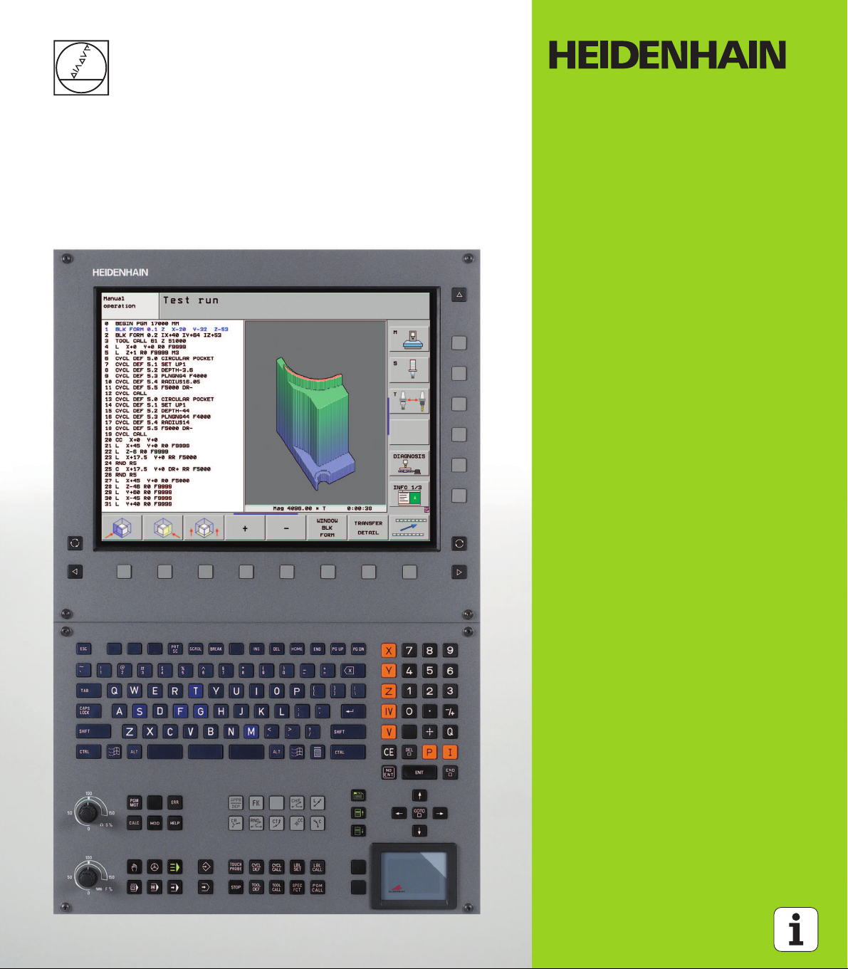
Controls of the TNC
1
50
0
50
100
F %
1
50
0
50
100
S %
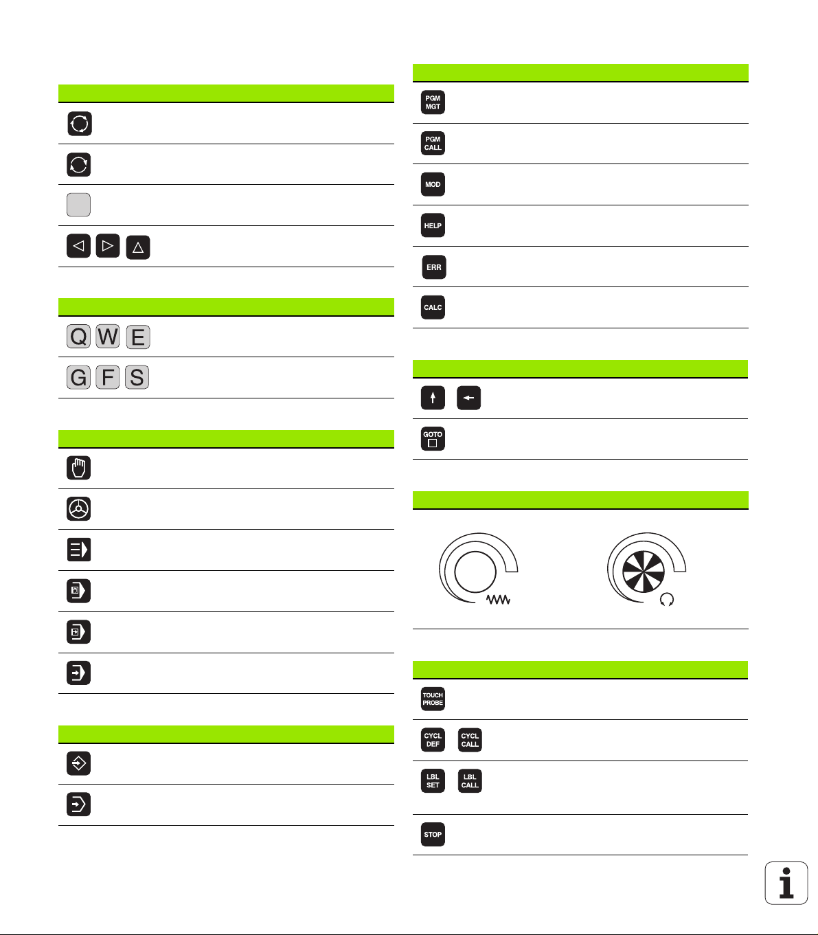
Keys on visual display unit
Key Function
Split screen layout
Toggle the display between machining
and programming modes
Soft keys for selecting functions on
screen
Shifts between soft-key rows
Alphanumeric keyboard
Key Function
File names, comments
DIN/ISO programming
Machine operating modes
Key Function
Manual Operation
Electronic Handwheel
Program/file management, TNC functions
Key Function
Select or delete programs and files,
external data transfer
Define program call, select datum and
point tables
Select MOD functions
Display help text for NC error messages,
call TNCguide
Display all current error messages
Show calculator
Navigation keys
Key Function
Move highlight
Go directly to blocks, cycles and
parameter functions
Potentiometer for feed rate and spindle speed
Feed rate Spindle speed
Programming modes
Key Function
smarT.NC
Positioning with Manual Data Input
Program Run, Single Block
Program Run, Full Sequence
Programming and Editing
Test Run
Cycles, subprograms and program section repeats
Key Function
Define touch probe cycles
Define and call cycles
Enter and call labels for
subprogramming and program section
repeats
Program stop in a program
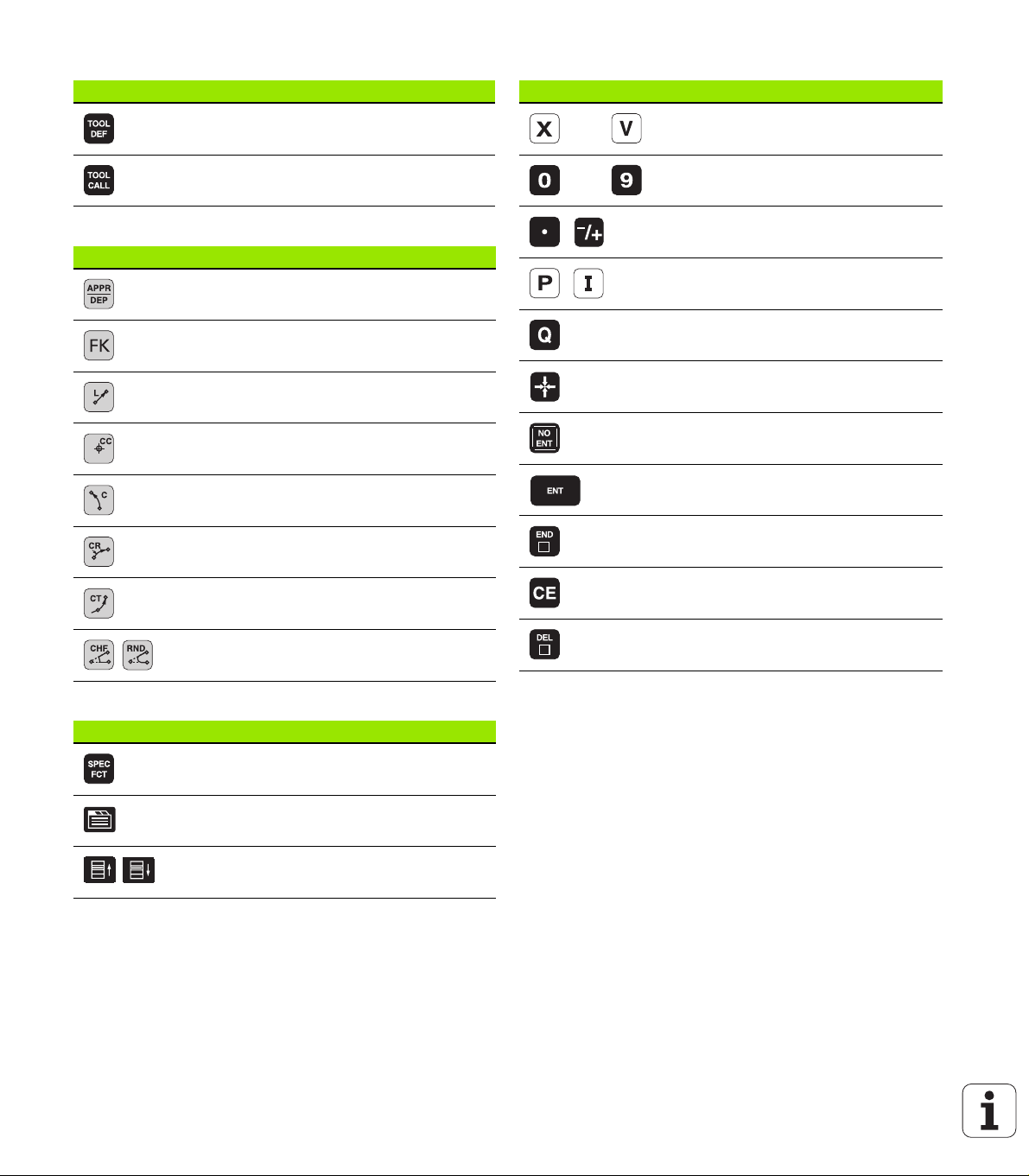
Tool functions
Key Function
Define tool data in the program
Coordinate axes and numbers: Entering and editing
Key Function
Select coordinate axes or
enter them into the program
Call tool data
Programming path movements
Key Function
Approach/depart contour
FK free contour programming
Straight line
Circle center/pole for polar coordinates
Circle with center
Circle with radius
Circular arc with tangential connection
Chamfering/corner rounding
Numbers
Decimal point / Reverse algebraic sign
Polar coordinate input / Incremental
values
Q-parameter programming /
Q-parameter status
Save actual position or values from
calculator
Skip dialog questions, delete words
Confirm entry and resume dialog
Conclude block and exit entry
Clear numerical entry or TNC error
message
Abort dialog, delete program section
Special functions / smarT.NC
Key Function
Show special functions
smarT.NC: Select next tab on form
smarT.NC: Select first input field in
previous/next frame

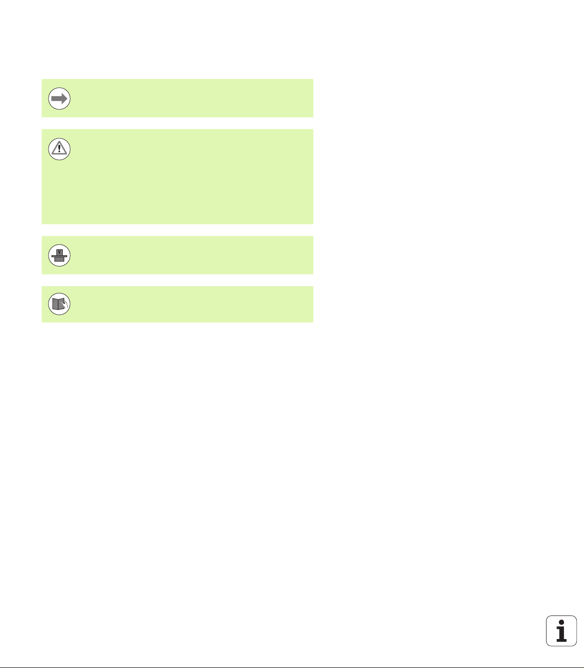
About this Manual
The symbols used in this manual are described below.
This symbol indicates that important information about the
function described must be considered.
This symbol indicates that there is one or more of the
following risks when using the described function:
Danger to workpiece
Danger to fixtures
Danger to tool
Danger to machine
Danger to operator
This symbol indicates that the described function must be
adapted by the machine tool builder. The function
described may therefore vary depending on the machine.
This symbol indicates that you can find detailed
information about a function in another manual.
About this Manual
Would you like any changes, or have you found any errors?
We are continuously striving to improve documentation for you.
Please help us by sending your requests to the following e-mail
address: tnc-userdoc@heidenhain.de.
HEIDENHAIN iTNC 530 5

TNC Model, Software and Features
This manual describes functions and features provided by TNCs as of
the following NC software numbers.
TNC model NC software number
iTNC 530, HSCI and HeROS 5 606 420-02
iTNC 530, HSCI and HeROS 5 606 421-02
iTNC 530 Programming
Workstation, HeROS 5
The suffix E indicates the export version of the TNC. The export
versions of the TNC have the following limitations:
Simultaneous linear movement in up to 4 axes
HSCI (HEIDENHAIN Serial Controller Interface) identifies the new
hardware platform of the TNC controls.
HeROS 5 identifies the operating system of HSCI-based TNC controls.
The machine tool builder adapts the usable features of the TNC to his
machine by setting machine parameters. Some of the functions
described in this manual may therefore not be among the features
provided by the TNC on your machine tool.
TNC Model, Software and Features
TNC functions that may not be available on your machine include:
Tool measurement with the TT
Please contact your machine tool builder to become familiar with the
features of your machine.
606 421-02
6

Many machine manufacturers, as well as HEIDENHAIN, offer
programming courses for the TNCs. We recommend these courses as
an effective way of improving your programming skill and sharing
information and ideas with other TNC users.
User’s Manual for Cycle Programming:
All of the cycle functions (touch probe cycles and fixed
cycles) are described in a separate manual. Please contact
HEIDENHAIN if you require a copy of this User’s Manual.
ID: 670 388-xx
smarT.NC user documentation:
The smarT.NC operating mode is described in a separate
Pilot. Please contact HEIDENHAIN if you require a copy of
this Pilot. ID: 533 191-xx.
TNC Model, Software and Features
HEIDENHAIN iTNC 530 7

Software options
The iTNC 530 features various software options that can be enabled
by you or your machine tool builder. Each option is to be enabled
separately and contains the following respective functions:
Software option 1
Cylinder surface interpolation (Cycles 27, 28, 29 and 39)
Feed rate in mm/min for rotary axes: M116
Tilting the machining plane (Cycle 19, PLANE function and 3-D ROT
soft key in the Manual operating mode)
Circle in 3 axes with tilted working plane
Software option 2
5-axis interpolation
Spline interpolation
3-D machining:
M114: Automatic compensation of machine geometry when
working with swivel axes
TNC Model, Software and Features
M128: Maintaining the position of the tool tip when positioning
with tilted axes (TCPM)
FUNCTION TCPM: Maintaining the position of the tool tip when
positioning with tilted axes (TCPM) in selectable modes
M144: Compensating the machine’s kinematic configuration for
ACTUAL/NOMINAL positions at end of block
Additional parameters for finishing/roughing and tolerance
for rotary axes in Cycle 32 (G62)
LN blocks (3-D compensation)
DCM Collision software option Description
Function that monitors areas defined by the
machine manufacturer to prevent collisions.
DXF Converter software option Description
Extract contours and machining positions
from DXF files (R12 format).
Additional dialog language software
option
Function for enabling the conversational
languages Slovenian, Slovak, Norwegian,
Latvian, Estonian, Korean, Turkish, Romanian,
Lithuanian.
8
Page 396
Page 268
Description
Page 680

Global Program Settings software option Description
Function for superimposing coordinate
transformations in the Program Run modes,
handwheel superimposed traverse in virtual
axis direction.
AFC software option Description
Function for adaptive feed-rate control for
optimizing the machining conditions during
series production.
KinematicsOpt software option Description
Touch-probe cycles for inspecting and
optimizing the machine accuracy.
3D-ToolComp software option Description
3-D radius compensation depending on the
tool’s contact angle for LN blocks.
Page 416
Page 427
User’s Manual for
Cycles
Page 427
Extended Tool Management software
option
Tool management that can be changed by the
machine manufacturer using Python scripts.
Interpolation Turning software option Description
Interpolation turning of a shoulder with cycle
290.
CAD Viewer software option Description
Opening of 3-D models on the NC control. Page 285
Remote Desktop Manager software
option
Remote operation of external computer units
(e.g. a Windows PC) via the user interface of
the TNC
Description
Page 200
User’s Manual for
Cycles
Description
Page 712
TNC Model, Software and Features
HEIDENHAIN iTNC 530 9

Cross Talk Compensation software option
(CTC)
Compensation of axis couplings Machine Manual
Description
Position Adaptive Control (PAC) software
option
Changing control parameters Machine Manual
Load Adaptive Control (LAC) software
option
Dynamic changing of control parameters Machine Manual
Description
Description
TNC Model, Software and Features
10

Feature content level (upgrade functions)
Along with software options, significant further improvements of the
TNC software are managed via the Feature Content Level (FCL)
upgrade functions. Functions subject to the FCL are not available
simply by updating the software on your TNC.
All upgrade functions are available to you without surcharge
when you receive a new machine.
Upgrade functions are identified in the manual with FCL n, where n
indicates the sequential number of the feature content level.
You can purchase a code number in order to permanently enable the
FCL functions. For more information, contact your machine tool
builder or HEIDENHAIN.
FCL 4 functions Description
Graphical depiction of the protected
space when DCM collision monitoring is
active
Page 400
Handwheel superimposition in stopped
condition when DCM collision
monitoring is active
3-D basic rotation (set-up
compensation)
FCL 3 functions Description
Touch probe cycle for 3-D probing User’s Manual for
Touch probe cycles for automatic datum
setting using the center of a slot/ridge
Feed-rate reduction for the machining of
contour pockets with the tool being in
full contact with the workpiece
PLANE function: Entry of axis angle Page 484
User documentation as a
context-sensitive help system
smarT.NC: Programming of smarT.NC
and machining can be carried out
simultaneously
Page 399
Machine Manual
Cycles
User’s Manual for
Cycles
User’s Manual for
Cycles
Page 164
Page 124
TNC Model, Software and Features
HEIDENHAIN iTNC 530 11

FCL 3 functions Description
smarT.NC: Contour pocket on point
pattern
smarT.NC Pilot
smarT.NC: Preview of contour
programs in the file manager
smarT.NC: Positioning strategy for
machining point patterns
FCL 2 functions Description
3-D line graphics Page 156
Virtual tool axis Page 601
USB support of block devices (memory
sticks, hard disks, CD-ROM drives)
Filtering of externally created contours Page 441
Possibility of assigning different depths
to each subcontour in the contour
formula
Touch-probe cycle for global setting of
TNC Model, Software and Features
touch-probe parameters
smarT.NC: Graphic support of block
scan
smarT.NC: Coordinate transformation smarT.NC Pilot
smarT.NC: PLANE function smarT.NC Pilot
smarT.NC Pilot
smarT.NC Pilot
Page 134
User’s Manual for
Cycles
User’s Manual for
Touch Probe Cycles
smarT.NC Pilot
Intended place of operation
The TNC complies with the limits for a Class A device in accordance
with the specifications in EN 55022, and is intended for use primarily
in industrially-zoned areas.
Legal information
This product uses open source software. Further information is
available on the control under
U Programming and Editing operating mode
U MOD function
U LEGAL INFORMATION soft key
12

New functions 606 42x-01 since the predecessor versions 340 49x-05
Opening and Editing of externally created files is new (see
“Additional tools for management of external file types” on page
139)
New functions in the task bar added (see “Soft-key row” on page
92)
Enhanced functions for configuration of the Ethernet interface (see
“Configuring the TNC” on page 651)
Improvements regarding Functional Safety FS (option):
General information on Functional Safety FS (see “General
Information” on page 560)
Explanation of terms (see “Explanation of terms” on page 561)
Checking the axis positions (see “Check axis positions” on page
562)
Activating feed-rate limitation (see “Activating feed-rate
limitation” on page 564)
Improvements regarding the general status view of a TNC with
functional safety (see “Additional Status displays” on page 564)
The new HR 520 and HR 550 FS handwheels are supported (see
“Traversing with electronic handwheels” on page 548)
New software option 3-D ToolComp: 3-D tool radius compensation
depending on the tool’s contact angle on blocks with surface normal
vectors (LN blocks, see "3-D tool radius compensation depending on
the tool’s contact angle (3D-ToolComp software option)", page 515)
3-D line graphics is now also possible in full-screen mode (see “3-D
Line Graphics (FCL2 Function)” on page 156)
A file selection dialog for selecting files in different NC functions and
in the table view of the pallet table is available now (see “Calling any
program as a subprogram” on page 291)
DCM: Saving and restoring of fixture situations
DCM: The form for test program generation now also contains icons
and tooltips (see “Check the position of the measured fixture” on
page 408)
DCM, FixtureWizard: Touch points and probing sequence are shown
more clearly now
DCM, FixtureWizard: Designations, touch points and measuring
points can be shown or hidden as desired.(see “Operating
FixtureWizard” on page 405)
DCM, FixtureWizard: Chucking equipment and insertion points can
now also be selected by mouse click
DCM: A library with standard chucking equipment is available now
(see “Fixture templates” on page 404)
DCM: Tool carrier management (see “Tool Holder Management
(DCM Software Option)” on page 413)
In the Test Run mode, the working plane can now by defined
manually (see “Setting a tilted working plane for the test run” on
page 626)
New functions 606 42x-01 since the predecessor versions 340 49x-05
HEIDENHAIN iTNC 530 13

In Manual mode the RW-3D mode for position display is now also
available (see “Position Display Types” on page 663)
Entries in the tool table TOOL.T (see “Tool table: Standard tool data”
on page 176)
New DR2TABLE column for definition of a compensation table for
tool radius compensation depending on the tool’s contact angle
New LAST_USE column, into which the TNC enters the date and
time of the last tool call
Q parameter programming: QS string parameters can now also be
used for jump addresses of conditional jumps, subprograms or
program section repeats (see "Calling a subprogram", page 289, see
"Calling a program section repeat", page 290 and see "Programming
If-Then decisions", page 315)
The generation of tool usage lists in the Program Run modes can be
configured in a form (see “Settings for the tool usage test” on page
197)
The behavior during deletion of tools from the tool table can now be
influenced via machine parameter 7263 see "Editing tool tables",
page 183
In the positioning mode TURN of the PLANE function you can now
define a clearance height to which the tool is to be retracted before
tilting to tool axis direction (see “Automatic positioning:
MOVE/TURN/STAY (entry is mandatory)” on page 486)
The following additional functions are now available in the expanded
tool management (see “Tool management (software option)” on
page 200):
Columns with special functions are also editable now
The form view of the tool data can now be exited with or without
saving changed values
The table view now offers a search function
Indexed tools are now shown correctly in the form view
The tool sequence list includes more detailed information now
The loading and unloading list of the tool magazine can now be
loaded and unloaded by drag and drop
Columns in the table view can be moved simply by drag and drop
Several special functions (SPEC FCT) are now available in the MDI
operating mode (see “Programming and Executing Simple
Machining Operations” on page 604)
There is a new manual probing cycle that can be used to
compensate workpiece misalignments by rotating the rotary table
(see “Workpiece alignment using 2 points” on page 586)
New touch probe cycle for calibrating a touch probe by means of a
calibration sphere (see User's Manual for Cycle Programming)
New functions 606 42x-01 since the predecessor versions 340 49x-05
14

KinematicsOpt: Better support for positioning of Hirth-coupled axes
(see User's Manual for Cycle Programming)
KinematicsOpt: An additional parameter for determination of the
backlash in a rotary axis was introduced (see User's Manual for
Cycle Programming)
New Cycle 275 for Trochoidal Slot Milling (see User’s Manual for
Cycle Programming)
In Cycle 241 "Single-Fluted Deep-Hole Drilling" it is now possible to
define a dwell depth (see User's Manual for Cycle Programming)
The approach and departure behavior of Cycle 39 "Cylinder Surface
Contour" can now be adjusted (see User's Manual for Cycle
Programming)
HEIDENHAIN iTNC 530 15
New functions 606 42x-01 since the predecessor versions 340 49x-05

New Functions with 606 42x-02
New function for opening 3-D data (software option) directly on the
TNC (see "Open 3-D CAD data (software option)" page 285)
Improvement of Dynamic Collision Monitoring (DCM):
Chucking equipment archives can now be activated (see “Loading
fixtures under program control” on page 412) and deactivated
(see “Deactivating fixtures under program control” on page 412)
under program control
The display of stepped tools has been improved
When you select tool carrier kinematics, the TNC now displays a
graphical preview of the carrier kinematics (see “Assigning the
tool-carrier kinematics” on page 186)
Extension of the functions for multiple axis machining:
In manual mode, you can now also travel the axes again when
TCPM and Tilt Machining Plane are active at the same time
You can now also change tools when M128/FUNCTION TCPM is active
File management: archiving of files in ZIP archives (see "Archive
files" page 137)
The nesting depth for program calls has been increased from 6 to 10
New Functions with 606 42x-02
(see “Nesting depth” on page 293)
smarT.NC-UNITs can now be inserted anywhere in plain-language
programs (see “smartWizard” on page 447)
There is now a search function based on tool names available in the
tool selection pop-up window (see “Search for tool names in the
selection window” on page 193)
Improvements in pallet machining:
The new column FIXTURE has been added to the pallet table to be
able to activate fixtures automatically (see "Pallet Operation with
Tool-Oriented Machining" page 528)
The new workpiece status SKIP has been added to the pallet table
(see "Setting up the pallet level" page 534)
If a tool sequence list is created for a pallet table, the TNC now
also checks that all the NC programs of the pallet table are
available (see “Calling tool management” on page 200)
The new host computer operation was introduced (see “Host
computer operation” on page 675)
The SELinux security software is available (see “SELinux security
software” on page 93)
16

Improvements to the DXF converter:
Contours can now also be extracted from .H files (see “Data
transfer from plain-language programs” on page 284)
Preselected contours can now also be selected in the tree
structure (see “Selecting and saving a contour” on page 274)
A snap function facilitates contour selection
Extended status display (see “Basic settings” on page 270)
Adjustable background color (see “Basic settings” on page 270)
Display can be changed between 2-D and 3-D (see “Basic
settings” on page 270)
Improvements to the global program settings (GS):
All the form data can now be set and reset under program control
(see “Technical prerequisites” on page 418)
Handwheel superimposition value VT can be reset when tool is
changed (see “Virtual axis VT” on page 426)
If the Swapping Axes function is active, it is now permitted to
position to machine-based positions on the axes that have not
been swapped
Using the new SEL PGM function you can assign variable program
names via QS string parameters call them with CALL SELECTED (see
“Define program call” on page 446)
Improvements to the tool table TOOL.T
Using the FIND ACTIVE TOOL NAMES soft key you can check
whether identical tool names are defined in the tool table (see
"Editing tool tables" page 183)
The input range of the delta values DL, DR and DR2 have been
increased to 999.9999 mm (see "Tool table: Standard tool data"
page 176)
The following additional functions are now available in the expanded
tool management (see “Tool management (software option)” on
page 200):
Importing of tool data in CSV format (see “Import tool data” on
page 205)
Exporting of tool data in CSV format (see “Export the tool data”
on page 206)
Marking and deleting of selectable tool data (see “Delete marked
tool data” on page 207)
Inserting of tool indices (see “Operating the tool management”
on page 202)
New Functions with 606 42x-02
HEIDENHAIN iTNC 530 17

New cycle 225 Engraving (see User’s Manual for Cycle
Programming)
New cycle 276 Contour Train (see User’s Manual for Cycle
Programming)
New cycle 290 Interpolation Turning (software option, see User’s
Manual for Cycle Programming)
In the thread milling cycles 26x a separate feed rate is now available
for tangential approach to the thread (see User’s Manual for Cycle
Programming)
The following improvements were made to the KinematicsOpt
cycles (see User’s Manual for Conversational Programming):
Newer, faster optimization algorithm
It is no longer necessary to run a separate measurement series for
position optimization after angle optimization
Return of the offset errors (change of machine datum) to the
parameters Q147-149
More plane measuring points for ball measurement
Rotary axes that are not configured are ignored by TNC when
executing the cycle
New Functions with 606 42x-02
18

Changed functions 606 42x-01 since the predecessor versions 340 49x-06
Q-parameter programming: In the FN20 function WAIT FOR you can
now enter 128 characters (see “FN 20: WAIT FOR: NC and PLC
synchronization” on page 335)
In the calibration menus for touch probe length and radius, the
number and name of the active tool are also displayed now (if the
calibration data from the tool table are to be used, MP7411 = 1, see
"Managing more than one block of calibrating data", page 580)
During tilting in the Distance-To-Go mode, the PLANE function now
shows the angle actually left to be traversed until the target position
(see “Position display” on page 471)
The approach behavior during side finishing with Cycle 24 (DIN/ISO:
G124) was changed (see User's Manual for Cycle Programming).
HEIDENHAIN iTNC 530 19
Changed functions 606 42x-01 since the predecessor versions 340 49x-06

Changed functions with 606 42x-02
Tool names can now be defined with 32 characters (see “Tool
numbers and tool names” on page 174)
Improved and simplified operation by mouse and touchpad in all
graphics windows (see “Functions of the 3-D line graphics” on page
156)
Various pop-up windows have been redesigned
If you do a Test Run without calculating the machining time, the TNC
generates a tool usage file nevertheless (see “Tool usage test” on
page 197)
The size of the Service ZIP files has been increased to 40 MB (see
“Generating service files” on page 163)
M124 can now be deactivated by entering M124 without T (see “Do
not include points when executing non-compensated line blocks:
M124” on page 374)
The PRESET TABLE soft key has been renamed to DATUM
MANAGEMENT
The SAVE PRESET soft key has been renamed to SAVE ACTIVE
PRESET
Changed functions with 606 42x-02
20

Table of Contents
First Steps with the iTNC 530
1
Introduction
2
Programming: Fundamentals,
File Management
3
Programming: Programming Aids
4
Programming: Tools
5
Programming: Programming Contours
6
Programming: Data Transfer from DXF Files
or Plain-language Contours
7
Programming: Subprograms and Program
Section Repeats
8
Programming: Q-Parameters
9
Programming: Miscellaneous Functions
10
Programming: Special Functions
11
Programming: Multiple Axis Machining
12
Programming: Pallet Editor
13
Manual Operation and Setup
14
Positioning with Manual Data Input
15
Test Run and Program Run
16
MOD Functions
17
Tables and Overviews
18
Industrial PC 6341 with Windows 7 (Option)
19
HEIDENHAIN iTNC 530 21


1 First Steps with the iTNC 530 ..... 51
1.1 Overview ..... 52
1.2 Machine Switch-On ..... 53
Acknowledge the power interruption and move to the reference points ..... 53
1.3 Programming the First Part ..... 54
Select the correct operating mode ..... 54
The most important TNC keys ..... 54
Create a new program/file management ..... 55
Define a workpiece blank ..... 56
Program layout ..... 57
Program a simple contour ..... 58
Create a cycle program ..... 61
1.4 Graphically Testing the First Program ..... 64
Selecting the correct operating mode ..... 64
Select the tool table for the test run ..... 64
Choose the program you want to test ..... 65
Select the screen layout and the view ..... 65
Start the program test ..... 65
1.5 Tool Setup ..... 66
Selecting the correct operating mode ..... 66
Prepare and measure tools ..... 66
The tool table TOOL.T ..... 66
The pocket table TOOL_P.TCH ..... 67
1.6 Workpiece Setup ..... 68
Selecting the correct operating mode ..... 68
Clamp the workpiece ..... 68
Align the workpiece with a 3-D touch probe system ..... 69
Set the datum with a 3-D touch probe ..... 70
1.7 Running the First Program ..... 71
Selecting the correct operating mode ..... 71
Choose the program you want to run ..... 71
Start the program ..... 71
HEIDENHAIN iTNC 530 23

2 Introduction ..... 73
2.1 The iTNC 530 ..... 74
Programming: HEIDENHAIN conversational, smarT.NC and ISO formats ..... 74
Compatibility ..... 74
2.2 Visual Display Unit and Keyboard ..... 75
Visual display unit ..... 75
Sets the screen layout ..... 76
Operating panel ..... 77
2.3 Operating Modes ..... 78
Manual Operation and Electronic Handwheel ..... 78
Positioning with Manual Data Input ..... 78
Programming and Editing ..... 79
Test Run ..... 79
Program Run, Full Sequence and Program Run, Single Block ..... 80
2.4 Status Displays ..... 81
“General” status display ..... 81
Additional status displays ..... 83
2.5 Window Manager ..... 91
Soft-key row ..... 92
2.6 SELinux security software ..... 93
2.7 Accessories: HEIDENHAIN 3-D Touch Probes and Electronic Handwheels ..... 94
3-D touch probes ..... 94
HR electronic handwheels ..... 95
24

3 Programming: Fundamentals, File Management ..... 97
3.1 Fundamentals ..... 98
Position encoders and reference marks ..... 98
Reference system ..... 98
Reference system on milling machines ..... 99
Polar coordinates ..... 100
Absolute and incremental workpiece positions ..... 101
Setting the datum ..... 102
3.2 Creating and Writing Programs ..... 103
Organization of an NC program in HEIDENHAIN Conversational ..... 103
Define the blank: BLK FORM ..... 103
Creating a new part program ..... 104
Programming tool movements in conversational format ..... 106
Actual position capture ..... 108
Editing a program ..... 109
The TNC search function ..... 113
3.3 File Management: Fundamentals ..... 115
Files ..... 115
Show externally created files on the TNC ..... 117
Data backup ..... 117
HEIDENHAIN iTNC 530 25

3.4 Working with the File Manager ..... 118
Directories ..... 118
Paths ..... 118
Overview: Functions of the file manager ..... 119
Calling the file manager ..... 121
Selecting drives, directories and files ..... 122
Creating a new directory (only possible on the drive TNC:\) ..... 125
Creating a new file (only possible on the drive TNC:\) ..... 125
Copying a single file ..... 126
Copying files into another directory ..... 127
Copying a table ..... 128
Copying a directory ..... 129
Choosing one of the last files selected ..... 129
Deleting a file ..... 130
Deleting a directory ..... 130
Marking files ..... 131
Renaming a file ..... 133
Additional functions ..... 134
Working with shortcuts ..... 136
Archive files ..... 137
Extract files from archive ..... 138
Additional tools for management of external file types ..... 139
Data transfer to or from an external data medium ..... 144
The TNC in a network ..... 146
USB devices on the TNC (FCL 2 function) ..... 147
26

4 Programming: Programming Aids ..... 149
4.1 Adding Comments ..... 150
Function ..... 150
Entering comments during programming ..... 150
Inserting comments after program entry ..... 150
Entering a comment in a separate block ..... 150
Functions for editing of the comment ..... 151
4.2 Structuring Programs ..... 152
Definition and applications ..... 152
Displaying the program structure window / Changing the active window ..... 152
Inserting a structuring block in the (left) program window ..... 152
Selecting blocks in the program structure window ..... 152
4.3 Integrated Pocket Calculator ..... 153
Operation ..... 153
4.4 Programming Graphics ..... 154
Generating / not generating graphics during programming ..... 154
Generating a graphic for an existing program ..... 154
Block number display ON/OFF ..... 155
Erasing the graphic ..... 155
Magnifying or reducing a detail ..... 155
4.5 3-D Line Graphics (FCL2 Function) ..... 156
Function ..... 156
Functions of the 3-D line graphics ..... 156
Highlighting NC blocks in the graphics ..... 158
Block number display ON/OFF ..... 158
Erasing the graphic ..... 158
4.6 Immediate Help for NC Error Messages ..... 159
Displaying error messages ..... 159
Display HELP ..... 159
4.7 List of All Current Error Messages ..... 160
Function ..... 160
Show error list ..... 160
Window contents ..... 161
Calling the TNCguide help system ..... 162
Generating service files ..... 163
4.8 The Context-Sensitive Help System TNCguide (FCL3 Function) ..... 164
Function ..... 164
Working with the TNCguide ..... 165
Downloading current help files ..... 169
HEIDENHAIN iTNC 530 27

5 Programming: Tools ..... 171
5.1 Entering Tool-Related Data ..... 172
Feed rate F ..... 172
Spindle speed S ..... 173
5.2 Tool Data ..... 174
Requirements for tool compensation ..... 174
Tool numbers and tool names ..... 174
Tool length L ..... 174
Tool radius R ..... 174
Delta values for lengths and radii ..... 175
Entering tool data into the program ..... 175
Entering tool data in the table ..... 176
Tool-carrier kinematics ..... 186
Using an external PC to overwrite individual tool data ..... 187
Pocket table for tool changer ..... 188
Calling tool data ..... 191
Tool change ..... 194
Tool usage test ..... 197
Tool management (software option) ..... 200
5.3 Tool Compensation ..... 208
Introduction ..... 208
Tool length compensation ..... 208
Tool radius compensation ..... 209
28

6 Programming: Programming Contours ..... 213
6.1 Tool Movements ..... 214
Path functions ..... 214
FK free contour programming ..... 214
Miscellaneous functions M ..... 214
Subprograms and program section repeats ..... 214
Programming with Q parameters ..... 214
6.2 Fundamentals of Path Functions ..... 215
Programming tool movements for workpiece machining ..... 215
6.3 Contour Approach and Departure ..... 219
Overview: Types of paths for contour approach and departure ..... 219
Important positions for approach and departure ..... 220
Approaching on a straight line with tangential connection: APPR LT ..... 222
Approaching on a straight line perpendicular to the first contour point: APPR LN ..... 222
Approaching on a circular path with tangential connection: APPR CT ..... 223
Approaching on a circular arc with tangential connection from a straight line to the contour: APPR LCT ..... 224
Departing on a straight line with tangential connection: DEP LT ..... 225
Departing on a straight line perpendicular to the last contour point: DEP LN ..... 225
Departure on a circular path with tangential connection: DEP CT ..... 226
Departing on a circular arc tangentially connecting the contour and a straight line: DEP LCT ..... 226
6.4 Path Contours—Cartesian Coordinates ..... 227
Overview of path functions ..... 227
Straight line L ..... 228
Inserting a chamfer between two straight lines ..... 229
Corner rounding RND ..... 230
Circle center CCI ..... 231
Circular path C around circle center CC ..... 232
Circular path CR with defined radius ..... 233
Circular path CT with tangential connection ..... 235
6.5 Path Contours—Polar Coordinates ..... 240
Overview ..... 240
Zero point for polar coordinates: pole CC ..... 241
Straight line LP ..... 241
Circular path CP around pole CC ..... 242
Circular path CTP with tangential connection ..... 243
Helical interpolation ..... 244
HEIDENHAIN iTNC 530 29

6.6 Path Contours—FK Free Contour Programming ..... 248
Fundamentals ..... 248
Graphics during FK programming ..... 250
Converting FK programs into HEIDENHAIN conversational format ..... 251
Initiating the FK dialog ..... 251
Pole for FK programming ..... 253
Free programming of straight lines ..... 253
Free programming of circular arcs ..... 254
Input possibilities ..... 254
Auxiliary points ..... 258
Relative data ..... 259
30

7 Programming: Data Transfer from DXF Files or Plain-language Contours ..... 267
7.1 Processing DXF Files (Software Option) ..... 268
Function ..... 268
Opening a DXF file ..... 269
Basic settings ..... 270
Layer settings ..... 271
Specifying the reference point ..... 272
Selecting and saving a contour ..... 274
Selecting and storing machining positions ..... 277
Zoom function ..... 283
7.2 Data transfer from plain-language programs ..... 284
Application ..... 284
Open plain-language file ..... 284
Define a reference point; select and save contours ..... 284
7.3 Open 3-D CAD data (software option) ..... 285
Application ..... 285
Operate CAD viewer ..... 286
HEIDENHAIN iTNC 530 31

8 Programming: Subprograms and Program Section Repeats ..... 287
8.1 Labeling Subprograms and Program Section Repeats ..... 288
Labels ..... 288
8.2 Subprograms ..... 289
Operating sequence ..... 289
Programming notes ..... 289
Programming a subprogram ..... 289
Calling a subprogram ..... 289
8.3 Program Section Repeats ..... 290
Label LBL ..... 290
Operating sequence ..... 290
Programming notes ..... 290
Programming a program section repeat ..... 290
Calling a program section repeat ..... 290
8.4 Separate Program as Subprogram ..... 291
Operating sequence ..... 291
Programming notes ..... 291
Calling any program as a subprogram ..... 291
8.5 Nesting ..... 293
Types of nesting ..... 293
Nesting depth ..... 293
Subprogram within a subprogram ..... 294
Repeating program section repeats ..... 295
Repeating a subprogram ..... 296
8.6 Programming Examples ..... 297
32

9 Programming: Q-Parameters ..... 303
9.1 Principle and Overview ..... 304
Programming notes ..... 306
Calling Q-parameter functions ..... 307
9.2 Part Families—Q Parameters in Place of Numerical Values ..... 308
Function ..... 308
9.3 Describing Contours through Mathematical Operations ..... 309
Function ..... 309
Overview ..... 309
Programming fundamental operations ..... 310
9.4 Trigonometric Functions ..... 311
Definitions ..... 311
Programming trigonometric functions ..... 312
9.5 Circle Calculations ..... 313
Function ..... 313
9.6 If-Then Decisions with Q Parameters ..... 314
Function ..... 314
Unconditional jumps ..... 314
Programming If-Then decisions ..... 315
Abbreviations used: ..... 315
9.7 Checking and Changing Q Parameters ..... 316
Procedure ..... 316
9.8 Additional Functions ..... 317
Overview ..... 317
FN 14: ERROR: Displaying error messages ..... 318
FN 15: PRINT: Output of texts or Q parameter values ..... 322
FN 16: F-PRINT: Formatted output of text and Q-parameter values ..... 323
FN 18: SYS-DATUM READ: Read system data ..... 327
FN 19: PLC: Transfer values to the PLC ..... 334
FN 20: WAIT FOR: NC and PLC synchronization ..... 335
FN 25: PRESET: Setting a new datum ..... 337
9.9 Entering Formulas Directly ..... 338
Entering formulas ..... 338
Rules for formulas ..... 340
Programming example ..... 341
HEIDENHAIN iTNC 530 33

9.10 String Parameters ..... 342
String processing functions ..... 342
Assigning string parameters ..... 343
Chain-linking string parameters ..... 344
Converting a numerical value to a string parameter ..... 345
Copying a substring from a string parameter ..... 346
Copying system data to a string parameter ..... 347
Converting a string parameter to a numerical value ..... 349
Checking a string parameter ..... 350
Finding the length of a string parameter ..... 351
Comparing alphabetic priority ..... 352
9.11 Preassigned Q Parameters ..... 353
Values from the PLC: Q100 to Q107 ..... 353
WMAT block: QS100 ..... 353
Active tool radius: Q108 ..... 353
Tool axis: Q109 ..... 354
Spindle status: Q110 ..... 354
Coolant on/off: Q111 ..... 354
Overlap factor: Q112 ..... 354
Unit of measurement for dimensions in the program: Q113 ..... 355
Tool length: Q114 ..... 355
Coordinates after probing during program run ..... 355
Deviation between actual value and nominal value during automatic tool measurement with the TT 130 ..... 356
Tilting the working plane with mathematical angles: rotary axis coordinates calculated by the TNC ..... 356
Measurement results from touch probe cycles (see also User’s Manual for Touch Probe Cycles) ..... 357
9.12 Programming Examples ..... 359
34

10 Programming: Miscellaneous Functions ..... 367
10.1 Entering Miscellaneous Functions M and STOP ..... 368
Fundamentals ..... 368
10.2 Miscellaneous Functions for Program Run Control, Spindle and Coolant ..... 369
Overview ..... 369
10.3 Miscellaneous Functions for Coordinate Data ..... 370
Programming machine-referenced coordinates: M91/M92 ..... 370
Activating the most recently entered datum: M104 ..... 372
Moving to positions in a non-tilted coordinate system with a tilted working plane: M130 ..... 372
10.4 Miscellaneous Functions for Contouring Behavior ..... 373
Smoothing corners: M90 ..... 373
Insert rounding arc between straight lines: M112 ..... 373
Do not include points when executing non-compensated line blocks: M124 ..... 374
Machining small contour steps: M97 ..... 375
Machining open contours corners: M98 ..... 377
Feed rate factor for plunging movements: M103 ..... 378
Feed rate in millimeters per spindle revolution: M136 ..... 379
Feed rate for circular arcs: M109/M110/M111 ..... 380
Calculating the radius-compensated path in advance (LOOK AHEAD): M120 ..... 381
Superimposing handwheel positioning during program run: M118 ..... 383
Retraction from the contour in the tool-axis direction: M140 ..... 384
Suppressing touch probe monitoring: M141 ..... 385
Delete modal program information: M142 ..... 386
Delete basic rotation: M143 ..... 386
Automatically retract tool from the contour at an NC stop: M148 ..... 387
Suppress limit switch message: M150 ..... 388
10.5 Miscellaneous Functions for Laser Cutting Machines ..... 389
Principle ..... 389
Output the programmed voltage directly: M200 ..... 389
Output voltage as a function of distance: M201 ..... 389
Output voltage as a function of speed: M202 ..... 390
Output voltage as a function of time (time-dependent ramp): M203 ..... 390
Output voltage as a function of time (time-dependent pulse): M204 ..... 390
HEIDENHAIN iTNC 530 35

11 Programming: Special Functions ..... 391
11.1 Overview of Special Functions ..... 392
Main menu for SPEC FCT special functions ..... 392
Program defaults menu ..... 393
Functions for contour and point machining menu ..... 393
Functions for contour and point machining menu ..... 394
Menu of various conversational functions ..... 394
Menu of programming aids ..... 395
11.2 Dynamic Collision Monitoring (Software Option) ..... 396
Function ..... 396
Collision monitoring in the manual operating modes ..... 398
Collision monitoring in Automatic operation ..... 399
Graphic depiction of the protected space (FCL4 function) ..... 400
Collision monitoring in the Test Run mode of operation ..... 401
11.3 Fixture Monitoring (DCM Software Option) ..... 403
Fundamentals ..... 403
Fixture templates ..... 404
Setting parameter values for the fixture: FixtureWizard ..... 404
Placing the fixture on the machine ..... 406
Editing fixtures ..... 407
Removing fixtures ..... 407
Check the position of the measured fixture ..... 408
Manage fixtures ..... 410
11.4 Tool Holder Management (DCM Software Option) ..... 413
Fundamentals ..... 413
Tool-holder templates ..... 413
Set the tool holder parameters: ToolHolderWizard ..... 414
Removing a tool holder ..... 415
11.5 Global Program Settings (Software Option) ..... 416
Application ..... 416
Technical prerequisites ..... 418
Activating/deactivating a function ..... 419
Basic rotation ..... 421
Swapping axes ..... 422
Superimposed mirroring ..... 423
Additional, additive datum shift ..... 423
Axis locking ..... 424
Superimposed rotation ..... 424
Feed rate override ..... 424
Handwheel superimposition ..... 425
36

11.6 Adaptive Feed Control Software Option (AFC) ..... 427
Application ..... 427
Defining the AFC basic settings ..... 429
Recording a teach-in cut ..... 431
Activating/deactivating AFC ..... 434
Log file ..... 435
Tool breakage/tool wear monitoring ..... 437
Spindle load monitoring ..... 437
11.7 Generate a Backward Program ..... 438
Function ..... 438
Prerequisites for the program to be converted ..... 439
Application example ..... 440
11.8 Filtering Contours (FCL 2 Function) ..... 441
Function ..... 441
11.9 File Functions ..... 442
Application ..... 442
Defining file functions ..... 442
11.10 Defining Coordinate Transformations ..... 443
Overview ..... 443
TRANS DATUM AXIS ..... 443
TRANS DATUM TABLE ..... 444
TRANS DATUM RESET ..... 445
Define program call ..... 446
11.11 smartWizard ..... 447
Application ..... 447
Insert UNIT ..... 448
Edit UNIT ..... 449
HEIDENHAIN iTNC 530 37

11.12 Creating Text Files ..... 450
Application ..... 450
Opening and exiting text files ..... 450
Editing texts ..... 451
Deleting and re-inserting characters, words and lines ..... 452
Editing text blocks ..... 453
Finding text sections ..... 454
11.13 Working with Cutting Data Tables ..... 455
Note ..... 455
Applications ..... 455
Table for workpiece materials ..... 456
Table for tool cutting materials ..... 457
Table for cutting data ..... 457
Data required for the tool table ..... 458
Working with automatic speed / feed rate calculation ..... 459
Data transfer from cutting data tables ..... 460
Configuration file TNC.SYS ..... 460
11.14 Freely Definable Tables ..... 461
Fundamentals ..... 461
Creating a freely definable table ..... 461
Editing the table format ..... 462
Switching between table and form view ..... 463
FN26: TABOPEN: Opening a freely definable table ..... 464
FN 27: TABWRITE: Writing to a freely definable table ..... 465
FN28: TABREAD: Reading a freely definable table ..... 466
38

12 Programming: Multiple Axis Machining ..... 467
12.1 Functions for Multiple Axis Machining ..... 468
12.2 The PLANE Function: Tilting the Working Plane (Software Option 1) ..... 469
Introduction ..... 469
Define the PLANE function ..... 471
Position display ..... 471
Reset the PLANE function ..... 472
Defining the machining plane with space angles: PLANE SPATIAL ..... 473
Defining the machining plane with projection angles: PROJECTED PLANE ..... 475
Defining the machining plane with Euler angles: EULER PLANE ..... 477
Defining the working plane with two vectors: VECTOR PLANE ..... 479
Defining the machining plane via three points: PLANE POINTS ..... 481
Defining the machining plane with a single, incremental spatial angle: PLANE RELATIVE ..... 483
Tilting the working plane through axis angle: PLANE AXIAL (FCL 3 function) ..... 484
Specifying the positioning behavior of the PLANE function ..... 486
12.3 Inclined-Tool Machining in the Tilted Plane ..... 491
Function ..... 491
Inclined-tool machining via incremental traverse of a rotary axis ..... 491
Inclined-tool machining via normal vectors ..... 492
12.4 TCPM FUNCTION (Software Option 2) ..... 493
Function ..... 493
Define TCPM FUNCTION ..... 494
Mode of action of the programmed feed rate ..... 494
Interpretation of the programmed rotary axis coordinates ..... 495
Type of interpolation between the starting and end position ..... 496
Reset TCPM FUNCTION ..... 497
12.5 Miscellaneous Functions for Rotary Axes ..... 498
Feed rate in mm/min on rotary axes A, B, C: M116 (software option 1) ..... 498
Shorter-path traverse of rotary axes: M126 ..... 499
Reducing display of a rotary axis to a value less than 360°: M94 ..... 500
Automatic compensation of machine geometry when working with tilted axes: M114 (software option 2) ..... 501
Maintaining the position of the tool tip when positioning with tilted axes (TCPM): M128 (software
option 2) ..... 503
Exact stop at corners with nontangential transitions: M134 ..... 506
Selecting tilting axes: M138 ..... 506
Compensating the machine’s kinematics configuration for ACTUAL/NOMINAL positions at end of block: M144
(software option 2) ..... 507
HEIDENHAIN iTNC 530 39

12.6 Three-Dimensional Tool Compensation (Software Option 2) ..... 508
Introduction ..... 508
Definition of a normalized vector ..... 509
Permissible tool forms ..... 510
Using other tools: Delta values ..... 510
3-D compensation without tool orientation ..... 511
Face milling: 3-D compensation with and without tool orientation ..... 511
Peripheral milling: 3-D radius compensation with workpiece orientation ..... 513
3-D tool radius compensation depending on the tool’s contact angle (3D-ToolComp software option) ..... 515
12.7 Contour Movements – Spline Interpolation (Software Option 2) ..... 519
Application ..... 519
40

13 Programming: Pallet Editor ..... 521
13.1 Pallet Editor ..... 522
Application ..... 522
Selecting a pallet table ..... 524
Leaving the pallet file ..... 524
Pallet datum management with the pallet preset table ..... 525
Executing the pallet file ..... 527
13.2 Pallet Operation with Tool-Oriented Machining ..... 528
Application ..... 528
Selecting a pallet file ..... 533
Setting up the pallet file with the entry form ..... 533
Sequence of tool-oriented machining ..... 538
Leaving the pallet file ..... 539
Executing the pallet file ..... 539
HEIDENHAIN iTNC 530 41

14 Manual Operation and Setup ..... 541
14.1 Switch-On, Switch-Off ..... 542
Switch-on ..... 542
Switch-off ..... 545
14.2 Moving the Machine Axes ..... 546
Note ..... 546
Moving the axis using the machine axis direction buttons ..... 546
Incremental jog positioning ..... 547
Traversing with electronic handwheels ..... 548
14.3 Spindle Speed S, Feed Rate F and Miscellaneous Functions M ..... 558
Function ..... 558
Entering values ..... 558
Changing the spindle speed and feed rate ..... 559
14.4 Functional Safety FS (Option) ..... 560
General Information ..... 560
Explanation of terms ..... 561
Check axis positions ..... 562
Overview of permitted feed rates and speeds ..... 563
Activating feed-rate limitation ..... 564
Additional Status displays ..... 564
14.5 Datum Setting without a 3-D Touch Probe ..... 565
Note ..... 565
Preparation ..... 565
Workpiece presetting with axis keys ..... 566
Datum management with the preset table ..... 567
14.6 Using the 3-D Touch Probe ..... 573
Overview ..... 573
Selecting probe cycles ..... 574
Recording measured values from the touch-probe cycles ..... 574
Writing the measured values from touch probe cycles in datum tables ..... 575
Writing the measured values from touch probe cycles in the preset table ..... 576
Storing measured values in the pallet preset table ..... 577
14.7 Calibrating a 3-D Touch Probe ..... 578
Introduction ..... 578
Calibrating the effective length ..... 578
Calibrating the effective radius and compensating center misalignment ..... 579
Displaying calibration values ..... 580
Managing more than one block of calibrating data ..... 580
14.8 Compensating Workpiece Misalignment with a 3-D Touch Probe ..... 581
Introduction ..... 581
Basic rotation using 2 points: ..... 583
Determining basic rotation using 2 holes/studs: ..... 585
Workpiece alignment using 2 points ..... 586
42

14.9 Datum Setting with a 3-D Touch Probe ..... 587
Overview ..... 587
Datum setting in any axis ..... 587
Corner as datum – using points that were already probed for a basic rotation ..... 588
Corner as datum—without using points that were already probed for a basic rotation. ..... 588
Circle center as datum ..... 589
Center line as datum ..... 590
Setting datum points using holes/cylindrical studs ..... 591
Measuring workpieces with a 3-D touch probe ..... 592
Using touch probe functions with mechanical probes or dial gauges ..... 595
14.10 Tilting the Working Plane (Software Option 1) ..... 596
Application, function ..... 596
Traversing the reference points in tilted axes ..... 598
Setting the datum in a tilted coordinate system ..... 598
Datum setting on machines with rotary tables ..... 599
Datum setting on machines with spindle-head changing systems ..... 599
Position display in a tilted system ..... 599
Limitations on working with the tilting function ..... 599
Activating manual tilting ..... 600
Setting the current tool-axis direction as the active machining direction (FCL 2 function) ..... 601
HEIDENHAIN iTNC 530 43

15 Positioning with Manual Data Input ..... 603
15.1 Programming and Executing Simple Machining Operations ..... 604
Positioning with Manual Data Input (MDI) ..... 604
Protecting and erasing programs in $MDI ..... 607
44

16 Test Run and Program Run ..... 609
16.1 Graphics ..... 610
Application ..... 610
Overview of display modes ..... 612
Plan view ..... 612
Projection in 3 planes ..... 613
3-D view ..... 614
Magnifying details ..... 617
Repeating graphic simulation ..... 618
Displaying the tool ..... 618
Measuring the machining time ..... 619
16.2 Functions for Program Display ..... 620
Overview ..... 620
16.3 Test Run ..... 621
Application ..... 621
16.4 Program Run ..... 627
Application ..... 627
Running a part program ..... 628
Interrupting machining ..... 629
Moving the machine axes during an interruption ..... 631
Resuming program run after an interruption ..... 632
Mid-program startup (block scan) ..... 633
Returning to the contour ..... 636
16.5 Automatic Program Start ..... 637
Application ..... 637
16.6 Optional Block Skip ..... 638
Application ..... 638
Erasing the “/” character ..... 638
16.7 Optional Program-Run Interruption ..... 639
Application ..... 639
HEIDENHAIN iTNC 530 45

17 MOD Functions ..... 641
17.1 Selecting MOD Functions ..... 642
Selecting the MOD functions ..... 642
Changing the settings ..... 642
Exiting the MOD functions ..... 642
Overview of MOD functions ..... 643
17.2 Software Numbers ..... 644
Application ..... 644
17.3 Entering Code Numbers ..... 645
Application ..... 645
17.4 Loading Service Packs ..... 646
Application ..... 646
17.5 Setting the Data Interfaces ..... 647
Application ..... 647
Setting the RS-232 interface ..... 647
Setting the RS-422 interface ..... 647
Setting the OPERATING MODE of the external device ..... 647
Setting the baud rate ..... 647
Assignment ..... 648
Software for data transfer ..... 649
17.6 Ethernet Interface ..... 651
Introduction ..... 651
Connection possibilities ..... 651
Configuring the TNC ..... 651
17.7 Configuring PGM MGT ..... 657
Application ..... 657
Changing the PGM MGT setting ..... 657
Dependent files ..... 658
17.8 Machine-Specific User Parameters ..... 659
Application ..... 659
17.9 Showing the Workpiece in the Working Space ..... 660
Application ..... 660
Rotate the entire image ..... 662
17.10 Position Display Types ..... 663
Application ..... 663
17.11 Unit of Measurement ..... 664
Application ..... 664
17.12 Selecting the Programming Language for $MDI ..... 665
Application ..... 665
17.13 Selecting the Axes for Generating L Blocks ..... 666
Application ..... 666
46

17.14 Entering the Axis Traverse Limits, Datum Display ..... 667
Application ..... 667
Working without additional traverse limits ..... 667
Find and enter the maximum traverse ..... 667
Datum display ..... 668
17.15 Displaying HELP Files ..... 669
Application ..... 669
Selecting HELP files ..... 669
17.16 Displaying Operating Times ..... 670
Application ..... 670
17.17 Checking the Data Carrier ..... 671
Application ..... 671
Performing the data carrier check ..... 671
17.18 Setting the System Time ..... 672
Application ..... 672
Selecting appropriate settings ..... 672
17.19 TeleService ..... 673
Application ..... 673
Calling/exiting TeleService ..... 673
17.20 External Access ..... 674
Application ..... 674
17.21 Host computer operation ..... 675
Application ..... 675
17.22 Configuring the HR 550 FS Wireless Handwheel ..... 676
Application ..... 676
Assigning the handwheel to a specific handwheel holder ..... 676
Setting the transmission channel ..... 677
Selecting the transmitter power ..... 678
Statistics ..... 678
HEIDENHAIN iTNC 530 47

18 Tables and Overviews ..... 679
18.1 General User Parameters ..... 680
Input possibilities for machine parameters ..... 680
Selecting general user parameters ..... 680
List of general user parameters ..... 681
18.2 Pin Layouts and Connecting Cables for the Data Interfaces ..... 696
RS-232-C/V.24 interface for HEIDENHAIN devices ..... 696
Non-HEIDENHAIN devices ..... 697
RS-422/V.11 interface ..... 698
Ethernet interface RJ45 socket ..... 699
18.3 Technical Information ..... 700
18.4 Exchanging the Buffer Battery ..... 710
48

19 Industrial PC 6341 with Windows 7 (Option) ..... 711
19.1 Introduction ..... 712
Functionality ..... 712
Specifications of the IPC 6341 ..... 712
End User License Agreement (EULA) for Windows 7 ..... 713
Switch to Windows interface ..... 713
Exiting Windows ..... 713
HEIDENHAIN iTNC 530 49

50
First Steps with the iTNC 530

1.1 Overview
This chapter is intended to help TNC beginners quickly learn to handle
the most important procedures. For more information on a respective
topic, see the section referred to in the text.
The following topics are included in this chapter
Machine Switch-On
1.1 Overview
Programming the First Part
Graphically Testing the Program
Tool Setup
Workpiece Setup
Running the First Program
52 First Steps with the iTNC 530
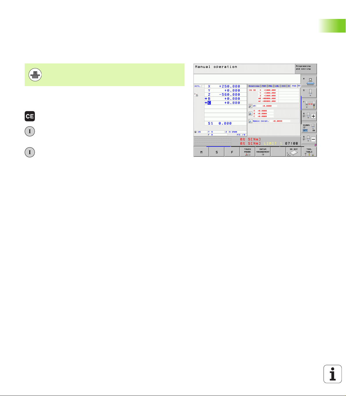
1.2 Machine Switch-On
Acknowledge the power interruption and move to the reference points
Switch-on and crossing the reference points can vary
depending on the machine tool. Your machine manual
provides more detailed information.
U Switch on the power supply for control and machine. The TNC starts
the operating system. This process may take several minutes. Then
the TNC will display the message “Power interruption.”
U Press the CE key: The TNC converts the PLC
program
U Switch on the control voltage: The TNC checks
operation of the emergency stop circuit and goes into
the reference run mode
U Cross the reference points manually in the displayed
sequence: For each axis press the machine START
button. If you have absolute linear and angle encoders
on your machine there is no need for a reference run
The TNC is now ready for operation in the Manual Operation mode.
Further information on this topic
Traversing the reference marks: See “Switch-on” on page 542
Operating modes: See “Programming and Editing” on page 79
1.2 Machine Switch-On
HEIDENHAIN iTNC 530 53
1.3 Programming the First Part
Select the correct operating mode
You can write programs only in the Programming and Editing mode:
U Press the operating modes key: The TNC goes into
the Programming and Editing mode
Further information on this topic
Operating modes: See “Programming and Editing” on page 79
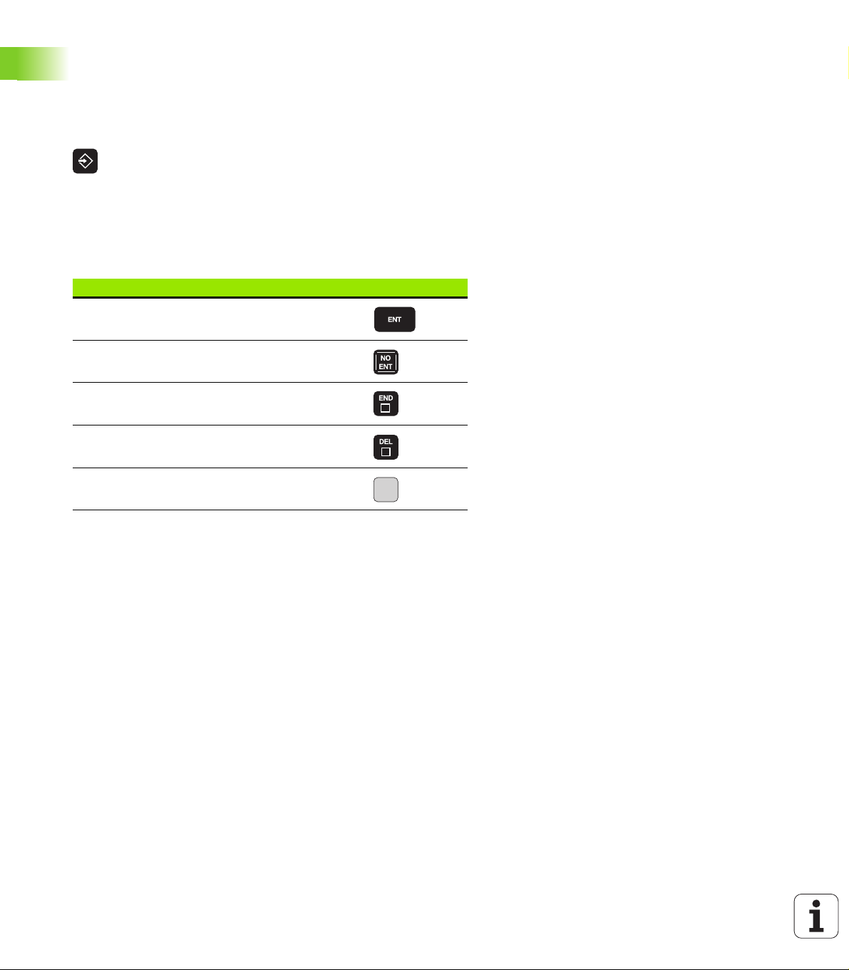
The most important TNC keys
Functions for conversational guidance Key
Confirm entry and activate the next dialog
prompt
Ignore the dialog question.
1.3 Programming the First Part
End the dialog immediately.
Abort dialog, discard entries.
Soft keys on the screen with which you select
functions appropriate to the active state
Further information on this topic
Writing and editing programs: See “Editing a program” on page 109
Overview of keys: See “Controls of the TNC” on page 2
54 First Steps with the iTNC 530
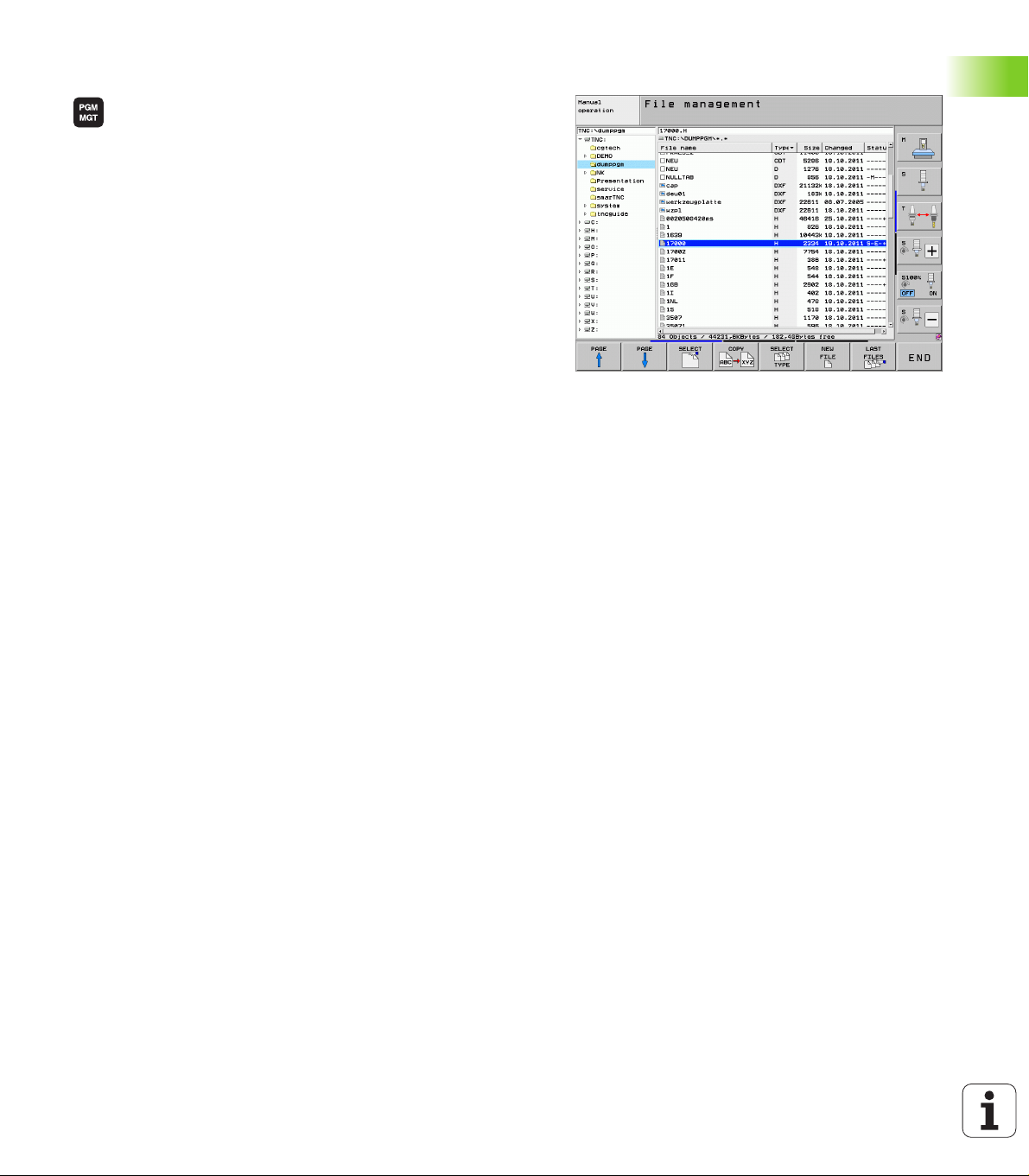
Create a new program/file management
U Press the PGM MGT key: the TNC displays the file
management. The file management of the TNC is
arranged much like the file management on a PC with
the Windows Explorer. The file management enables
you to manipulate data on the TNC hard disk
U Use the arrow keys to select the folder in which you
want to open the new file
U Enter a file name with the extension .H: The TNC then
automatically opens a program and asks for the unit
of measure for the new program. Please note the
restrictions regarding special characters in the file
name (see “File names” on page 116)
U To select the unit of measure, press the MM or INCH
soft key: The TNC automatically starts the workpiece
blank definition (see “Define a workpiece blank” on
page 56)
The TNC automatically generates the first and last blocks of the
program. Afterwards you can no longer change these blocks.
Further information on this topic
File management: See “Working with the File Manager” on page
118
Creating a new program: See “Creating and Writing Programs” on
page 103
1.3 Programming the First Part
HEIDENHAIN iTNC 530 55

Define a workpiece blank
Y
X
Z
MAX
MIN
-40
100
100
0
0
Immediately after you have created a new program, the TNC starts the
dialog for entering the workpiece blank definition. Always define the
workpiece blank as a cuboid by entering the MIN and MAX points,
each with reference to the selected reference point.
After you have created a new program, the TNC automatically initiates
the workpiece blank definition and asks for the required data:
U Spindle axis Z?: Enter the active spindle axis. Z is saved as default
setting. Accept with the ENT key
U Def BLK FORM: Min-corner?: Smallest X coordinate of the workpiece
blank with respect to the reference point, e.g. 0. Confirm with the
ENT key
U Def BLK FORM: Min-corner?: Smallest Y coordinate of the workpiece
blank with respect to the reference point, e.g. 0. Confirm with the
ENT key
U Def BLK FORM: Min-corner?: Smallest Z coordinate of the workpiece
blank with respect to the reference point, e.g. -40. Confirm with the
ENT key
U Def BLK FORM: Max-corner?: Largest X coordinate of the workpiece
1.3 Programming the First Part
blank with respect to the reference point, e.g. 100. Confirm with the
ENT key
U Def BLK FORM: Max-corner?: Largest Y coordinate of the workpiece
blank with respect to the reference point, e.g. 100. Confirm with the
ENT key
U Def BLK FORM: Max-corner?: Largest Z coordinate of the workpiece
blank with respect to the reference point, e.g. 0. Confirm with the
ENT key
Example NC blocks
0 BEGIN PGM NEW MM
1 BLK FORM 0.1 Z X+0 Y+0 Z-40
2 BLK FORM 0.2 X+100 Y+100 Z+0
3 END PGM NEW MM
Further information on this topic
Defining the workpiece blank: (see page 104)
56 First Steps with the iTNC 530

Program layout
NC programs should be arranged consistently in a similar manner. This
makes it easier to find your place and reduces errors.
Recommended program layout for simple, conventional contour
machining
1 Call tool, define tool axis
2 Retract the tool
3 Pre-position the tool in the working plane near the contour starting
point
4 In the tool axis, position the tool above the workpiece, or pre-
position immediately to workpiece depth. If required, switch on
the spindle/coolant
5 Move to the contour
6 Machine the contour
7 Leave the contour
8 Retract the tool, end the program
Further information on this topic:
Contour programming: See “Tool Movements” on page 214
Recommended program layout for simple cycle programs
1 Call tool, define tool axis
2 Retract the tool
3 Define the machining positions
4 Define the fixed cycle
5 Call the cycle, switch on the spindle/coolant
6 Retract the tool, end the program
Further information on this topic:
Cycle programming: See User’s Manual for Cycles
Example: Layout of contour machining programs
0 BEGIN PGM BSPCONT MM
1 BLK FORM 0.1 Z X... Y... Z...
2 BLK FORM 0.2 X... Y... Z...
3 TOOL CALL 5 Z S5000
4 L Z+250 R0 FMAX
5 L X... Y... R0 FMAX
6 L Z+10 R0 F3000 M13
7 APPR ... RL F500
...
16 DEP ... X... Y... F3000 M9
17 L Z+250 R0 FMAX M2
18 END PGM BSPCONT MM
Example: Cycle program layout
0 BEGIN PGM BSBCYC MM
1 BLK FORM 0.1 Z X... Y... Z...
2 BLK FORM 0.2 X... Y... Z...
3 TOOL CALL 5 Z S5000
4 L Z+250 R0 FMAX
5 PATTERN DEF POS1( X... Y... Z... ) ...
6 CYCL DEF...
7 CYCL CALL PAT FMAX M13
8 L Z+250 R0 FMAX M2
9 END PGM BSBCYC MM
1.3 Programming the First Part
HEIDENHAIN iTNC 530 57
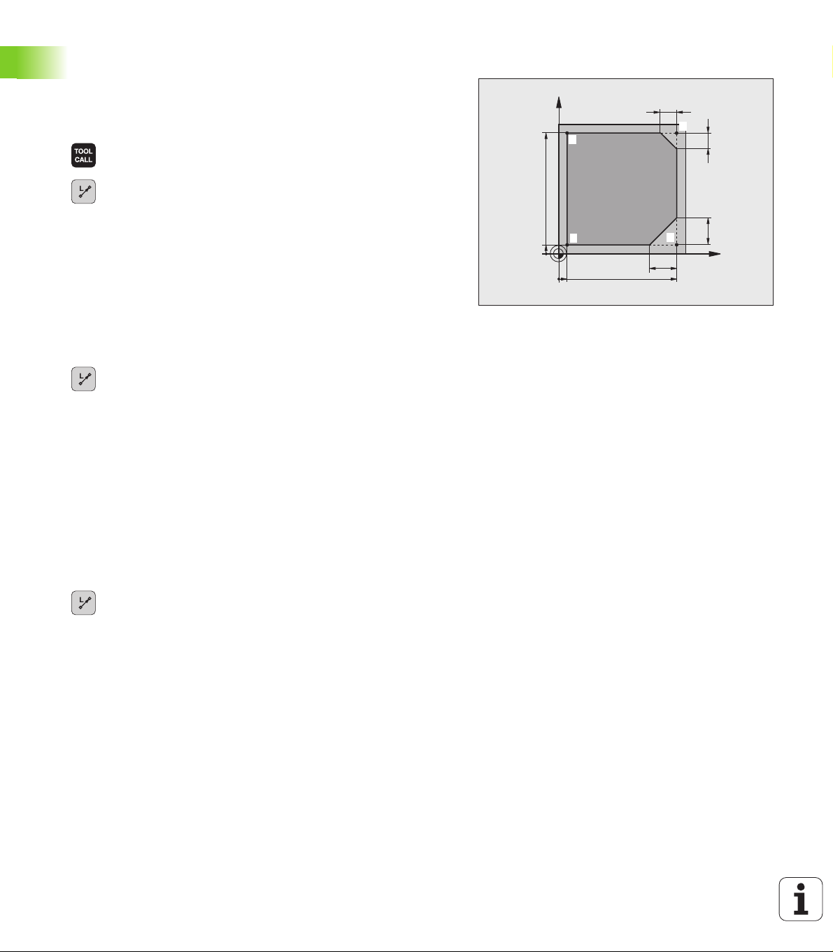
Program a simple contour
X
Y
9
5
95
5
10
10
20
20
1
4
2
3
The contour shown to the right is to be milled once to a depth of 5 mm.
You have already defined the workpiece blank. After you have initiated
a dialog through a function key, enter all the data requested by the
TNC in the screen header.
U Call the tool: Enter the tool data. Confirm each of your
entries with the ENT key. Do not forget the tool axis
U Retract the tool: Press the orange axis key Z in order
to get clear in the tool axis, and enter the value for the
position to be approached, e.g. 250. Confirm with the
ENT key
U Confirm Radius comp.: RL/RR/no comp? by pressing
the ENT key: Do not activate the radius compensation
U Confirm Feed rate F=? with the ENT key: Move at
rapid traverse (FMAX)
U Confirm the Miscellaneous function M? with the
END key: The TNC saves the entered positioning
block
1.3 Programming the First Part
U Preposition the tool in the working plane: Press the
orange X axis key and enter the value for the position
to be approached, e.g. -20
U Press the orange Y axis key and enter the value for the
position to be approached, e.g. -20. Confirm with the
ENT key
U Confirm Radius comp.: RL/RR/no comp? by pressing
the ENT key: Do not activate the radius compensation
U Confirm Feed rate F=? with the ENT key: Move at
rapid traverse (FMAX)
U Confirm the Miscellaneous function M? with the
END key: The TNC saves the entered positioning
block
U Move the tool to workpiece depth: Press the orange Y
axis key and enter the value for the position to be
approached, e.g. -5. Confirm with the ENT key
U Confirm Radius comp.: RL/RR/no comp? by pressing
the ENT key: Do not activate the radius compensation
U Feed rate F=? Enter the positioning feed rate, e.g.
3000 mm/min and confirm with the ENT key
U Miscellaneous function M? Switch on the spindle and
coolant, e.g. M13. Confirm with the END key: The TNC
saves the entered positioning block
58 First Steps with the iTNC 530
U Move to the contour: Press the APPR/DEP key: The
TNC shows a soft-key row with approach and
departure functions
U Select the approach function APPR CT: Enter the
coordinates of the contour starting point 1 in X and Y,
e.g. 5/5. Confirm with the ENT key
U Center angle? Enter the approach angle, e.g.90°, and
confirm with the ENT key
U Circle radius? Enter the approach radius, e.g. 8 mm,
and confirm with the ENT key
U Confirm the Radius comp.: RL/RR/no comp? with the
RL soft key: Activate the radius compensation to the
left of the programmed contour
U Feed rate F=? Enter the machining feed rate, e.g.
700 mm/min, and confirm your entry with the END
key
U Machine the contour and move to contour point 2: You
only need to enter the information that changes. In
other words, enter only the Y coordinate 95 and save
your entry with the END key
U Move to contour point 3: Enter the X coordinate 95
and save your entry with the END key
U Define the chamfer at contour point 3: Enter the
chamfer width 10 mm and save with the END key
U Move to contour point 4: Enter the Y coordinate 5 and
save your entry with the END key
U Define the chamfer at contour point 4: Enter the
chamfer width 20 mm and save with the END key
U Move to contour point 1: Enter the X coordinate 5 and
save your entry with the END key
1.3 Programming the First Part
HEIDENHAIN iTNC 530 59

U Contour departure
U Select the departure function DEP CT
U Center angle? Enter the departure angle, e.g. 90°, and
confirm with the ENT key
U Circle radius? Enter the departure radius, e.g. 8 mm,
and confirm with the ENT key
U Feed rate F=? Enter the positioning feed rate, e.g.
3000 mm/min and confirm with the ENT key
U Miscellaneous function M? Switch off the coolant,
e.g. M9, with the END key: The TNC saves the entered
positioning block
U Retract the tool: Press the orange axis key Z in order
to get clear in the tool axis, and enter the value for the
position to be approached, e.g. 250. Confirm with the
ENT key
U Confirm Radius comp.: RL/RR/no comp? by pressing
the ENT key: Do not activate the radius compensation
1.3 Programming the First Part
U Confirm Feed rate F=? with the ENT key: Move at
rapid traverse (FMAX)
U Miscellaneous function M? Enter M2 to end the
program and confirm with the END key: The TNC
saves the entered positioning block
Further information on this topic
Complete example with NC blocks: See “Example: Linear
movements and chamfers with Cartesian coordinates” on page 236
Creating a new program: See “Creating and Writing Programs” on
page 103
Approaching/departing contours: See “Contour Approach and
Departure” on page 219
Programming contours: See “Overview of path functions” on page
227
Programmable feed rates: See “Possible feed rate input” on page
107
Tool radius compensation: See “Tool radius compensation” on page
209
Miscellaneous functions (M): See “Miscellaneous Functions for
Program Run Control, Spindle and Coolant” on page 369
60 First Steps with the iTNC 530

Create a cycle program
X
Y
20
10
100
100
10
90
9080
The holes (depth of 20 mm) shown in the figure at right are to be drilled
with a standard drilling cycle. You have already defined the workpiece
blank.
U Call the tool: Enter the tool data. Confirm each of your
entries with the ENT key. Do not forget the tool axis
U Retract the tool: Press the orange axis key Z in order
to get clear in the tool axis, and enter the value for the
position to be approached, e.g. 250. Confirm with the
ENT key
U Confirm Radius comp.: RL/RR/no comp? by pressing
the ENT key: Do not activate the radius compensation
U Confirm Feed rate F=? with the ENT key: Move at
rapid traverse (FMAX)
U Confirm the Miscellaneous function M? with the
END key: The TNC saves the entered positioning
block
U Call the cycle menu
U Display the drilling cycles
U Select the standard drilling cycle 200: The TNC starts
the dialog for cycle definition. Enter all parameters
requested by the TNC step by step and conclude each
entry with the ENT key. In the screen to the right, the
TNC also displays a graphic showing the respective
cycle parameter
1.3 Programming the First Part
HEIDENHAIN iTNC 530 61

U Call the menu for special functions
U Display the functions for point machining
U Select the pattern definition
U Select point entry: Enter the coordinates of the
4 points and confirm each with the ENT key. After
entering the fourth point, save the block with the END
key
U Display the menu for defining the cycle call
U Run the drilling cycle on the define pattern:
U Confirm Feed rate F=? with the ENT key: Move at
rapid traverse (FMAX)
U Miscellaneous function M? Switch on the spindle and
coolant, e.g. M13. Confirm with the END key: The TNC
saves the entered positioning block
U Retract the tool: Press the orange axis key Z in order
1.3 Programming the First Part
to get clear in the tool axis, and enter the value for the
position to be approached, e.g. 250. Confirm with the
ENT key
U Confirm Radius comp.: RL/RR/no comp? by pressing
the ENT key: Do not activate the radius compensation
U Confirm Feed rate F=? with the ENT key: Move at
rapid traverse (FMAX)
U Miscellaneous function M? Enter M2 to end the
program and confirm with the END key: The TNC
saves the entered positioning block
62 First Steps with the iTNC 530

Example NC blocks
0 BEGIN PGM C200 MM
1 BLK FORM 0.1 Z X+0 Y+0 Z-40
2 BLK FORM 0.2 X+100 Y+100 Z+0
3 TOOL CALL 5 Z S4500
4 L Z+250 R0 FMAX
5 PATTERN DEF
POS1 (X+10 Y+10 Z+0)
POS2 (X+10 Y+90 Z+0)
POS3 (X+90 Y+90 Z+0)
POS4 (X+90 Y+10 Z+0)
6 CYCL DEF 200 DRILLING
Q200=2 ;SETUP CLEARANCE
Q201=-20 ;DEPTH
Q206=250 ;FEED RATE FOR PLNGN
Q202=5 ;PLUNGING DEPTH
Q210=0 ;DWELL TIME AT TOP
Q203=-10 ;SURFACE COORDINATE
Q204=20 ;2ND SETUP CLEARANCE
Q211=0.2 ;DWELL TIME AT DEPTH
7 CYCL CALL PAT FMAX M13
8 L Z+250 R0 FMAX M2
9 END PGM C200 MM
Definition of workpiece blank
Tool call
Retract the tool
Define the machining positions.
Define the cycle
1.3 Programming the First Part
Spindle and coolant on, call cycle
Retract in the tool axis, end program
Further information on this topic
Creating a new program: See “Creating and Writing Programs” on
page 103
Cycle programming: See User’s Manual for Cycles
HEIDENHAIN iTNC 530 63
1.4 Graphically Testing the First
Program
Selecting the correct operating mode
You can test programs only in the Test Run mode:
U Press the operating modes key: The TNC goes into
the Test Run mode
Further information on this topic
Operating modes of the TNC: See “Operating Modes” on page 78
Testing programs: See “Test Run” on page 621
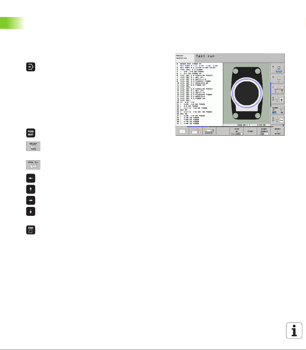
Select the tool table for the test run
You only need to execute this step if you have not activated a tool
table in the Test Run mode.
U Press the PGM MGT key: the TNC displays the file
management
U Press the SELECT TYPE soft key: The TNC shows a
soft-key menu for selection of the file type to be
displayed
U Press the SHOW ALL soft key: The TNC shows all
saved files in the right window
1.4 Graphically Testing the First Program
U Move the highlight to the left onto the directories
U Move the highlight to the TNC:\ directory
U Move the highlight to the right onto the files
U Move the highlight to the file TOOL.T (active tool
table) and load with the ENT key: TOOL.T receives
that status S and is therefore active for the Test Run
U Press the END key: Leave the file manager
Further information on this topic
Tool management: See “Entering tool data in the table” on page 176
Testing programs: See “Test Run” on page 621
64 First Steps with the iTNC 530
Choose the program you want to test
U Press the PGM MGT key: The TNC displays the file
manager
U Press the LAST FILES soft key: The TNC opens a
pop-up window with the most recently selected files
U Use the arrow keys to select the program that you
want to test. Load with the ENT key
Further information on this topic
Selecting a program: See “Working with the File Manager” on page
118
Select the screen layout and the view
U Press the key for selecting the screen layout. The TNC
shows all available alternatives in the soft-key row
U Press the PROGRAM + GRAPHICS soft key: In the
left half of the screen the TNC shows the program; in
the right half it shows the workpiece blank
U Select the desired view via soft key
U Plan view
U Projection in three planes
U 3-D view
Further information on this topic
Graphic functions: See “Graphics” on page 610
Running a test run: See “Test Run” on page 621
Start the program test
U Press the RESET + START soft key: The TNC
simulates the active program up to a programmed
break or to the program end
U While the simulation is running you can use the soft
keys to change views.
U Press the STOP soft key: The TNC interrupts the test
run
U Press the START soft key: The TNC resumes the test
run after a break
Further information on this topic
Running a test run: See “Test Run” on page 621
Graphic functions: See “Graphics” on page 610
Adjusting the test speed:See “Setting the speed of the test run” on
page 611
1.4 Graphically Testing the First Program
HEIDENHAIN iTNC 530 65
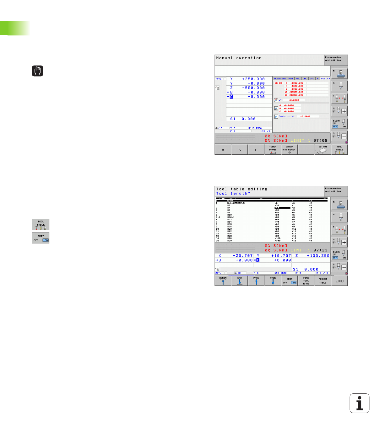
1.5 Tool Setup
Selecting the correct operating mode
Tools are set up in the Manual Operation mode:
U Press the operating modes key: The TNC goes into
the Manual Operation mode
Further information on this topic
1.5 Tool Setup
Operating modes of the TNC: See “Operating Modes” on page 78
Prepare and measure tools
U Clamp the required tools in their chucks
U When measuring with an external tool presetter: Measure the tools,
note down the length and radius, or transfer them directly to the
machine through a transfer program
U When measuring on the machine: Place the tools into the tool
changer (see page 67)
The tool table TOOL.T
In the tool table TOOL.T (permanently saved under TNC:\), save the
tool data such as length and radius, but also further tool-specific
information that the TNC needs to conduct its functions.
To enter tool data in the tool table TOOL.T, proceed as follows:
U Display the tool table
U Edit the tool table: Set the EDITING soft key to ON
U With the upward or downward arrow keys you can
select the tool number that you want to edit
U With the rightward or leftward arrow keys you can
select the tool data that you want to edit
U To leave the tool table, press the END key
Further information on this topic
Operating modes of the TNC: See “Operating Modes” on page 78
Working with the tool table: See “Entering tool data in the table” on
page 176
66 First Steps with the iTNC 530
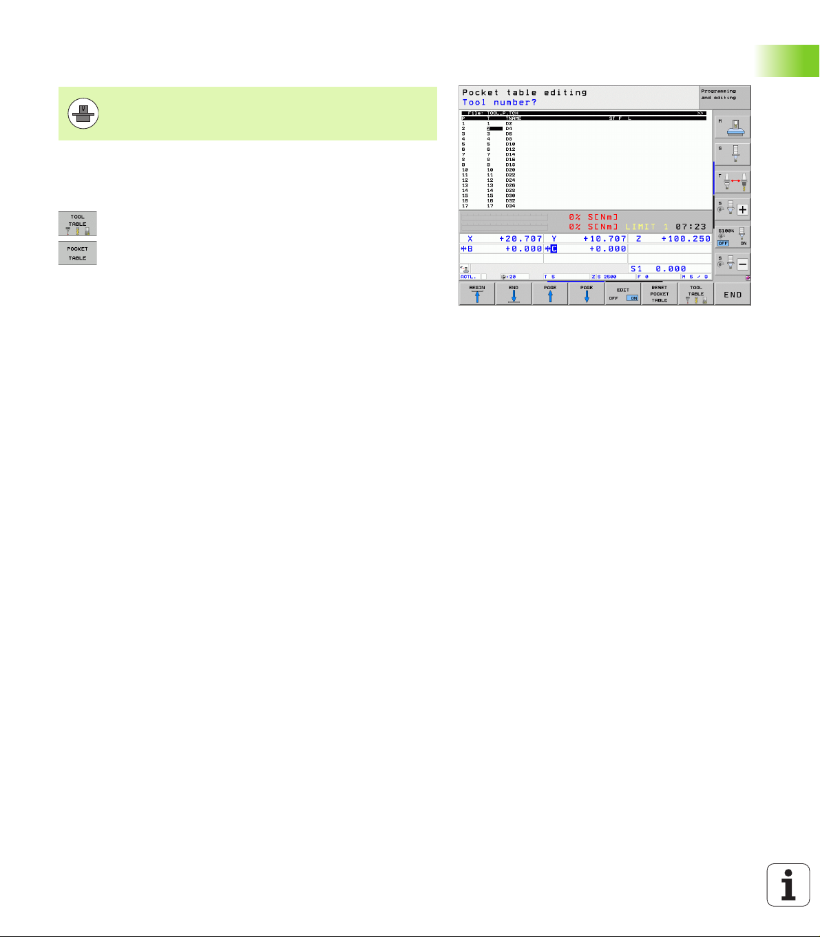
The pocket table TOOL_P.TCH
The function of the pocket table depends on the machine.
Your machine manual provides more detailed information.
In the pocket table TOOL_P.TCH (permanently saved under TNC:\) you
specify which tools your tool magazine contains.
To enter data in the pocket table TOOL_P.TCH, proceed as follows:
U Display the tool table
U Display the pocket table
U Edit the pocket table: Set the EDITING soft key to ON
U With the upward or downward arrow keys you can
select the pocket number that you want to edit
U With the rightward or leftward arrow keys you can
select the data that you want to edit
U To leave the pocket table, press the END key
Further information on this topic
Operating modes of the TNC: See “Operating Modes” on page 78
Working with the pocket table: See “Pocket table for tool changer”
on page 188
1.5 Tool Setup
HEIDENHAIN iTNC 530 67

1.6 Workpiece Setup
Selecting the correct operating mode
Workpieces are set up in the Manual Operation or Electronic
Handwheel mode
U Press the Manual Operation operating mode key: the
TNC switches to that mode.
Further information on this topic
Manual Operation mode: See “Moving the Machine Axes” on page
546
1.6 Workpiece Setup
Clamp the workpiece
Mount the workpiece with a fixture on the machine table. If you have
a 3-D touch probe on your machine, then you do not need to clamp the
workpiece parallel to the axes.
If you do not have a 3-D touch probe available, you have to align the
workpiece so that it is fixed with its edges parallel to the machine
axes.
68 First Steps with the iTNC 530

Align the workpiece with a 3-D touch probe system
U Insert the 3-D touch probe: In the Manual Data Input (MDI) operating
mode, run a TOOL CALL block containing the tool axis, and then return
to the Manual Operation mode (in MDI mode you can run an
individual NC block independently of the others)
U Select the probing functions: The TNC displays the
available functions in the soft-key row
U Measure the basic rotation: The TNC displays the
basic rotation menu. To identify the basic rotation,
probe two points on a straight surface of the
workpiece
U Use the axis-direction keys to pre-position the touch
probe to a position near the first contact point
U Select the probing direction via soft key
U Press NC start: The touch probe moves in the defined
direction until it contacts the workpiece and then
automatically returns to its starting point.
U Use the axis-direction keys to pre-position the touch
probe to a position near the second contact point
U Press NC start: The touch probe moves in the defined
direction until it contacts the workpiece and then
automatically returns to its starting point
U Then the TNC shows the measured basic rotation
U Press the END key to close the menu and then
answer the question of whether the basic rotation
should be transferred to the preset table by pressing
the NO ENT key (no transfer)
1.6 Workpiece Setup
Further information on this topic
MDI operating mode: See “Programming and Executing Simple
Machining Operations” on page 604
Workpiece alignment: See “Compensating Workpiece
Misalignment with a 3-D Touch Probe” on page 581
HEIDENHAIN iTNC 530 69
Set the datum with a 3-D touch probe
U Insert the 3-D touch probe: In the MDI mode, run a TOOL CALL block
containing the tool axis and then return to the Manual Operation
mode
U Select the probing functions: The TNC displays the
available functions in the soft-key row
U Set the reference point at a workpiece corner, for
example: The TNC asks whether the prove points
from the previously measured basic rotation should
be loaded. Press the ENT key to load points
U Position the touch probe at a position near the first
touch point of the side that was not probed for basic
1.6 Workpiece Setup
rotation
U Select the probing direction via soft key
U Press NC start: The touch probe moves in the defined
direction until it contacts the workpiece and then
automatically returns to its starting point
U Use the axis-direction keys to pre-position the touch
probe to a position near the second contact point
U Press NC start: The touch probe moves in the defined
direction until it contacts the workpiece and then
automatically returns to its starting point
U Then the TNC shows the coordinates of the measured
corner point
U Set to 0: Press the SET DATUM soft key
U Press the END to close the menu
Further information on this topic
Datum setting: See “Datum Setting with a 3-D Touch Probe” on
page 587
70 First Steps with the iTNC 530
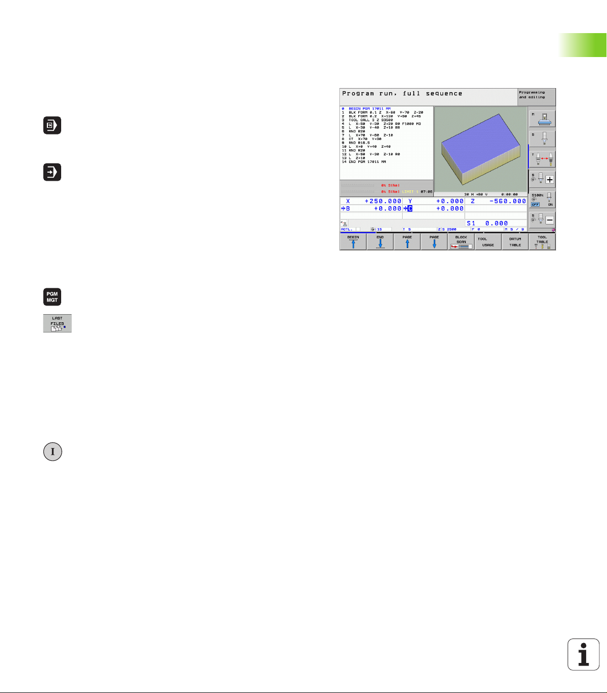
1.7 Running the First Program
Selecting the correct operating mode
You can run programs either in the Single Block or the Full Sequence
mode:
U Press the operating mode key: The TNC goes into the
Program Run, Single Block mode and the TNC
executes the program block by block. You have to
confirm each block with the NC key
U Press the operating mode key: The TNC goes into the
Program Run, Full Sequence mode and the TNC
executes the program after NC start up to a program
break or to the end of the program
Further information on this topic
Operating modes of the TNC: See “Operating Modes” on page 78
Running programs: See “Program Run” on page 627
Choose the program you want to run
U Press the PGM MGT key: The TNC displays the file
manager
U Press the LAST FILES soft key: The TNC opens a pop-
up window with the most recently selected files
U If desired, use the arrow keys to select the program
that you want to run. Load with the ENT key
Further information on this topic
File management: See “Working with the File Manager” on page
118
Start the program
U Press the NC start button: The TNC executes the
active program
Further information on this topic
Running programs: See “Program Run” on page 627
1.7 Running the First Program
HEIDENHAIN iTNC 530 71

1.7 Running the First Program
72 First Steps with the iTNC 530
Introduction

2.1 The iTNC 530
HEIDENHAIN TNC controls are workshop-oriented contouring
controls that enable you to program conventional machining
operations right at the machine in an easy-to-use conversational
programming language. They are designed for milling, drilling and
boring machines, as well as for machining centers. The iTNC 530 can
control up to 18 axes. You can also change the angular position of up
to 2 spindles under program control.
An integrated hard disk provides storage for as many programs as you
like, even if they were created off-line. For quick calculations you can
2.1 The iTNC 530
call up the on-screen pocket calculator at any time.
Keyboard and screen layout are clearly arranged in such a way that the
functions are fast and easy to use.
Programming: HEIDENHAIN conversational, smarT.NC and ISO formats
The HEIDENHAIN conversational programming format is an especially
easy method of writing programs. Interactive graphics illustrate the
individual machining steps for programming the contour. If a
production drawing is not dimensioned for NC, the FK free contour
programming performs the necessary calculations automatically.
Workpiece machining can be graphically simulated either during or
before actual machining.
The smarT.NC operating mode offers TNC beginners an especially
simple possibility to quickly and without much training create
structured conversational dialog programs. Separate user
documentation is available for smarT.NC.
It is also possible to program the TNCs in ISO format or DNC mode.
You can also enter and test one program while the control is running
another.
Compatibility
The TNC can run all part programs that were written on HEIDENHAIN
controls TNC 150 B and later. In as much as old TNC programs contain
OEM cycles, the iTNC 530 must be adapted to them with the PC
software CycleDesign. For more information, contact your machine
tool builder or HEIDENHAIN.
74 Introduction
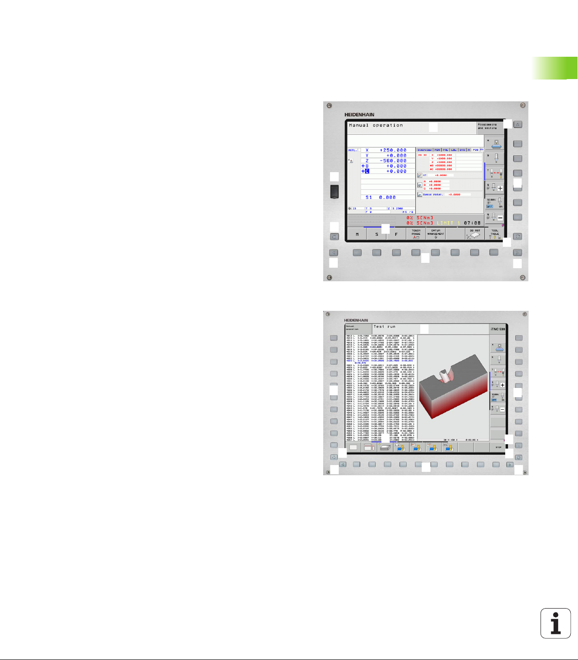
2.2 Visual Display Unit and
131
1
4
4
5
1
678
2
191
3
4
4
5
1
6
7
8
2
1
1
7
Keyboard
Visual display unit
The TNC is shipped with a 15-inch color flat-panel screen. A 19-inch
color flat-panel screen is also available as an alternative.
1 Header
When the TNC is on, the selected operating modes are shown in
the screen header: the machining mode at the left and the
programming mode at right. The currently active mode is
displayed in the larger box, where the dialog prompts and TNC
messages also appear (unless the TNC is showing only graphics).
2 Soft keys
In the footer the TNC indicates additional functions in a soft-key
row. You can select these functions by pressing the keys
immediately below them. The lines immediately above the softkey row indicate the number of soft-key rows that can be called
with the black arrow keys to the right and left. The active soft-key
row is indicated by brightened bar.
The15-inch screen has 8 soft keys, the 19-inch screen has 10 soft
keys.
3 Soft-key selection keys
4 Shifts between soft-key rows
5 Setting the screen layout
6 Shift key for switchover between machining and programming
modes
7 Soft-key selection keys for machine tool builder soft keys
The15-inch screen has 6 soft keys, the 19-inch screen has 18 soft
keys.
8 Switches soft-key rows for machine tool builders
2.2 Visual Display Unit and Keyboard
HEIDENHAIN iTNC 530 75

Sets the screen layout
You select the screen layout yourself: In the PROGRAMMING AND
EDITING mode of operation, for example, you can have the TNC show
program blocks in the left window while the right window displays
programming graphics. You could also display the program structure
in the right window instead, or display only program blocks in one large
window. The available screen windows depend on the selected
operating mode.
To change the screen layout:
Press the SPLIT SCREEN key: The soft-key row
shows the available layout options (see "Operating
Modes", page 78)
Select the desired screen layout.
2.2 Visual Display Unit and Keyboard
76 Introduction

Operating panel
1
2
3
5
1
4
6
77
1
79
8
1
2
3
5
1
4
6
77
1798
1
10
The TNC is delivered with different keyboards. The figures show the
controls and displays of the TE 730 (15") and TE 740 (19") keyboard
units.
1 Alphabetic keyboard for entering texts and file names, and for ISO
programming.
Dual-processor version: Additional keys for Windows operation
2 File management
Calculator
MOD function
HELP function
3 Programming modes
4 Machine operating modes
5 Initiation of programming dialog
6 Navigation keys and GOTO jump command
7 Numerical input and axis selection
8 Touchpad
9 smarT.NC navigation keys
10 USB connection
The functions of the individual keys are described on the inside front
cover.
Some machine manufacturers do not use the standard
operating panel from HEIDENHAIN. Please refer to your
machine manual in these cases.
Machine panel buttons, e.g. NC START or NC STOP, are
also described in the manual for your machine tool.
2.2 Visual Display Unit and Keyboard
HEIDENHAIN iTNC 530 77

2.3 Operating Modes
Manual Operation and Electronic Handwheel
The Manual Operation mode is required for setting up the machine
tool. In this mode of operation, you can position the machine axes
manually or by increments, set the datums, and tilt the working plane.
The Electronic Handwheel mode of operation allows you to move the
machine axes manually with the HR electronic handwheel.
Soft keys for selecting the screen layout (select as described
previously)
Window Soft key
2.3 Operating Modes
Positions
Left: positions, right: status display
Left: positions, right: active collision objects
(FCL4 function).
Positioning with Manual Data Input
This mode of operation is used for programming simple traversing
movements, such as for face milling or pre-positioning.
Soft keys for selecting the screen layout
Window Soft key
Program
Left: program blocks, right: status display
Left: program blocks, right: active collision
objects (FCL4 function). If this view is selected,
then the TNC indicates a collision with a red
frame around the graphics window.
78 Introduction

Programming and Editing
In this mode of operation you can write your part programs. The FK
free programming feature, the various cycles and the Q parameter
functions help you with programming and add necessary information.
If desired, the programming graphics or the 3-D line graphics (FCL 2
function) display the programmed traverse paths.
Soft keys for selecting the screen layout
Window Soft key
Program
Left: program, right: program structure
Left: program blocks, right: graphics
Left: program blocks, right: 3-D line graphics
3-D line graphics
Test Run
In the Test Run mode of operation, the TNC checks programs and
program sections for errors, such as geometrical incompatibilities,
missing or incorrect data within the program or violations of the work
space. This simulation is supported graphically in different display
modes.
With the dynamic collision monitoring (DCM) software option you can
test the program for potential collisions. As during program run, the
TNC takes into account all permanent machine components defined
by the machine manufacturer as well as all measured fixtures.
Soft keys for selecting the screen layout: see "Program Run, Full
Sequence and Program Run, Single Block", page 80.
2.3 Operating Modes
HEIDENHAIN iTNC 530 79
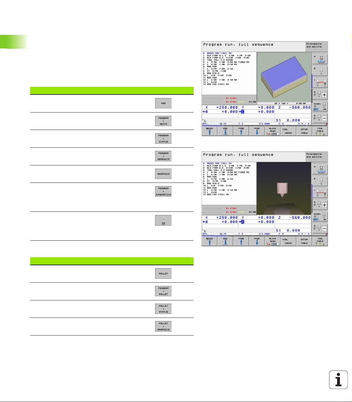
Program Run, Full Sequence and Program Run, Single Block
In the Program Run, Full Sequence mode of operation the TNC
executes a part program continuously to its end or to a manual or
programmed stop. You can resume program run after an interruption.
In the Program Run, Single Block mode of operation you execute each
block separately by pressing the machine START button.
Soft keys for selecting the screen layout
Window Soft key
Program
2.3 Operating Modes
Left: program, right: program structure
Left: program, right: status
Left: program, right: graphics
Graphics
Left: program blocks, right: active collision
objects (FCL4 function). If this view is selected,
then the TNC indicates a collision with a red
frame around the graphics window.
Active collision objects (FCL4 function). If this
view is selected, then the TNC indicates a
collision with a red frame around the graphics
window.
Soft keys for selecting the screen layout for pallet tables
Window Soft key
Pallet table
Left: program blocks, right: pallet table
Left: pallet table, right: status
Left: pallet table, right: graphics
80 Introduction
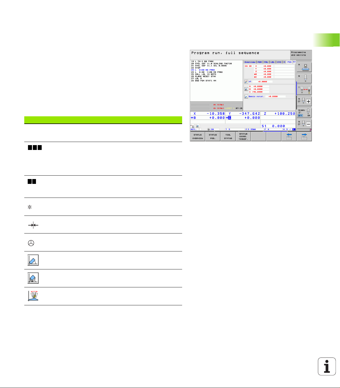
2.4 Status Displays
ACTL.
X Y Z
F S M
“General” status display
The status display in the lower part of the screen informs you of the
current state of the machine tool. It is displayed automatically in the
following modes of operation:
Program Run, Single Block and Program Run, Full Sequence, except
if the screen layout is set to display graphics only, and
Positioning with Manual Data Input (MDI).
In the Manual mode and Electronic Handwheel mode the status
display appears in the large window.
Information in the status display
Symbol Meaning
Actual or nominal coordinates of the current position
Machine axes; the TNC displays auxiliary axes in
lower-case letters. The sequence and quantity of
displayed axes is determined by the machine tool
builder. Refer to your machine manual for more
information.
The displayed feed rate in inches corresponds to one
tenth of the effective value. Spindle speed S, feed
rate F and active M functions.
2.4 Status Displays
Program run started.
Axis is locked.
Axis can be moved with the handwheel.
Axes are moving under a basic rotation.
Axes are moving in a tilted working plane.
The M128 function or TCPM FUNCTION is active.
HEIDENHAIN iTNC 530 81
Symbol Meaning
2.4 Status Displays
The Dynamic Collision Monitoring function (DCM)
is active.
The Adaptive Feed Function (AFC) is active
(software option).
One or more global program settings are active
(software option)
Number of the active presets from the preset table.
If the datum was set manually, the TNC displays the
text MAN behind the symbol.
82 Introduction
Additional status displays
The additional status displays contain detailed information on the
program run. They can be called in all operating modes except for the
Programming and Editing mode of operation.
To switch on the additional status display:
Call the soft-key row for screen layout.
Screen layout with additional status display: In the
right half of the screen, the TNC shows the Overview
status form.
To select an additional status display:
Shift the soft-key rows until the STATUS soft keys
appear.
Either select the additional status display, e.g.
positions and coordinates, or
2.4 Status Displays
use the soft keys to select the desired view.
With the soft keys or switch-over soft keys, you can choose directly
between the available status displays.
Please note that some of the status information described
below is not available unless the associated software
option is enabled on your TNC.
HEIDENHAIN iTNC 530 83
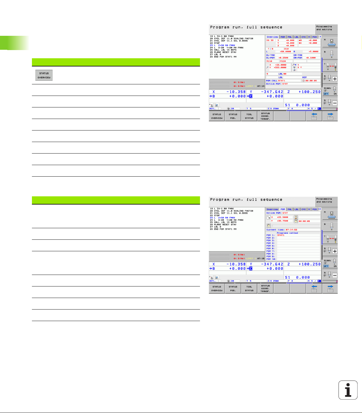
Overview
After switch-on, the TNC displays the Overview status form, provided
that you have selected the PROGRAM+STATUS screen layout (or
POSITION + STATUS). The overview form contains a summary of the
most important status information, which you can also find on the
various detail forms.
Soft key Meaning
Position display in up to 5 axes
Tool information
2.4 Status Displays
General program information (PGM tab)
Soft key Meaning
No direct
selection
possible
Active M functions
Active coordinate transformations
Active subprogram
Active program section repeat
Program called with PGM CALL
Current machining time
Name of the active main program
Name of the active main program
Circle center CC (pole)
Dwell time counter
Machining time when the program was
completely simulated in the Test Run operating
mode
Current machining time in percent
Current time
Current feed rate
Active programs
84 Introduction
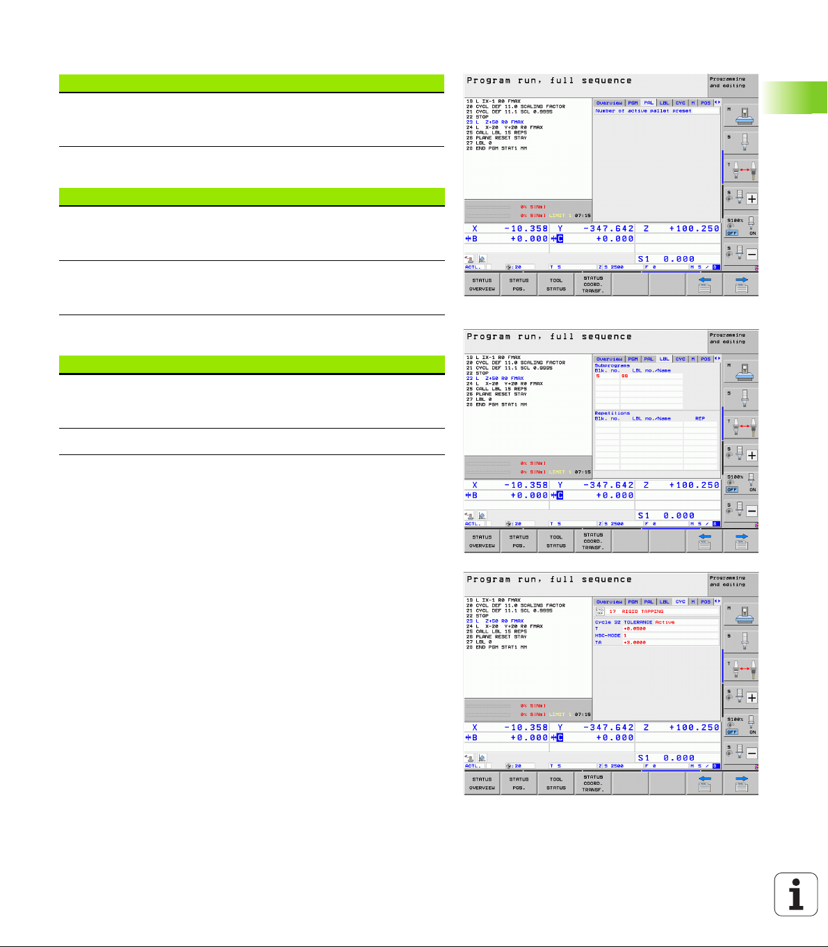
General pallet information (PAL tab)
Soft key Meaning
No direct
selection
possible
Program section repeat/Subprograms (LBL tab)
Soft key Meaning
No direct
selection
possible
Information on standard cycles (CYC tab)
Soft key Meaning
No direct
selection
possible
Number of the active pallet preset
Active program section repeats with block
number, label number, and number of
programmed repeats/repeats yet to be run
Active subprogram numbers with block number in
which the subprogram was called and the label
number that was called
Active machining cycle
Active values of Cycle 32 Tolerance
2.4 Status Displays
HEIDENHAIN iTNC 530 85
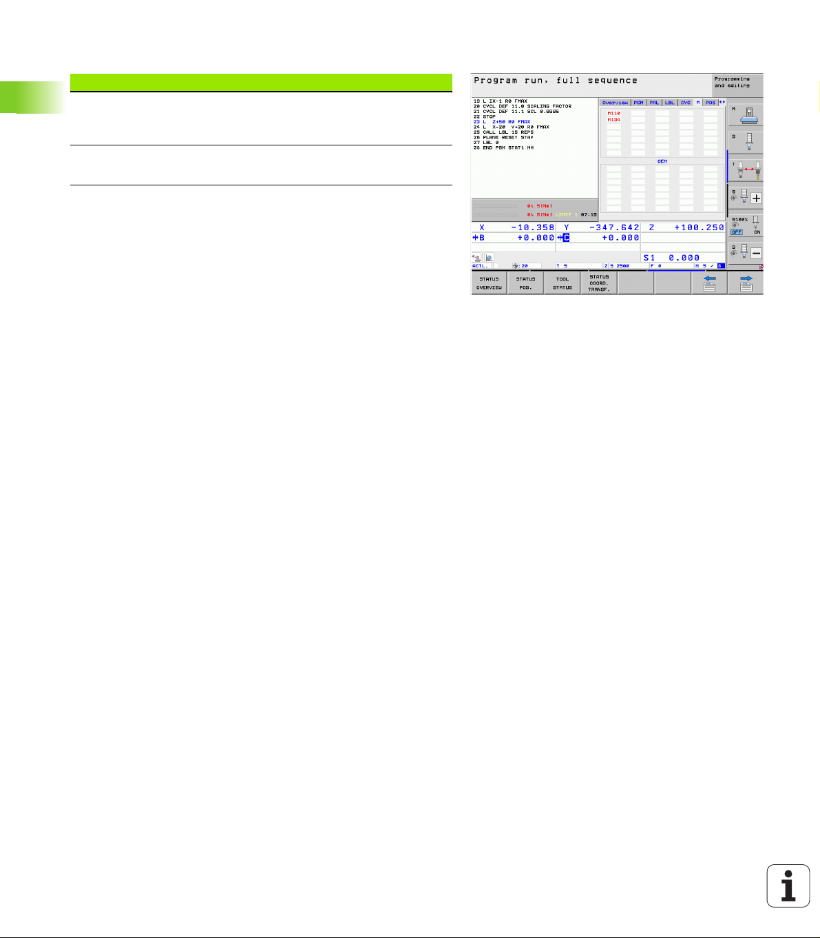
Active miscellaneous functions M (M tab)
Soft key Meaning
No direct
selection
possible
List of the active M functions with fixed meaning
List of the active M functions that are adapted by
your machine manufacturer
2.4 Status Displays
86 Introduction
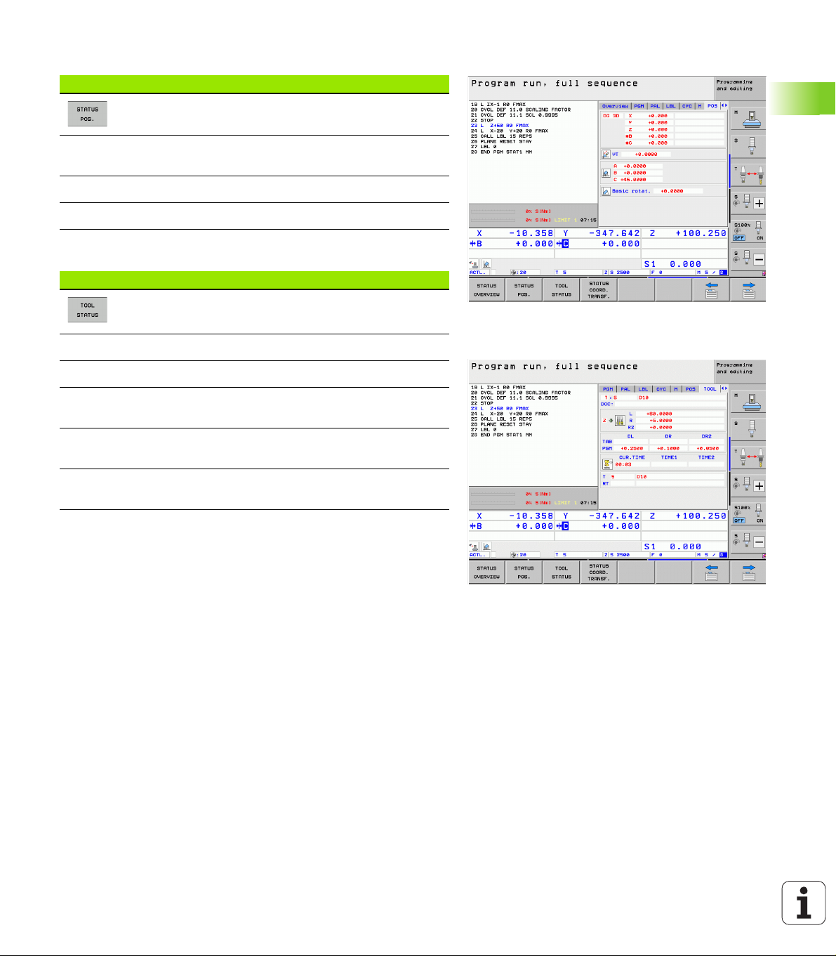
Positions and coordinates (POS tab)
Soft key Meaning
Type of position display, e.g. actual position
Value traversed in virtual axis direction VT (only with
“global program settings” software option)
Tilt angle of the working plane
Angle of a basic rotation
Information on tools (TOOL tab)
Soft key Meaning
T: Tool number and name
RT: Number and name of a replacement tool
Tool axis
Tool lengths and radii
Oversizes (delta values) from the tool table (TAB) and
the TOOL CALL (PGM)
Tool life, maximum tool life (TIME 1) and maximum
tool life for TOOL CALL (TIME 2)
Display of the active tool and the (next) replacement
tool
2.4 Status Displays
HEIDENHAIN iTNC 530 87
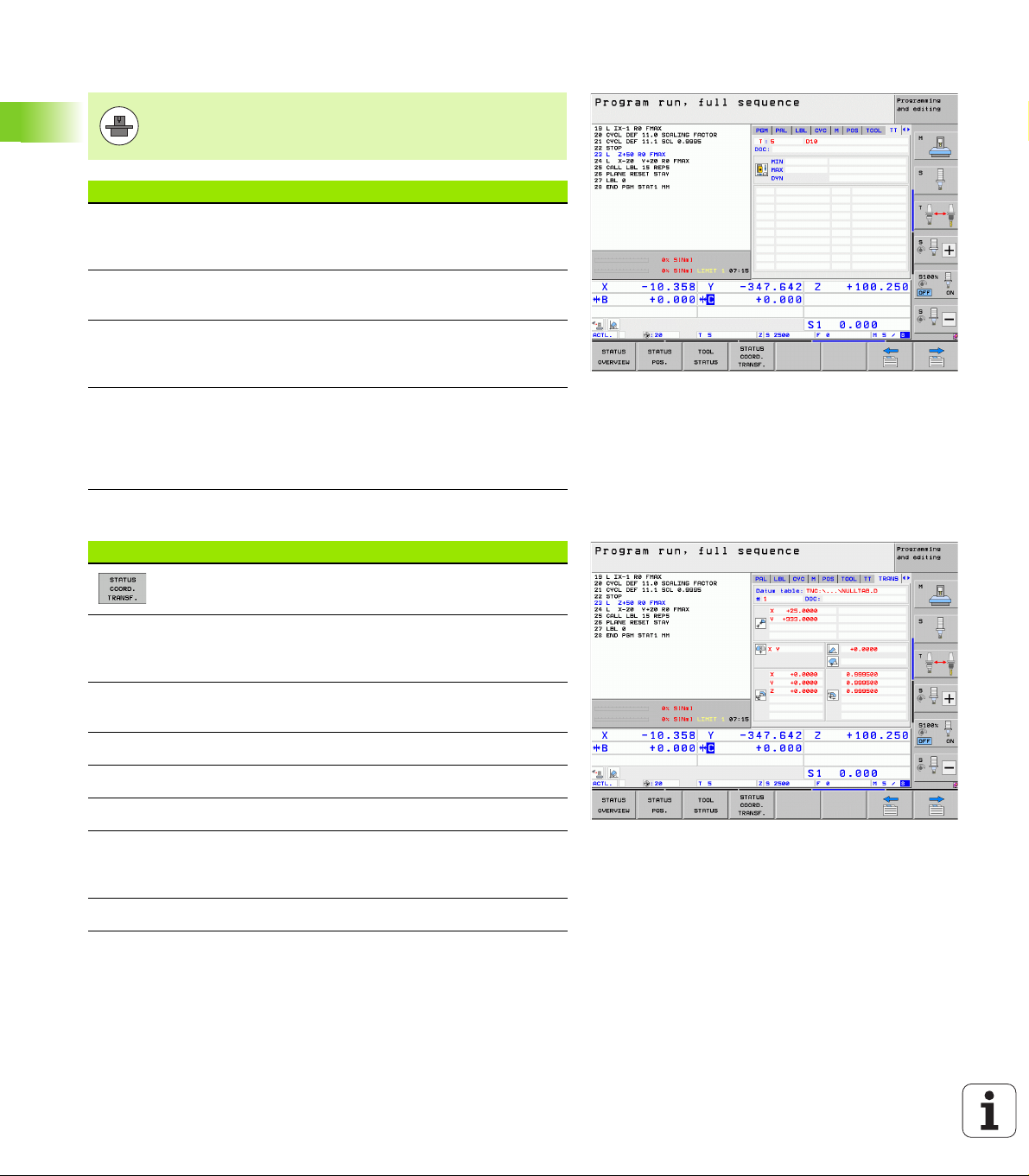
Tool measurement (TT tab)
The TNC only displays the TT tab if the function is active
on your machine.
Soft key Meaning
No direct
selection
possible
Number of the tool to be measured
2.4 Status Displays
Coordinate transformations (TRANS tab)
Soft key Meaning
Display whether the tool radius or the tool length
is being measured
MIN and MAX values of the individual cutting
edges and the result of measuring the rotating
tool (DYN = dynamic measurement)
Cutting edge number with the corresponding
measured value. If the measured value is
followed by an asterisk, the allowable tolerance in
the tool table was exceeded The TNC displays the
measured values of up to 24 teeth.
Name of the active datum table
Active datum number (#), comment from the
active line of the active datum number (DOC) from
Cycle 7
Active datum shift (Cycle 7); The TNC displays an
active datum shift in up to 8 axes
Mirrored axes (Cycle 8)
Active basic rotation
Active rotation angle (Cycle 10)
Active scaling factor/factors (Cycles 11 / 26); The
TNC displays an active scaling factor in up to 6
axes
Scaling datum
For further information, refer to the User's Manual for Cycles,
"Coordinate Transformation Cycles."
88 Introduction
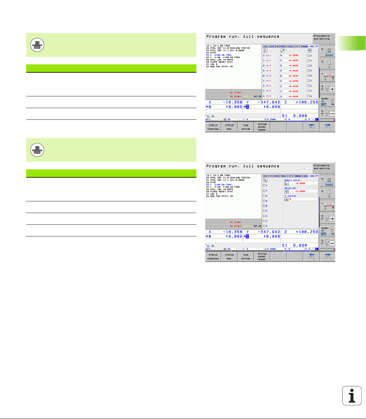
Global program settings 1 (GPS1 tab, software option)
The TNC only displays the tab if the function is active on
your machine.
Soft key Meaning
No direct
selection
possible
Swapped axes
Superimposed datum shift
Superimposed mirroring
Global program settings 2 (GPS2 tab, software option)
The TNC only displays the tab if the function is active on
your machine.
Soft key Meaning
No direct
selection
possible
Locked axes
Superimposed basic rotation
Superimposed rotation
Active feed rate factor
2.4 Status Displays
HEIDENHAIN iTNC 530 89

Adaptive Feed Control (AFC tab, software option)
The TNC only displays the AFC tab if the function is active
on your machine.
Soft key Meaning
No direct
selection
possible
Active mode in which adaptive feed control is
running
2.4 Status Displays
Active tool (number and name)
Cut number
Current factor of the feed potentiomenter in
percent
Active spindle load in percent
Reference load of the spindle
Current spindle speed
Current deviation of the speed
Current machining time
Line diagram, in which the current spindle load
and the value commanded by the TNC for the
feed-rate override are shown
90 Introduction

2.5 Window Manager
The machine tool builder determines the scope of function
and behavior of the window manager. The machine tool
manual provides further information.
The TNC features the Xfce window manager. Xfce is a standard
application for UNIX-based operating systems, and is used to manage
graphical user interfaces. The following functions are possible with the
window manager:
Display a task bar for switching between various applications (user
interfaces).
Manage an additional desktop, on which special applications from
your machine tool builder can run.
Control the focus between NC-software applications and those of
the machine tool builder.
The size and position of pop-up windows can be changed. It is also
possible to close, minimize and restore the pop-up windows.
The TNC shows a star in the upper left of the screen if an
application of the window manager or the window
manager itself has caused an error. In this case, switch to
the window manager and correct the problem. If required,
refer to your machine manual.
2.5 Window Manager
HEIDENHAIN iTNC 530 91

Soft-key row
In the task bar you can choose different workspaces by mouse click.
The iTNC provides the following workspaces:
Workspace 1: Active mode of operation
Workspace 2: Active programming mode
Workspace 3: Manufacturer's applications (optionally available), e.g.
remote control of a Windows computer
In the task bar you can also select other applications that you have
started together with the TNC (switch for example to the PDF viewer
or TNCguide)
Click the green HEIDENHAIN symbol to open a menu in which you can
get information, make settings or start applications. The following
2.5 Window Manager
functions are available:
About Xfce: Information on the Windows manager Xfce
About HeROS: Information about the operation system of the TNC
NC Control: Start and stop the TNC software. Only permitted for
diagnostic purposes
Web Browser: Start Mozilla Firefox
Diagnostics: Available only to authorized specialists to start
diagnostic functions
Settings: Configuration of miscellaneous settings
Date/Time: Set the date and time
Language: Language setting for the system dialogs. During startup
the TNC overwrites this setting with the language setting of
MP 7230
Network: Network setting
Reset WM-Conf: Restore basic settings of the Windows Manager
May also reset settings implemented by your machine
manufacturer
Screensaver: Settings for the screen saver; several are available
Shares: Configure network connections
Tools: Only for authorized users. The applications available under
Tools can be started directly by selecting the pertaining file type in
the file management of the TNC (see “Additional tools for
management of external file types” on page 139)
92 Introduction

2.6 SELinux security software
SELinux is an extension for Linux-based operating systems. SELinux
is an additional security software package based on Mandatory
Access Control (MAC) and protects the system against the running of
unauthorized processes or functions and therefore protects against
viruses and other malware.
MAC means that each action must be specifically permitted otherwise
the TNC will not run it. The software provides additional protection to
the normal access restrictions of Linux. Specific processes and
actions are performed only if permitted by the standard functions and
SELinux access control.
The SELinux installation of the TNC is prepared to permit
running of only those programs installed with the
HEIDENHAIN NC software. You cannot run other
programs with the standard installation.
The SELinux access control in HeROS 5 is regulated as follows:
The TNC runs only those applications installed with the
HEIDENHAIN NC software.
Files concerning the security of the software (SELinux system files,
HeROS 5 boot files, etc.) may only be changed by explicitly selected
programs.
Files created anew by other programs must basically not be run.
There are only two procedures permitted to run new files:
Starting a software update
A HEIDENHAIN software update can replace or change system
files.
Starting the SELinux configuration
The configuration of SELinux is usually password-protected by
your machine tool builder. Refer here to the relevant machine tool
manual.
2.6 SELinux security software
HEIDENHAIN basically recommends activating SELinux,
because this provides additional protection against
external access.
HEIDENHAIN iTNC 530 93
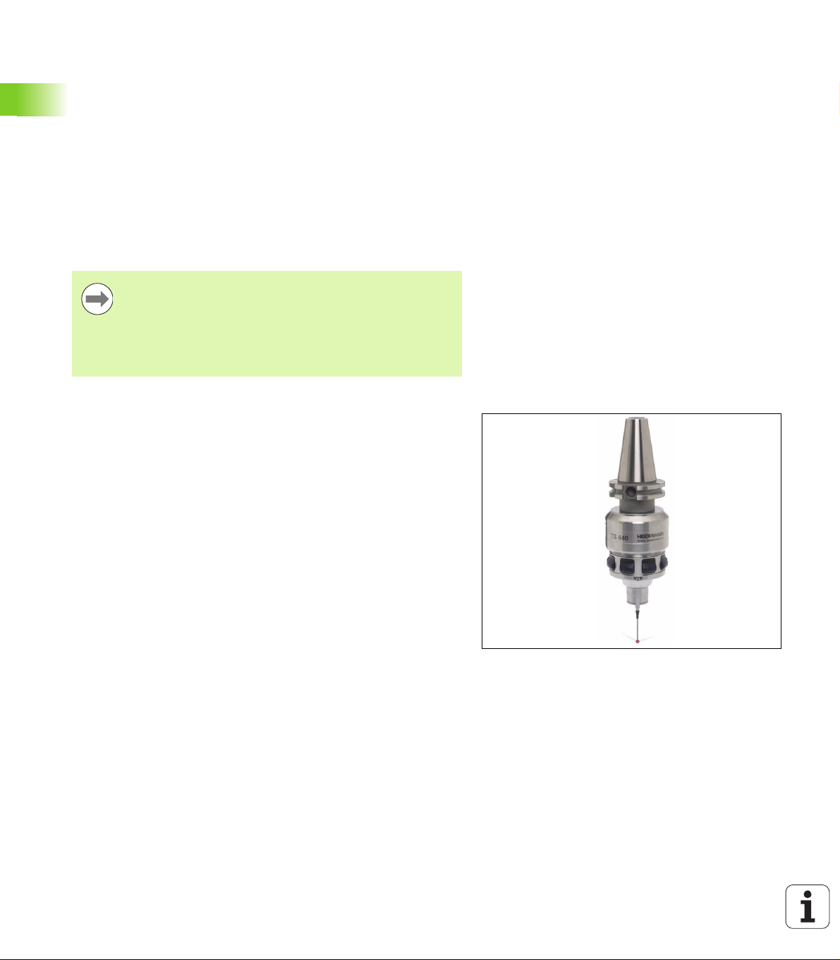
2.7 Accessories: HEIDENHAIN 3-D
Touch Probes and Electronic
Handwheels
3-D touch probes
With the various HEIDENHAIN 3-D touch probe systems you can:
Automatically align workpieces
Quickly and precisely set datums
Measure the workpiece during program run
Measure and inspect tools
All of the touch probe functions are described in the
User’s Manual for Cycles. Please contact HEIDENHAIN if
you require a copy of this User’s Manual. ID: 670 388-xx.
Note that HEIDENHAIN generally does not accept liability
for the function of the touch probe cycles unless you use
HEIDENHAIN touch probes!
TS 220, TS 640 and TS 440 touch trigger probes
These touch probes are particularly effective for automatic workpiece
alignment, datum setting and workpiece measurement. The TS 220
transmits the triggering signals to the TNC via cable and is a costeffective alternative for applications where digitizing is not frequently
required.
The TS 640 (see figure) and the smaller TS 440 feature infrared
transmission of the triggering signal to the TNC. This makes them
highly convenient for use on machines with automatic tool changers.
Principle of operation: HEIDENHAIN triggering touch probes feature a
wear resisting optical switch that generates an electrical signal as
soon as the stylus is deflected. This signal is transmitted to the
control, which stores the current position of the stylus as the actual
value.
2.7 Accessories: HEIDENHAIN 3-D Touch Probes and Electronic Handwheels
94 Introduction

TT 140 tool touch probe for tool measurement
The TT 140 is a triggering 3-D touch probe for tool measurement and
inspection. Your TNC provides three cycles for this touch probe with
which you can measure the tool length and radius automatically either
with the spindle rotating or stopped. The TT 140 features a particularly
rugged design and a high degree of protection, which make it
insensitive to coolants and swarf. The triggering signal is generated by
a wear-resistant and highly reliable optical switch.
HR electronic handwheels
Electronic handwheels facilitate moving the axis slides precisely by
hand. A wide range of traverses per handwheel revolution is available.
Apart from the HR130 and HR150 integral handwheels, HEIDENHAIN
also offers the HR 520 and HR 550 FS portable handwheels. You will
find a detailed description of HR 520 in Chapter 14 of this manual (see
“Traversing with electronic handwheels” on page 548).
HEIDENHAIN iTNC 530 95
2.7 Accessories: HEIDENHAIN 3-D Touch Probes and Electronic Handwheels

2.7 Accessories: HEIDENHAIN 3-D Touch Probes and Electronic Handwheels
96 Introduction
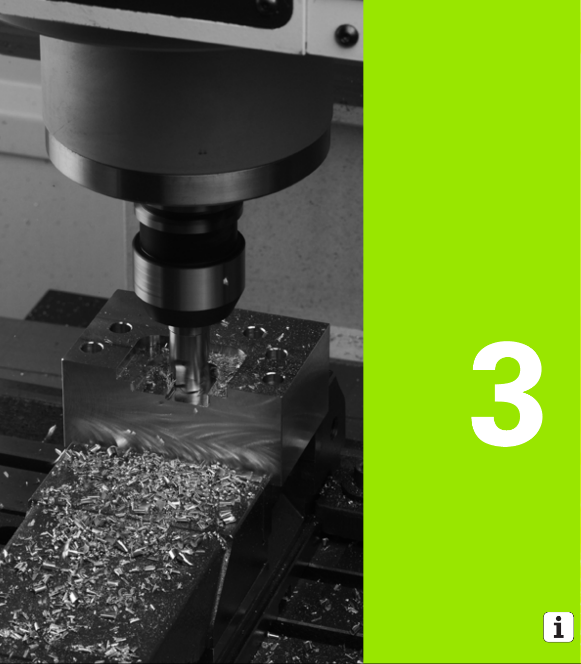
Programming: Fundamentals, File Management
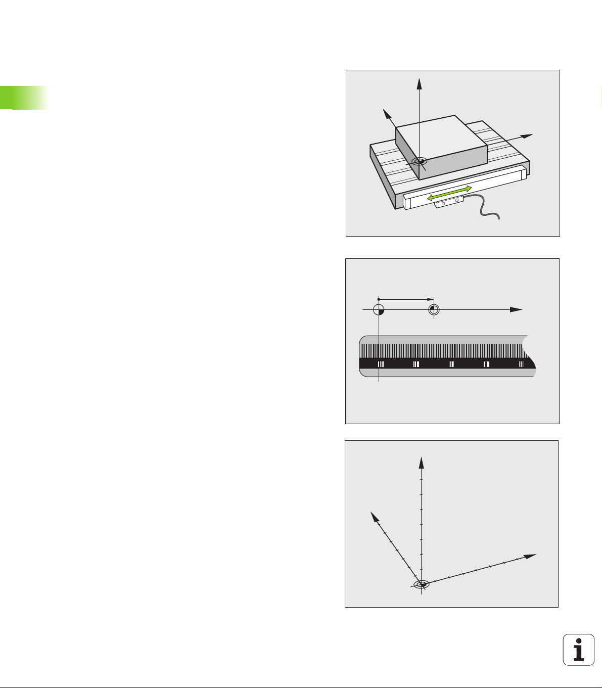
3.1 Fundamentals
Y
X
Z
X (Z,Y)
X
MP
Y
X
Z
Position encoders and reference marks
The machine axes are equipped with position encoders that register
the positions of the machine table or tool. Linear axes are usually
equipped with linear encoders, rotary tables and tilting axes with angle
encoders.
When a machine axis moves, the corresponding position encoder
generates an electrical signal. The TNC evaluates this signal and
calculates the precise actual position of the machine axis.
3.1 Fundamentals
If there is a power interruption, the calculated position will no longer
correspond to the actual position of the machine slide. To recover this
association, incremental position encoders are provided with
reference marks. The scales of the position encoders contain one or
more reference marks that transmit a signal to the TNC when they are
crossed over. From that signal the TNC can re-establish the
assignment of displayed positions to machine positions. For linear
encoders with distance-coded reference marks the machine axes
need to move by no more than 20 mm, for angle encoders by no more
than 20°.
With absolute encoders, an absolute position value is transmitted to
the control immediately upon switch-on. In this way the assignment
of the actual position to the machine slide position is re-established
directly after switch-on.
Reference system
A reference system is required to define positions in a plane or in
space. The position data are always referenced to a predetermined
point and are described through coordinates.
The Cartesian coordinate system (a rectangular coordinate system) is
based on the three coordinate axes X, Y and Z. The axes are mutually
perpendicular and intersect at one point called the datum. A
coordinate identifies the distance from the datum in one of these
directions. A position in a plane is thus described through two
coordinates, and a position in space through three coordinates.
Coordinates that are referenced to the datum are referred to as
absolute coordinates. Relative coordinates are referenced to any other
known position (reference point) you define within the coordinate
system. Relative coordinate values are also referred to as incremental
coordinate values.
98 Programming: Fundamentals, File Management
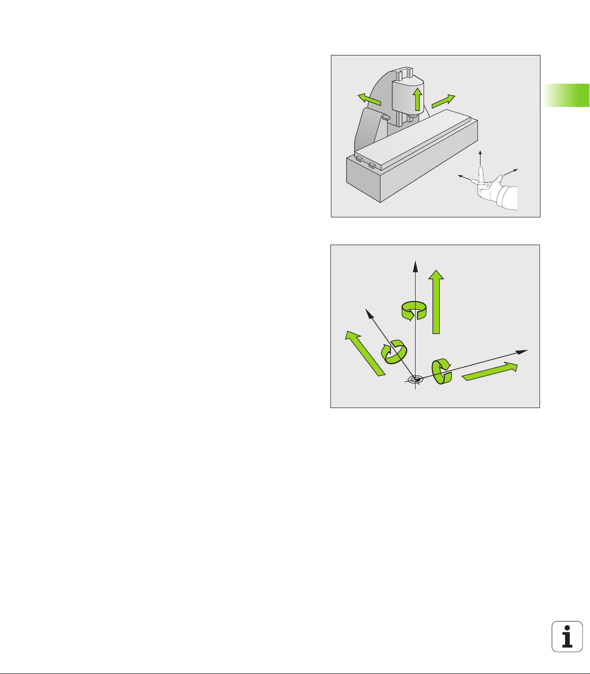
Reference system on milling machines
+X
+Y
+Z
+X
+Z
+Y
W+
C+
B+
V+
A+
U+
Y
X
Z
When using a milling machine, you orient tool movements to the
Cartesian coordinate system. The illustration at right shows how the
Cartesian coordinate system describes the machine axes. The figure
illustrates the right-hand rule for remembering the three axis
directions: the middle finger points in the positive direction of the tool
axis from the workpiece toward the tool (the Z axis), the thumb points
in the positive X direction, and the index finger in the positive Y
direction.
The iTNC 530 can control up to 18 axes. The axes U, V and W are
secondary linear axes parallel to the main axes X, Y and Z, respectively.
Rotary axes are designated as A, B and C. The illustration at lower right
shows the assignment of secondary axes and rotary axes to the main
axes.
In addition, the machine tool builder can define any number of auxiliary
axes identified by lowercase letters
3.1 Fundamentals
HEIDENHAIN iTNC 530 99
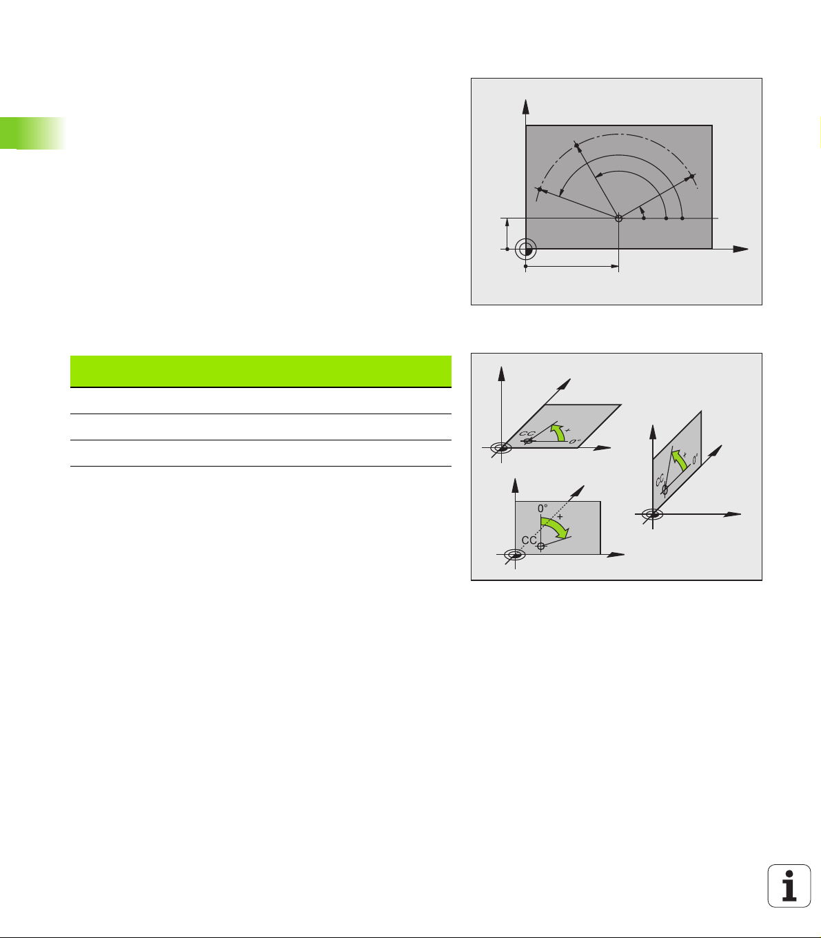
Polar coordinates
X
Y
0°
30
10
CC
PR
PA
1
PA
2
PR
PR
PA
3
X
Z
Y
X
Z
Y
X
Z
Y
If the production drawing is dimensioned in Cartesian coordinates, you
also write the NC program using Cartesian coordinates. For parts
containing circular arcs or angles it is often simpler to give the
dimensions in polar coordinates.
While the Cartesian coordinates X, Y and Z are three-dimensional and
can describe points in space, polar coordinates are two-dimensional
and describe points in a plane. Polar coordinates have their datum at a
circle center (CC), or pole. A position in a plane can be clearly defined
by the:
Polar Radius, the distance from the circle center CC to the position,
3.1 Fundamentals
and the
Polar Angle, the size of the angle between the reference axis and
the line that connects the circle center CC with the position
Setting the pole and the angle reference axis
The pole is set by entering two Cartesian coordinates in one of the
three planes. These coordinates also set the reference axis for the
polar angle PA.
Coordinates of the pole
(plane)
X/Y +X
Y/Z +Y
Z/X +Z
Reference axis of the angle
100 Programming: Fundamentals, File Management
 Loading...