

HEIDENHAIN Inverter Systems and Motors Technical Manual

Technical Manual
Inverter Systems
and
Motors
for the Contouring Controls
TNC 410 M
TNC 426 M
TNC 430 M
iTNC 530
MANUALplusM
MANUALplus 4110
CNC PILOT 4290
July 2002 208 962-21 · 3 · 7/2002 · S · Printed in Germany · Subject to change without notice
(208 962-E3)

Foreword
This Technical Manual has been written for all machine tool manufacturers. It
contains all of the information necessary for the mounting and electrical
installation of HEIDENHAIN inverter systems and HEIDENHAIN motors.
With each update, you will receive a set of supplementary pages free-ofcharge. Always sort these pages into your Technical Manual immediately. In
this way, your manual will always be up-to-date.
You can use extracts from this manual to supplement your machine
documentation. If you increase the size of the manual format (17 cm x 24 cm)
by the factor 1.225, you will have DIN A4 format.
No documentation can be perfect. To stay up to date, documentation must
change constantly. It also thrives on your comments and suggestions for
improvement. Please help us by sending us your ideas.
DR. JOHANNES HEIDENHAIN GmbH
E/P Department
Dr.-Johannes-Heidenhain-Str. 5
83301 Traunreut
July 2002 208 962-21 · 3 · 7/2002 · S · Printed in Germany · Subject to change without notice
(208 962-E3)

1 Update Information No. 3
1.1 General Information
n New SM 110 voltage protection module for use with synchronous spindle
motors
n Temperature sensor on the PW 1x0
n Double-row configuration of the HEIDENHAIN inverter system
1.2 Compact Inverters
n UE 241B no longer available
n New regenerative compact inverters
• UR 230: Continuous load on axes: 2 x 7.5 A
• UR 240: Continuous load on axes: 3 x 7.5 A
• UR 242: Continuous load on axes: 3 x 7.5 A; 1 x 25 A
n New connections for controlling the motor brakes: X344, X392 and X393
1.3 Modular Inverter
n New UV 150 regenerative power supply unit with KDR 150 commutation
reactor
UV 150: DC-link full-load power: 50 kW
n New UM 115 power module
n New variants of the UV 1xx power units
n Current consumptions from the 15-V and 24-V power supply of the inverter
system must be inspected
n New connections for controlling the motor brakes: X344 and X392
Continuous load on spindle: 25 A
Continuous load on spindle: 35 A
Continuous load on spindle: 35 A
1.4 Motors
n QSY 96, QSY 116, QSY 155 with EQN 1325 absolute multiturn rotary
encoder
n New QSY 155B synchronous motors with n
Designation Stall torque M
QSY 155B 13 Nm 2000 rpm
QSY 155C 17.7 Nm 3000 rpm
n Input values for the digital current controller
July 2002 Update Information No. 3 1 – 1
0
= 2000 rpm and QSY 155C
N
Rated speed n
N

1.5 Replacing Instructions
Page Change Remove
Page
Title New date of issue February 99 July 2002
Chapter 1 Update Information – Update
Chapter 2 n Printing errors corrected
n UE 241 B removed
n UR 2xx, UV 150, KDR 150 and UM 115 added
n Continuous load and short term rating for different
PWM frequencies
n Peak performances for 0.2 s
n Current consumption of the 15-V and 24-V supply
n Covers included in the items supplied with the
compact inverters
n Selection tables for ribbon cables and covers revised
n SM 110 voltage protection module added
n Double-row configuration of inverter systems
Chapter 3 n Performance overview of a drive system added Entire chapter Entire
Chapter 4 n Note on radio interferences
n Cross sections of the power cables
n HEIDENHAIN recommends use of the three-phase
current capacitor
n Note on leakage current
Chapter 5 n Printing errors corrected
n UE 241B removed
n UR 2xx added
n New connections for controlling the motor brakes:
X344, X392 and X393
n Line fuse for UE 2xx, UV 102, UE 2xxB
n Temperature switch on the PW 110B
n Additional voltage to X70, X71, X72
n Tightening torque of the electrical screw connections
added
n Dimensions only in mm
Chapter 6 n New connections for controlling the motor brakes:
X344 and X392
n Printing errors corrected
n Line fuse for UV 1x0
n Temperature switch on the PW 110B
n Additional voltage to X70, X71, X72
n Tightening torque of the electrical screw connections
added
n Dimensions only in mm
Entire chapter Entire
Entire chapter Entire
Entire chapter Entire
Entire chapter Entire
Insert
Page
Info. 3
chapter
chapter
chapter
chapter
chapter
1 – 2 HEIDENHAIN Technical Manual for Inverter Systems and Motors
Page Change Remove
Page
Chapter 7 n Printing errors corrected
Entire chapter Entire
n Bend radii of the power and encoder cables
Insert
Page
chapter
n Calculation of the maximum torque of a drive
n Pin layout for speed encoders with EnDat interface
n Note on differences between internal connections, ID
label and motor tables of QAN 30 and QAN 4S
n Power modules for QAN 3M: UM 111B, UM 121B
n Turning radius for connectors changed
n Incorrect assignment for the fan connection on QAN
104 and QSY 112D
n QSY 96, QSY 116, QSY 155 with EQN 1325 absolute
multiturn rotary encoder added
n QSY 155B (n
= 2000 rpm) and QSY 155C added
N
n Specifications for QSY 155B revised
n Characteristic curves revised
n Bearing service life for QSY 041B, QSY 071B,
QSY 090B, QSY 093B and QSY 112 series
n Bearing service life for QAN 104, QAN 134 and
QAN 164B
n Dimensions only in mm
n Input values for the digital current controller
Chapter 8 Keyword index Entire chapter Entire
chapter
July 2002 Update Information No. 3 1 – 3

1 – 4 HEIDENHAIN Technical Manual for Inverter Systems and Motors

2 Introduction
2.1 General Information ...........................................................................2–2
2.2 Designations of the Inverters and Motors........................................2–2
2.3 Compact Inverters ..............................................................................2–3
2.3.1 Components of the Compact Inverter ......................................... 2–3
2.3.2 UE 2xx compact inverter .............................................................2–4
2.3.3 UE 2xxB and UR 2xx Compact Inverters .....................................2–5
2.3.4 UV 102 power supply unit .........................................................2–12
2.3.5 Toroidal Cores ...........................................................................2–13
2.3.6 Ribbon Cables and Covers (Only for UE 2xxB, UR 2xx) ............ 2–13
2.4 Modular Inverter...............................................................................2–16
2.4.1 Components of the Modular Inverter ........................................ 2–16
2.4.2 UV 1x0 power supply unit .........................................................2–17
2.4.3 UM 1xx power modules ............................................................2–19
2.4.4 Current Consumption of the Entire Inverter System ................. 2–24
2.4.5 Ribbon cables and covers ..........................................................2–24
2.5 Accessories for Compact Inverters and Modular Inverters...........2–29
2.5.1 PW 210, PW 110(B), PW 120 Braking Resistor ........................2–29
2.5.2 KDR 1x0 commutating reactor and line filter ............................2–31
2.5.3 UP 110 braking resistor module ................................................2–33
2.5.4 SM 110 Voltage Protection Module .......................................... 2–34
2.5.5 Double-Row Configuration of HEIDENHAIN Components ........ 2 –35
July 2002 2 – 1
2 Introduction
2.1 General Information
This Technical Manual describes all of the inverter components and motors
that are necessary for a complete drive system. The drive systems can be
used in connection with the HEIDENHAIN TNC 4xx M contouring controls, as
well as the controls equipped with a CC 42x controller unit.
You will find the specifications for the controls in the corresponding Technical
Manuals.
2.2 Designations of the Inverters and Motors
Designation Device
UE 2xx Non-regenerative compact inverter for up to
4 axes and spindle (internal PWM interfaces)
UE 2xxB Non-regenerative compact inverter for up to
4 axes and spindle (external PWM interfaces),
an additional UM 111 power module can be
connected
UR 2xx Regenerative compact inverter for up to 4 axes
and spindle, an additional UM 111 power
module can be connected
UV 102 Power supply unit for operating the LE 426M
with the UE 2xx compact inverter (old)
PW 210 Braking resistor without fan
PW 110(B), PW 120 Braking resistor with fan
UV 130 Non-regenerative power module of the
modular inverter system
UV 120, UV 140, UV 150 Energy-recovery power modules of the
modular inverter system
KDR 120, KDR 140,
KDR 150
Line filters Line filters for the UV 120, UV 140 and UV 150
UP 110 UP 110 braking resistor module for the modular
UM 1xx (B) Power module for the modular inverter system
SM 110 Voltage protection module for synchronous
QSY Synchronous motor
QAN Asynchronous motor
Commutating reactors for the UV 120, UV 140
and UV 150 energy-recovery power modules
energy-recovery power modules
inverter system with regenerative power
supply.
for up to 2 axes or spindle
motors
2 – 2 HEIDENHAIN Technical Manual for Inverter Systems and Motors

2.3 Compact Inverters
For up to 4 axes and spindle, or up to 5 axes.
2.3.1 Components of the Compact Inverter
For operation with the non-regenerative HEIDENHAIN UE 2xx compact
inverters, you need the following components:
n UE 2xx compact inverter
n If required, PW 210 (or PW 110(B), PW 120) braking resistor
n Toroidal cores
n UV 102 power module (only LE 426 M)
For operation with the non-regenerative HEIDENHAIN UE 2xxB compact
inverters, you need the following components:
n UE 2xxB Compact inverter
n If required, PW 210 (or PW 110(B), PW 120) braking resistor
n Toroidal cores
n One UM 111 power module (optional)
n Ribbon cables for PWM signals and supply voltage (and optional unit bus)
n Covers for the ribbon cables
For operation with the regenerative HEIDENHAIN UR 2xx compact inverters,
you need the following components:
n UR 2xx compact inverter
n KDR 120 commutating reactor
n EPCOS 35 A line filter
n If required, UP 110 braking resistor module
n Toroidal cores
n One UM 111 power module (optional)
n Ribbon cables for PWM signals and supply voltage (and optional unit bus)
n Covers for the ribbon cables
July 2002 Compact Inverters 2 – 3
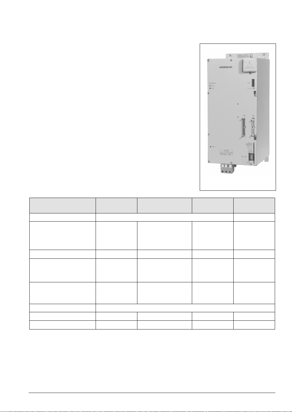
2.3.2 UE 2xx compact inverter
With UE 2xx compact inverters,
the power electronics for all of
the axes and the spindle, as well
as the power supply for the
control are all contained in a
single unit.
The PWM signals are
transferred via internal 20-pin
ribbon cables.
If you are using a LE 426 M, you
will require in addition the
UV 102 power supply unit.
UE 212
Specifications UE 210 UE 212 UE 230 UE 240 UE 242
Power supply 400 Vac ± 10 %
50 Hz to 60 Hz
Power consumption
Rated power
Peak power
Power loss Approx.
13 kW
18 kW
435 W
Approx.
555 W
20 kW
27.5 kW
Approx.
510 W
Approx.
580 W
Approx.
760 W
dc-link voltage 565 Vdc (at 400 V power supply)
Continuous load
Short-time load
a
Continuous power of the
3 axes
1 axis
spindle
3 axes
1 axis
spindle
7.5 A
–
19 A
15 A
–
28.5 A
7.5 A
14 A
19 A
15 A
28.5 A
28.5 A
2 x 7.5 A
–
31 A
2 x 15 A
–
46 A
7.5 A
–
31 A
15 A
–
46 A
1 kW – – –
7.5 A
23 A
31 A
15 A
46 A
46 A
integral braking resistor
Peak power of the integral
braking resistor
b
23 kW – – –
Degree of protection IP 20
Weight 20 kg 23 kg
ID number 313 500-xx 313 501-xx 329 037-xx 313 502-xx 313 503-xx
a. 40 % cyclic duration factor for duration of 10 minutes (S6-40 %) or for 0.2 s at standstill
b. 0.4 % cyclic duration factor for duration of 120 s
2 – 4 HEIDENHAIN Technical Manual for Inverter Systems and Motors
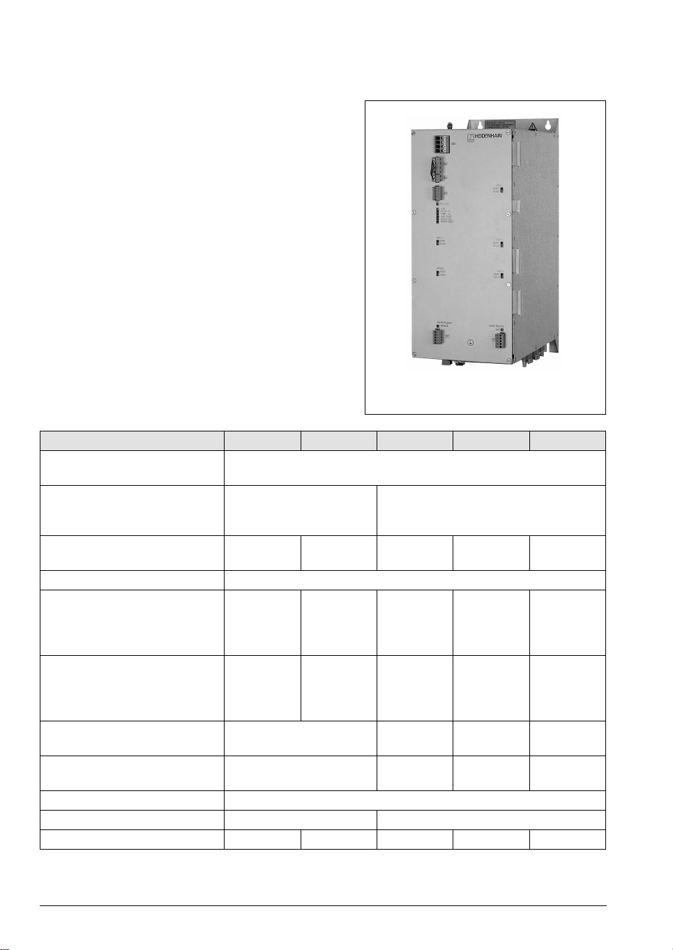
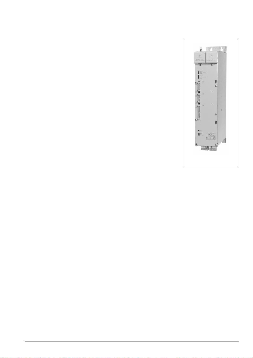
2.3.3 UE 2xxB and UR 2xx Compact Inverters
With UE 2xxB and UR 2xx
compact inverters, the power
electronics for all of the axes
and the spindle, as well as the
power supply for the control are
all contained in a single unit. An
additional UM 111 power
module of the modular inverter
system can be connected via
conductor bar.
There are regenerative (UR 2xx)
and non-regenerative (UE 2xxB)
compact inverters.
The PWM signals are
transferred via external 20 pin
ribbon cables.
UE 242 B
July 2002 Compact Inverters 2 – 5
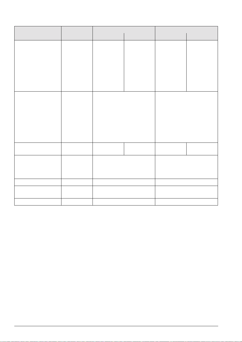
Specifications UE 210B
(non-regenerative)
UE 211B
(non-regenerative)
3 axes Spindle/Axis 2 axes 1 axis Spindle/Axis
Power supply 400 Vac ±10 % (50 Hz to 60 Hz)
dc-link voltage 565 Vdc (at 400 V power supply)
DC-link power
Rated power
Peak power
Peak power
a
b
15 kW
23 kW
40 kW
15 kW
23 kW
40 kW
Power loss Approx. 475 W Approx. 525 W
Continuous load at a PWM
frequency of 3333 Hz
4000 Hz
5000 Hz
6666 Hz
8000 Hz
10000 Hz
c
Short-time load
at a PWM
9.0 A
8.3 A
7.5 A
6.4 A
5.3 A
4.5 A
24.5 A/18.4 A
22.5 A/16.9 A
20.0 A/15.0 A
17.0 A/12.8 A
14.5 A/10.9 A
12.0 A/9.0 A
9.0 A
8.3 A
7.5 A
6.4 A
5.3 A
4.5 A
18.4 A
16.9 A
15.0 A
12.8 A
10.9 A
9.0 A
24.5 A/18.4 A
22.5 A/16.9 A
20.0 A/15.0 A
17.0 A/12.8 A
14.5 A/10.9 A
12.0 A/9.0 A
frequency of
3333 Hz
4000 Hz
5000 Hz
6666 Hz
8000 Hz
10000 Hz
Continuous power of the
15.0 A
15.0 A
15.0 A
12.8 A
10.6 A
9.0 A
30.0 A
30.0 A
30.0 A
25.5 A
21.8 A
18.0 A
15.0 A
15.0 A
15.0 A
12.8 A
10.6 A
9.0 A
1 kW 1 kW
30.0 A
30.0 A
30.0 A
25.6 A
21.8 A
18.0 A
30.0 A
30.0 A
30.0 A
25.5 A
21.8 A
18.0 A
integral braking resistor
Peak power of the integral
braking resistor
d
23 kW 23 kW
Degree of protection IP 20 IP 20
Weight Approx. 20 kg Approx. 20 kg
ID number 337 042-xx 337 043-xx
a. 40% cyclic duration factor for duration of 10 minutes (S6-40%)
b. 0.2 s cyclic duration factor for duration of 5 s
c. 40 % cyclic duration factor for duration of 10 minutes (S6-40 %) or for 0.2 s at standstill
d. 0.4 % cyclic duration factor for duration of 120 s
2 – 6 HEIDENHAIN Technical Manual for Inverter Systems and Motors

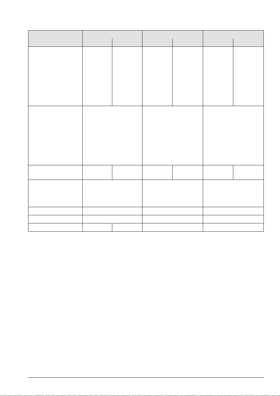
Specifications UE 212B
(non-regenerative)
UE 230B
(non-regenerative)
3 axes 1 axis Spindle/Axis 2 axes Spindle/Axis
Power supply 400 Vac ±10 % (50 Hz to 60 Hz)
dc-link voltage 565 Vdc (at 400 V power supply)
DC-link power
Rated power
Peak power
Peak power
a
b
15 kW
23 kW
40 kW
22 kW
30 kW
45 kW
Power loss Approx. 595 W Approx. 520 W
Continuous load at a PWM
frequency of 3333 Hz
4000 Hz
5000 Hz
6666 Hz
8000 Hz
10000 Hz
c
Short-time load
at a PWM
9.0 A
8.3 A
7.5 A
6.4 A
5.3 A
4.5 A
18.4 A
16.9 A
15.0 A
12.8 A
10.9 A
9.0 A
24.5 A/18.4 A
22.5 A/16.9 A
20.0 A/15.0 A
17.0 A/12.8 A
14.5 A/10.9 A
12.0 A/9.0 A
9.0 A
8.3 A
7.5 A
6.4 A
5.3 A
4.5 A
38.0 A/28.2 A
35.0 A/26.0 A
31.0 A/23.0 A
26.0 A/19.3 A
22.5 A/16.7 A
19.0 A/14.1 A
frequency of
3333 Hz
4000 Hz
5000 Hz
6666 Hz
8000 Hz
10000 Hz
15.0 A
15.0 A
15.0 A
12.8 A
10.6 A
9.0 A
30.0 A
30.0 A
30.0 A
25.6 A
21.8 A
18.0 A
30.0 A
30.0 A
30.0 A
25.5 A
21.8 A
18.0 A
15.0 A
15.0 A
15.0 A
12.8 A
10.6 A
9.0 A
46.0 A
46.0 A
46.0 A
38.6 A
33.4 A
28.2 A
Degree of protection IP 20 IP 20
Weight Approx. 23 kg Approx. 23 kg
ID number 337 044-xx 337 038-xx
a. 40% cyclic duration factor for duration of 10 minutes (S6-40%)
b. 0.2 s cyclic duration factor for duration of 5 s
c. 40 % cyclic duration factor for duration of 10 minutes (S6-40 %) or for 0.2 s at standstill
July 2002 Compact Inverters 2 – 7
Specifications UE 240B
(non-regenerative)
UE 242B
(non-regenerative)
2 axes Spindle/Axis 3 axes 1 axis Spindle/Axis
Power supply 400 Vac ±10 % (50 Hz to 60 Hz)
dc-link voltage 565 Vdc (at 400 V power supply)
DC-link power
Rated power
Peak power
Peak power
a
b
22 kW
30 kW
45 kW
22 kW
30 kW
45 kW
Power loss Approx. 520 W Approx. 770 W
Continuous load at a PWM
frequency of 3333 Hz
4000 Hz
5000 Hz
6666 Hz
8000 Hz
10000 Hz
c
Short-time load
at a PWM
9.0 A
8.3 A
7.5 A
6.4 A
5.3 A
4.5 A
38.0 A/28.2 A
35.0 A/26.0 A
31.0 A/23.0 A
26.0 A/19.3 A
22.5 A/16.7 A
19.0 A/14.1 A
9.0 A
8.3 A
7.5 A
6.4 A
5.3 A
4.5 A
28.2 A
26.0 A
23.0 A
19.3 A
16.7 A
14.1 A
38.0 A/28.2 A
35.0 A/26.0 A
31.0 A/23.0 A
26.0 A/19.3 A
22.5 A/16.7 A
19.0 A/14.1 A
frequency of
3333 Hz
4000 Hz
5000 Hz
6666 Hz
8000 Hz
10000 Hz
15.0 A
15.0 A
15.0 A
12.8 A
10.6 A
9.0 A
46.0 A
46.0 A
46.0 A
38.6 A
33.4 A
28.2 A
15.0 A
15.0 A
15.0 A
12.8 A
10.6 A
9.0 A
46.0 A
46.0 A
46.0 A
38.6 A
33.4 A
28.2 A
46.0 A
46.0 A
46.0 A
38.6 A
33.4 A
28.2 A
Degree of protection IP 20 IP 20
Weight Approx. 23 kg Approx. 23 kg
ID number 337 039-xx 337 041-xx
a. 40% cyclic duration factor for duration of 10 minutes (S6-40%)
b. 0.2 s cyclic duration factor for duration of 5 s
c. 40 % cyclic duration factor for duration of 10 minutes (S6-40 %) or for 0.2 s at standstill
2 – 8 HEIDENHAIN Technical Manual for Inverter Systems and Motors

Specifications UR 230
(regenerative)
2 axes Spindle/Axis
Power supply 400 Vac ±10 % (50 Hz to 60 Hz)
dc-link voltage 650 Vdc
DC-link power
Rated power
Peak power
Peak power
a
b
22 kW
30 kW
40 kW
Power loss Approx. 680 W
Continuous load at a PWM
frequency of 3333 Hz
4000 Hz
5000 Hz
6666 Hz
8000 Hz
10000 Hz
c
Short-time load
at a PWM
9.0 A
8.3 A
7.5 A
6.4 A
5.3 A
4.5 A
30.5 A
28.5 A
25.0 A
21.0 A
18.0 A
15.5 A
frequency of
3333 Hz
4000 Hz
5000 Hz
6666 Hz
8000 Hz
10000 Hz
15.0 A
15.0 A
15.0 A
12.8 A
10.6 A
9.0 A
50.0 A
50.0 A
50.0 A
42.0 A
36.0 A
31.0 A
Degree of protection IP 20
Weight Approx. 22.5 kg
ID number 362 593-xx
a. 40% cyclic duration factor for duration of 10 minutes (S6-40%)
b. 0.2 s cyclic duration factor for duration of 5 s
c. 40 % cyclic duration factor f or duration of 10 minut es (S6-40 %) or
for 0.2 s at standstill
July 2002 Compact Inverters 2 – 9
Specifications UR 240
(regenerative)
3 axes Spindle/Axis 3 axes 1 Axis/
UR 242
(regenerative)
Spindle/Axis
Spindle
Power supply 400 Vac ±10 % (50 Hz to 60 Hz)
dc-link voltage 650 Vdc
DC-link power
Rated power
Peak power
Peak power
a
b
22 kW
30 kW
40 kW
22 kW
30 kW
40 kW
Power loss Approx. 750 W Approx. 930 W
Continuous load at a PWM
frequency of 3333 Hz
4000 Hz
5000 Hz
6666 Hz
8000 Hz
10000 Hz
c
Short-time load
at a PWM
9.0 A
8.3 A
7.5 A
6.4 A
5.3 A
4.5 A
42.5 A/30.4 A
39.5 A/28.3 A
35.0 A/25.0 A
29.5 A/21.1 A
25.0 A/17.9 A
21.5 A/15.4 A
9.0 A
8.3 A
7.5 A
6.4 A
5.3 A
4.5 A
30.5 A
28.5 A
25.0 A
21.0 A
18.0 A
15.5 A
42.5 A/30.4 A
39.5 A/28.3 A
35.0 A/25.0 A
29.5 A/21.1 A
25.0 A/17.9 A
21.5 A/15.4 A
frequency of
3333 Hz
4000 Hz
5000 Hz
6666 Hz
8000 Hz
10000 Hz
15.0 A
15.0 A
15.0 A
12.8 A
10.6 A
9.0 A
50.0 A
50.0 A
50.0 A
42.1 A
35.7 A
30.7 A
15.0 A
15.0 A
15.0 A
12.8 A
10.6 A
9.0 A
50.0 A
50.0 A
50.0 A
42.0 A
36.0 A
31.0 A
50.0 A
50.0 A
50.0 A
42.1 A
35.7 A
30.7 A
Degree of protection IP 20 IP 20
Weight Approx. 22.5 kg Approx. 22.5 kg
ID number 367 558-xx 367 559-xx
a. 40% cyclic duration factor for duration of 10 minutes (S6-40%)
b. 0.2 s cyclic duration factor for duration of 5 s
c. 40 % cyclic duration factor for duration of 10 minutes (S6-40 %) or for 0.2 s at standstill
2 – 10 HEIDENHAIN Technical Manual for Inverter Systems and Motors

Changes to the UE 2xxB
337 xxx-02 First issue UE 2xxB
337 xxx-03 Only UE 230B and UE 24xB:
New connections for motor brakes and
sliding switches
Changes to UR 230
362 593-02 Initial version
Changes to UR 24x
367 55x-02 First issue UR 24x
July 2002 Compact Inverters 2 – 11
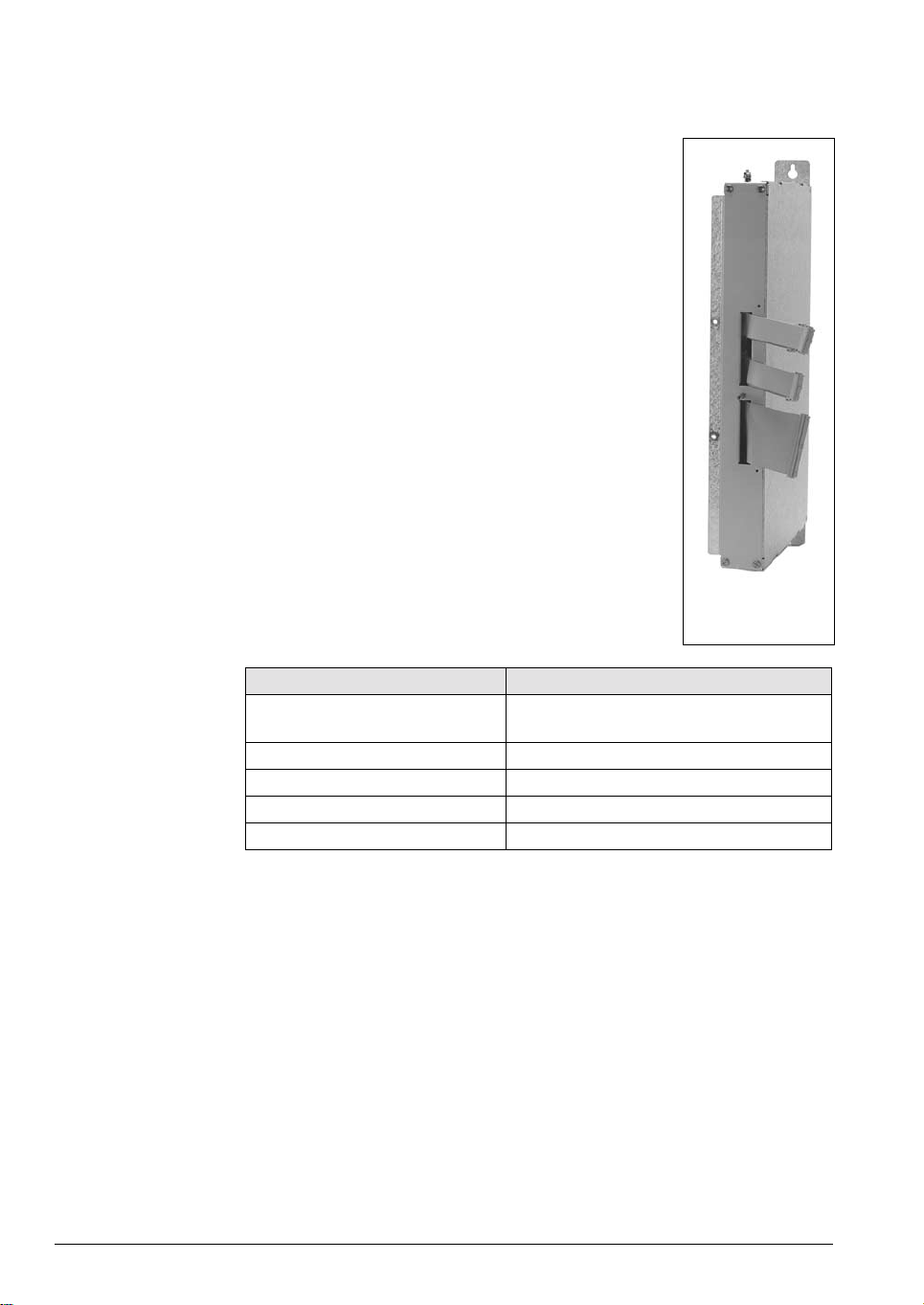
2.3.4 UV 102 power supply unit
The UV 102 power supply unit is necessary if you are
using a UE 2xx (not UE 2xxB) compact inverter with an
LE 426 M. It supplies the power to the LE 426 M and
leads the external PWM connections of the logic unit to
the UE 2xx compact inverter.
UV 102
Specifications UV 102
Power supply 400 Vac ± 10 %
50 Hz to 60 Hz
Power consumption Approx. 100 W
Degree of protection IP 20
Weight 3 kg
ID number 317 559-02
2 – 12 HEIDENHAIN Technical Manual for Inverter Systems and Motors

2.3.5 Toroidal Cores
To suppress occurrence of interference, toroidal cores must be mounted in
the motor leads, in the voltage supply lead and in the lead to the braking
resistor (only UE 21x).
Terminal on the compact inverter Toroidal core
Power supply (X31) ∅ 87 mm (309 694-02)
Braking resistor (X89)
a
Axes 1 to 3 (X81 to X83) ∅ 42 mm (309 694-01)
Axis 4 (X84) ∅ 59 mm (309 694-03)
Spindle (X80) ∅ 59 mm (309 694-03)
a. only for UE 21x
2.3.6 Ribbon Cables and Covers (Only for UE 2xxB, UR 2xx)
∅ 42 mm (309 694-01)
50-line ribbon cable
(power supply to
the control)
20-line ribbon cable
(PWM signals)
40-line ribbon cable
(unit bus)
The 50-line ribbon cable connects the UE 2xxB or UR 2xx to the control and is
responsible for the power supply. It is available as an accessory with the
compact inverter (length 300 mm, Id. Nr. 325 816-01).
The 20-line ribbon cable connects the PWM outputs of the control with the
PWM connections on the compact inverter. One 20-line ribbon cable is
required for each axis/spindle. The 20-line ribbon cables for the connections on
the compact inverter are supplied as accessories with the UE 2xxB (length
200 mm, Id. Nr. 250 479-08; length 400 mm, Id. Nr. 250 479-10). If you are
using an additional UM 111 power module, you will need an additional 20-line
ribbon cable:
PWM connection on the
UM 111 power module
Length of the 20-line
ribbon cable
ID number
X111, X112 100 mm 250 479-07
The 40-line ribbon cable serves as the unit bus. It is required if an additional
UM 111 power module is being operated with the compact inverter.
Unit bus connection Length of the 40-line
ID number
ribbon cable
X79 50 mm 325 817-09
July 2002 Compact Inverters 2 – 13

Ribbon cable covers The ribbon cables must be covered to protect them against interference.
The covers for the LE 4xx M and CC 42x are supplied with the LE 4xx M and
CC 42x, respectively.
The cover for the compact inverter is included in the standard set (197.5 mm,
Id. Nr. 325 808-07).
The plastic lateral termination cap has the Id. Nr. 325 810-01.
If you are using an additional power module, the cover for this module must
be ordered separately:
Additional power module Length of
the cover
UM 111 50 mm 329 031-05
ID number
2 – 14 HEIDENHAIN Technical Manual for Inverter Systems and Motors

✎
July 2002 Compact Inverters 2 – 15

2.4 Modular Inverter
2.4.1 Components of the Modular Inverter
For operation with the modular HEIDENHAIN non-regenerative inverters, the
following components are required:
n UV 130 Power Supply Unit
n UM 1xx power modules, depending on version
n PW 210 (or PW 110(B), PW 120) braking resistor
n Ribbon cables for PWM signals, unit bus and power supply
n Covers for the ribbon cables
For operation with the modular HEIDENHAIN regenerative inverters, the
following components are required:
n UV 120, UV 140 or UV 150 power supply unit
n KDR 120, KDR 140 or KDR 150 commutating reactor
n Line filters
n If required, UP 110 braking resistor module
n UM 1xx (B) power modules, depending on version
n Ribbon cables for PWM signals, unit bus and power supply
n Covers for the ribbon cables
2 – 16 HEIDENHAIN Technical Manual for Inverter Systems and Motors
2.4.2 UV 1x0 power supply unit
The UV 1x0 power supply units supply the
dc-link voltage as well as the power for the
electronics of the control and power
modules.
During braking, the motors feed energy into
the dc-link. This energy is converted into
heat by the UV 130 through the PW 210 or
PW 1x0(B) braking resistor, or returned to
the power line through the UV 120 or
UV 140.
The UV 120 and UV 140 can be driven only
with commutating reactor and line filter.
UV 140
Specifications UV 120
(regenerative)
UV 130
(non-regenerative)
UV 140
(regenerative)
UV 150
(regenerative)
Power supply 400 Vac ±10 % (50 Hz to 60 Hz)
DC-link power
Rated power
Peak power
Peak powerb
a
22 kW
30 kW
40 kW
30 kW
40 kW
50 kW
45 kW
65 kW
80 kW
50 kW
75 kW
110 kW
Power loss Approx. 300 W Approx. 140 W Approx. 570 W Approx. 640 W
dc-link voltage 650 Vdc 565 Vdc 650 Vdc 650 Vdc
(with 400 V power
voltage)
Current consumption
15 V
24 V
c
270 mA/
310 mA
240 mA
410 mA
380 mA
310 mA
350 mA
540 mA
Degree of protection IP 20
Weight Approx. 12.0 kg Approx. 9.8 kg Approx. 20.0 kg Approx. 20.0 kg
ID number 344 504-xx 324 998-xx 335 009-xx 361 170-xx
a. 40% cyclic duration factor for duration of 10 minutes (S6-40%)
b. 0.2 s cyclic duration factor for duration of 5 s
c. After making your selection, check the current consumption of the 25-V and 24-V supply of
the entire modular inverter system. See page 2 - 24.
July 2002 Modular Inverter 2 – 17

Changes to UV 120
344 504-01 Initial version
344 504-02 Power supply revised (grounding safety)
Changes to UV 130
324 998-01 Initial version
324 998-02 Modification
324 998-03 Modification
Changes to UV 140
335 009-01 Initial version
335 009-02 Modification
335 009-03 Power supply revised (grounding safety)
Changes to UV 150
361 170-02 Initial version
2 – 18 HEIDENHAIN Technical Manual for Inverter Systems and Motors
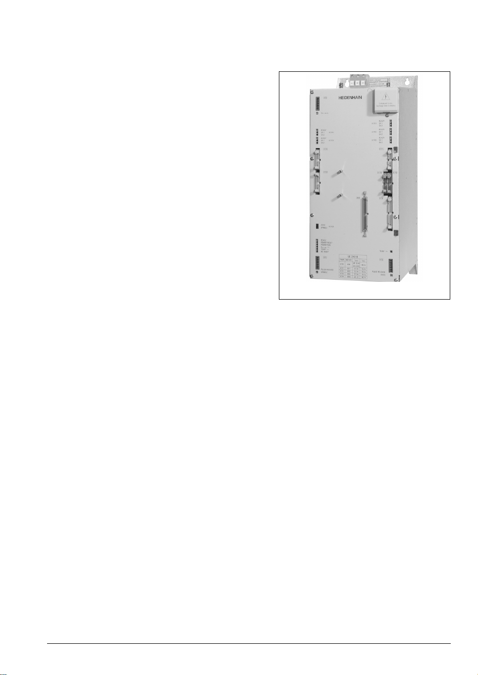
2.4.3 UM 1xx power modules
The power modules differ in the number of axes
and the permissible maximum currents. They can
be combined at random. The PWM signals are
transferred from the control via external 20-line
ribbon cables.
UM 121B
July 2002 Modular Inverter 2 – 19
Specifications UM 111 UM 111B UM 112
Axis Axis Spindle Axis Spindle
Continuous load at a
PWM frequency of
3333 Hz
4000 Hz
5000 Hz
6666 Hz
8000 Hz
10000 Hz
Short-time load
a
at a
9.0 A
8.3 A
7.5 A
6.4 A
5.3 A
4.5 A
18.4 A
16.9 A
15.0 A
12.8 A
10.9 A
9.0 A
24.5 A
22.5 A
20.0 A
17.0 A
14.5 A
12.0 A
28.2 A
26.0 A
23.0 A
19.3 A
16.7 A
14.1 A
38.0 A
35.0 A
31.0 A
26.0 A
22.5 A
19.0 A
PWM frequency of
3333 Hz
4000 Hz
5000 Hz
6666 Hz
8000 Hz
10000 Hz
Power loss Approx. 70 W Approx.
Current
consumption
b
15 V
15.0 A
15.0 A
15.0 A
12.8 A
10.6 A
9.0 A
120 mA
60 mA
30.0 A
30.0 A
30.0 A
25.6 A
21.8 A
18.0 A
120 W
150 mA
170 mA
Approx.
160 W
46.0 A
46.0 A
46.0 A
38.6 A
33.4 A
28.2 A
Approx.
180 W
170 mA
170 mA
Approx.
270 W
24 V
Degree of protection IP 20 IP 20 IP 20
Weight Approx.
Approx. 5.5 kg Approx. 9 kg
5.5 kg
ID number 325 000-xx 336 948-xx 325 001-xx
a. 40 % cyclic duration factor for duration of 10 minutes (S6-40 %) or for 0.2 s at standstill
b. After making your selection, check the current consumption of the 25-V and 24-V supply of
the entire modular inverter system. See page 2 - 24.
2 – 20 HEIDENHAIN Technical Manual for Inverter Systems and Motors
Specifications UM 113 UM 114 UM 115
Axis Spindle Axis Spindle Axis Spindle
Continuous load at a
PWM frequency of
3333 Hz
4000 Hz
5000 Hz
6666 Hz
8000 Hz
10000 Hz
Short-time load
a
at a
39.0 A
36.2 A
32.0 A
26.9 A
23.0 A
19.5 A
61.0 A
56.5 A
50.0 A
42.0 A
36.0 A
30.5 A
58.6 A
54.4 A
48.0 A
40.3 A
34.6 A
29.4 A
91.5 A
85.0 A
75.0 A
63.0 A
54.0 A
46.0 A
85.4 A
79.1 A
70.0 A
58.5 A
50.4 A
42.7 A
122.0 A
113.0 A
100.0 A
84.0 A
72.0 A
61.0 A
PWM frequency of
3333 Hz
4000 Hz
5000 Hz
6666 Hz
8000 Hz
10000 Hz
Power loss Approx.
Current
consumption
b
15 V
64.0 A
64.0 A
64.0 A
53.8 A
46.0 A
39.0 A
280 W
170 mA
250 mA
Approx.
430 W
96.0 A
96.0 A
96.0 A
80.6 A
69.2 A
58.8 A
Approx.
420 W
250 mA
420 mA
Approx.
650 W
140.0 A
140.0 A
140.0 A
117.6 A
100.8 A
85.4 A
Approx.
610 W
270 mA
420 mA
Approx.
870 W
24 V
Degree of protection IP 20 IP 20 IP 20
Weight Approx. 9.0 kg Approx. 12.0 kg Approx. 19.0 kg
ID number 325 002-xx 325 005-xx 359 385-xx
a. 40 % cyclic duration factor for duration of 10 minutes (S6-40 %) or for 0.2 s at standstill
b. After making your selection, check the current consumption of the 25-V and 24-V supply of
the entire modular inverter system. See page 2 - 24.
July 2002 Modular Inverter 2 – 21

Specifications UM 121 UM 121B
a
UM 122
a
Axes Axis Spindle Axis Spindle
Continuous load at a
PWM frequency of
3333 Hz
4000 Hz
5000 Hz
6666 Hz
8000 Hz
10000 Hz
Short-time load
b
at a
9.0 A
8.3 A
7.5 A
6.4 A
5.3 A
4.5 A
18.4 A
16.9 A
15.0 A
12.8 A
10.9 A
9.0 A
24.5 A
22.5 A
20.0 A
17.0 A
14.5 A
12.0 A
28.2 A
26.0 A
23.0 A
19.3 A
16.7 A
14.1 A
38.0 A
35.0 A
31.0 A
26.0 A
22.5 A
19.0 A
PWM frequency of
3333 Hz
4000 Hz
5000 Hz
6666 Hz
8000 Hz
10000 Hz
Power loss Approx. 140 W 2 axes: Approx. 240 W
Current consumption
15 V
24 V
15.0 A
15.0 A
15.0 A
12.8 A
10.6 A
9.0 A
c
120 mA
60 mA
30.0 A
30.0 A
30.0 A
25.6 A
21.8 A
18.0 A
1 axis, 1 spindle:
Approx. 280 W
150 mA
170 mA
46.0 A
46.0 A
46.0 A
38.6 A
33.4 A
28.2 A
2 axes: Approx. 360 W
1 axis, 1 spindle:
Approx. 450 W
170 mA
170 mA
Degree of protection IP 20 IP 20 IP 20
Weight Approx. 5.5 kg Approx. 5.5 kg Approx. 9.0 kg
ID number 325 000-xx 336 948-xx 325 001-xx
a. for this power module only the lower PWM connection can be used to control the spindle
b. 40 % cyclic duration factor for duration of 10 minutes (S6-40 %) or for 0.2 s at standstill
c. After making your selection, check the current consumption of the 25-V and 24-V supply of
the entire modular inverter system. See page 2 - 24.
2 – 22 HEIDENHAIN Technical Manual for Inverter Systems and Motors

Changes to UM 1x1
xxx xxx-01 Initial version
xxx xxx-02 New connections for motor brakes
Changes to UM 1x1B
xxx xxx-02 Initial version
xxx xxx-03 New connections for motor brakes
Changes to UM 1x2
xxx xxx-01 Initial version
xxx xxx-02 New connections for motor brakes
Changes to UM 113 and UM 114
xxx xxx-01 Initial version
xxx xxx-02 New connections for motor brakes
Changes to UM 115
359 385-01 Initial version
July 2002 Modular Inverter 2 – 23
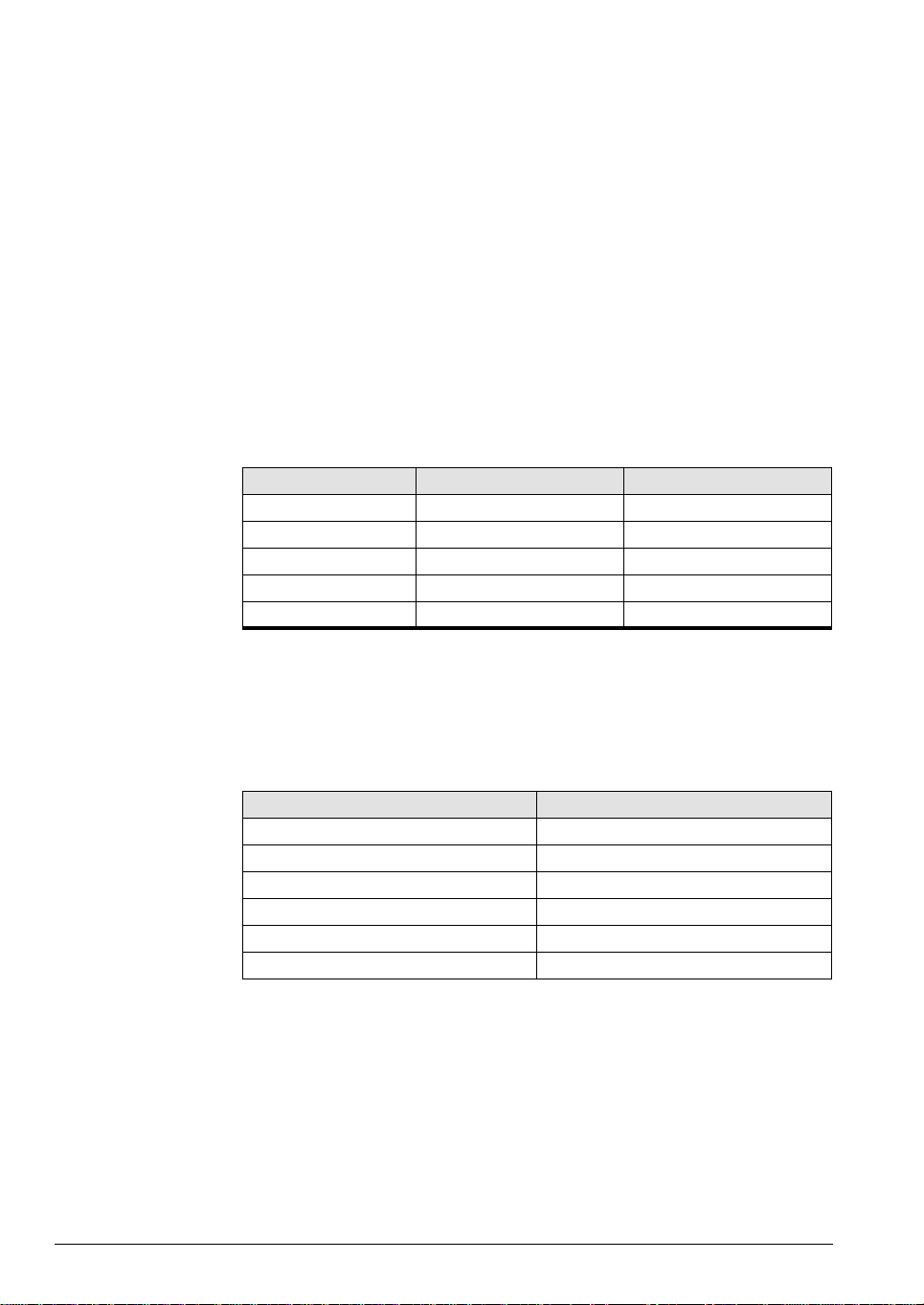
2.4.4 Current Consumption of the Entire Inverter System
The current consumption by the power modules from the 15-V and 24-V
supply unit strongly depends on their performance. If several highperformance power modules are used, the maximum permissible current for
the supply unit can be exceeded. Therefore the current consumption must be
controlled separately for the 15-V and 24-V supply units, especially when the
UV 150 is used with a UM 115. The intrinsic needs of the supply unit must also
be taken into account. The current consumption of the individual components
is listed in the specifications table.
The following limit values apply:
n 15-V supply unit: Max. 1.5 A
n 24-V supply unit: Max. 2.0 A
If the total current consumption exceeds one limit value, please contact
HEIDENHAIN.
Example:
Device 15 V power supply 24 V power supply
UV 140 0.38 A 0.31 A
UM 114 0.25 A 0.42 A
UM 121B 0.25 A 0.17 A
UM 121 0.20 A 0.21 A
UM 111 0.12 A 0.06 A
Total 1.20 A 1.17 A
2.4.5 Ribbon cables and covers
50-line ribbon cable
(power supply to
The 50-line ribbon cable connects the UV 1x0 with the control and serve as
voltage supply. This cable is only required once.
the control)
Ribbon cable length ID number
300 mm 325 816-01
400 mm 325 816-02
500 mm 325 816-03
600 mm
700 mm
800 mm
a. With lengths of 600 mm and longer, the ribbon cable is led
How to select the cable length:
U
U Add the widths of all module s (including UP 110) between
UU
• UV 1x0 and LE 4xx M or CC 42x
• UV 1x0 and UV 105
U
U Select the next-longer cable length, unless there is an exact match.
UU
a
a
a
325 816-04
325 816-05
325 816-06
doubled to increase the line cross section.
2 – 24 HEIDENHAIN Technical Manual for Inverter Systems and Motors
 Loading...