


 Loading...
GV-Video Server
User's Manual
Before attempting to connect or operate this product,
please read these instructions carefully and save this manual for future use.
VS-UM-A

© 2018 GeoVision, Inc. All rights reserved.
Under the copyright laws, this manual may not be copied, in whole or in part, without the written consent of GeoVision.
Every effort has been made to ensure that the information in this manual is accurate. GeoVision, Inc. makes no expressed or implied warranty of any kind and assumes no responsibility for errors or omissions. No liability is assumed for incidental or consequential damages arising from the use of the information or products contained herein. Features and specifications are subject to change without notice.
Note: No memory card slot or local storage function for Argentina.
GeoVision, Inc.
9F, No. 246, Sec. 1, Neihu Rd., Neihu District, Taipei, Taiwan Tel: +886-2-8797-8377
Fax: +886-2-8797-8335 http://www.geovision.com.tw
Trademarks used in this manual: GeoVision, the GeoVision logo and GV series products are trademarks of GeoVision, Inc. Windows is the registered trademarks of Microsoft Corporation.
February, 2018

Preface
Welcome to the GV-Video Server User’s Manual.
GV-Video Server has a series of models designed to meet different needs. Each model has its own firmware that can only be used on the specific model. This Manual is designed for the following models and firmware version:
Model |
Firmware Version |
|
|
GV-VS04H |
1.08 |
|
|
GV-VS11 |
1.05 |
|
|
GV-VS12 |
1.09 |
|
|
GV-VS14 |
1.03 |
|
|
GV-VS2400 |
1.07 |
|
|
GV-VS2401 |
1.00 |
|
|
GV-VS2420 |
1.07 |
|
|
GV-VS2800 |
1.03 |
|
|
GV-VS2820 |
1.03 |
|
|
GV-VS21600 |
1.00 |
|
|
IMPORTANT: For better recording efficiency and stability of GV-Video Server, after upgrading the firmware to the above version, it is required to format the storage device. To format the storage device, be sure to back up the data first and see 4.8.3 Storage Settings for how to format the storage device.
i
Caution
GV-Video Server is designed only for indoor usage.
ii
|
|
Contents |
|
Chapter 1 |
Introduction .......................................................... |
1 |
|
1.1 |
Models and Features ............................................................................................. |
1 |
|
1.2 |
Packing List ........................................................................................................... |
3 |
|
|
1.2.1 |
GV-VS04H / 14.......................................................................................... |
3 |
|
1.2.2 |
GV-VS11 ................................................................................................... |
3 |
|
1.2.3 |
GV-VS12 ................................................................................................... |
4 |
|
1.2.4 |
GV-VS2420 / 2400..................................................................................... |
4 |
|
1.2.5 |
GV-VS2401 ............................................................................................... |
5 |
|
1.2.6 |
GV-VS2820 / 2800..................................................................................... |
5 |
|
1.2.7 |
GV-VS21600 ............................................................................................. |
6 |
1.3 |
Compatible Products and System Requirements ................................................... |
7 |
|
|
1.3.1 |
Compatible GeoVision Software ................................................................ |
7 |
|
1.3.2 |
System Requirements................................................................................ |
8 |
1.4 |
PoE Support .......................................................................................................... |
8 |
|
1.5 |
GPS Support.......................................................................................................... |
9 |
|
1.6 |
Options ................................................................................................................. |
10 |
|
1.7 |
Physical Description.............................................................................................. |
13 |
|
|
1.7.1 |
Front View ................................................................................................ |
13 |
|
1.7.2 |
Rear View................................................................................................. |
20 |
Chapter 2 |
Getting Started ................................................... |
25 |
|
2.1 |
Installing on a Network.......................................................................................... |
25 |
|
2.2 |
Checking the IP Address ...................................................................................... |
27 |
|
2.3 |
Changing the IP Address ...................................................................................... |
28 |
|
2.4 |
Configuring the Basics .......................................................................................... |
29 |
|
Chapter 3 Accessing the GV-Video Server ....................... |
30 |
||
3.1 |
Accessing Your Surveillance Images .................................................................... |
30 |
|
3.2 |
Functions Featured on the Main Page .................................................................. |
32 |
|
|
3.2.1 |
The Live View Window.............................................................................. |
33 |
|
3.2.2 The Control Panel of the Live View Window ............................................. |
35 |
|
|
3.2.3 Snapshot of a Live Video .......................................................................... |
37 |
|
|
3.2.4 |
Video Recording ....................................................................................... |
37 |
|
3.2.5 |
Picture-in-Picture and Picture-and-Picture View........................................ |
37 |
|
3.2.6 |
Alarm Notification...................................................................................... |
40 |
|
3.2.7 Video and Audio Configuration ................................................................. |
41 |
|
|
3.2.8 |
Remote Configuration............................................................................... |
41 |
iii
|
3.2.9 |
Camera Name Display.............................................................................. |
42 |
|
3.2.10 |
Image Enhancement............................................................................... |
42 |
|
3.2.11 |
PTZ Control ............................................................................................ |
43 |
|
3.2.12 |
Visual PTZ .............................................................................................. |
44 |
|
3.2.13 |
I/O Control .............................................................................................. |
45 |
|
3.2.14 |
Visual Automation................................................................................... |
46 |
|
3.2.15 |
Network Status ....................................................................................... |
46 |
Chapter 4 |
Administrator Mode ........................................... |
47 |
|
4.1 |
Video and Motion.................................................................................................. |
51 |
|
|
4.1.1 |
Multicast ................................................................................................... |
51 |
|
4.1.2 |
Video Settings .......................................................................................... |
52 |
|
4.1.3 |
Motion Detection....................................................................................... |
59 |
|
4.1.4 Privacy Mask............................................................................................... |
61 |
|
|
4.1.5 |
Text Overlay ............................................................................................. |
62 |
|
4.1.6 |
Tampering Alarm ...................................................................................... |
63 |
|
4.1.7 |
Visual Automation..................................................................................... |
65 |
|
4.1.8 Video Channel Source Settings ................................................................ |
66 |
|
4.2. |
Digital I/O & PTZ.................................................................................................. |
67 |
|
|
4.2.1 |
PTZ Settings............................................................................................. |
68 |
|
4.2.2 |
Input/Output Settings ................................................................................ |
69 |
|
4.2.3 |
GPS/Wiegand........................................................................................... |
72 |
|
4.2.4 |
Buzzer ...................................................................................................... |
75 |
4.3 |
Events & Alerts ..................................................................................................... |
76 |
|
|
4.3.1 |
E-mail ....................................................................................................... |
77 |
|
4.3.2 |
FTP........................................................................................................... |
79 |
|
4.3.3 |
Center V2 ................................................................................................. |
81 |
|
4.3.4 |
Vital Sign Monitor...................................................................................... |
83 |
|
4.3.5 |
GV-GIS..................................................................................................... |
85 |
|
4.3.6 |
Backup Center.......................................................................................... |
87 |
|
4.3.7 |
Video Gateway/Recording Server............................................................. |
89 |
|
4.3.8 |
ViewLog Server ........................................................................................ |
91 |
|
4.3.9 |
3GPP/RTSP/ONVIF.................................................................................. |
92 |
4.4 |
Monitoring............................................................................................................. |
94 |
|
4.5 |
Recording Schedule.............................................................................................. |
96 |
|
|
4.5.1 |
Recording Schedule Settings.................................................................... |
96 |
|
4.5.2 |
I/O Monitoring Settings ............................................................................. |
97 |
4.6 |
Remote ViewLog .................................................................................................. |
97 |
|
4.7 |
Network ................................................................................................................ |
98 |
|
iv
4.7.1 |
LAN .......................................................................................................... |
98 |
4.7.2 |
Wireless-Client Mode.............................................................................. |
100 |
4.7.3 |
Advanced TCP/IP ................................................................................... |
102 |
4.7.4 |
UMTS ..................................................................................................... |
106 |
4.7.5 |
Multicast ................................................................................................. |
108 |
4.7.6 |
IP Filter ................................................................................................... |
109 |
4.7.7 |
SNMP Setting ......................................................................................... |
110 |
4.8 Management....................................................................................................... |
111 |
|
4.8.1 |
Date and Time Settings .......................................................................... |
111 |
4.8.2 |
GPS Maps Settings ................................................................................ |
113 |
4.8.3 |
Storage Settings ..................................................................................... |
114 |
4.8.4 |
User Account .......................................................................................... |
117 |
4.8.5 |
Log Information....................................................................................... |
118 |
4.8.6 |
System Log............................................................................................. |
119 |
4.8.7 |
Tools....................................................................................................... |
120 |
4.8.8 |
Language................................................................................................ |
122 |
Chapter 5 Recording and Playback ................................. |
123 |
|
5.1 |
Recording ........................................................................................................... |
123 |
5.2 |
Playback ............................................................................................................. |
123 |
|
5.2.1 Playback Using USB Mass Storage Device ............................................ |
124 |
|
5.2.2 Playback over Network ........................................................................... |
125 |
|
5.2.3 Playback of GPS Tracks ......................................................................... |
127 |
Chapter 6 |
Advanced Applications ................................... |
129 |
|
6.1 |
Upgrading System Firmware............................................................................... |
129 |
|
|
6.1.1 |
Using the Web Interface ......................................................................... |
130 |
|
6.1.2 Using the IP Device Utility....................................................................... |
131 |
|
6.2 |
Backing Up and Restoring Settings..................................................................... |
132 |
|
|
6.2.1 Backing Up the Settings.......................................................................... |
132 |
|
|
6.2.2 |
Restoring the Settings............................................................................. |
133 |
6.3 |
GPS Tracking ..................................................................................................... |
134 |
|
6.4 |
Restoring to Factory Default Settings ................................................................. |
136 |
|
6.5 |
Verifying Watermark ........................................................................................... |
137 |
|
|
6.5.1 |
Accessing AVI Files ................................................................................ |
137 |
|
6.5.2 |
Running Watermark Proof ...................................................................... |
137 |
|
6.5.3 |
The Watermark Proof Window ................................................................ |
138 |
v
Chapter 7 DVR / NVR / VMS…..……………………………..139
7.1 |
Setting Up GV-Video Server on GV-DVR / NVR ................................................. |
141 |
|
7.1.1 Customizing GV-Video Server Settings .................................................. |
144 |
7.2 |
Setting Up GV-Video Server on GV-VMS ........................................................... |
146 |
7.3 |
Receiving Cardholder Data from Video Server.................................................... |
149 |
7.4 |
Remote Monitoring with Multi View ..................................................................... |
151 |
7.5 |
Remote Monitoring with E-Map........................................................................... |
152 |
Chapter 8 CMS Configurations......................................... |
155 |
|
8.1 |
Center V2 ........................................................................................................... |
155 |
8.2 |
Vital Sign Monitor................................................................................................ |
157 |
8.3 |
Dispatch Server .................................................................................................. |
158 |
Chapter 9 Auxiliary Device Connectors .......................... |
159 |
||
9.1 GV-VS04H / 14 / 2420 / 2400 / 2401 / 2820 / 2800 / 21600 ................................ |
159 |
||
|
9.1.1 |
Pin Assignment....................................................................................... |
160 |
|
9.1.2 |
Relay Output........................................................................................... |
162 |
9.2 |
GV-VS11 ............................................................................................................ |
163 |
|
9.3 |
GV-VS12 ............................................................................................................ |
164 |
|
|
9.3.1 |
Pin Assignment....................................................................................... |
164 |
|
9.3.2 |
RS-232 Terminal Block ........................................................................... |
165 |
Chapter 10 Mobile Phone Connection ............................. |
166 |
||
Appendix…………………………………………………………167 |
|||
A. |
Settings for Internet Explore 8 or later ................................................................ |
167 |
|
B. |
Supported Wireless LAN USB Adaptor............................................................... |
167 |
|
C. |
Supported Mobile Broadband Device ................................................................. |
168 |
|
D. |
The RTSP Command ......................................................................................... |
168 |
|
E. |
Supported PTZ Cameras.................................................................................... |
169 |
|
F. |
The CGI Command ............................................................................................ |
171 |
|
G. |
Default Port Value .............................................................................................. |
171 |
|
vi

1 Introduction
Chapter 1 Introduction
The GV-Video Server allows the conversion of any analog camera into a fully functional IP camera. It streams the real-time digital video over the Internet in the same way that current IP cameras do. With the analog cameras attached to the GV-Video Server, you can see camera images through a Web browser anytime and anywhere. And with the GV-Video Server connected to the GV-DVR / NVR / VMS, your existing surveillance system can be upgraded and networked into a new IP surveillance system.
1.1Models and Features
The GV-Video Server has the following models:
|
|
|
- 4-channel video inputs |
|
|
|
- Records up to120 (NTSC) / 100 (PAL) fps at the D1 resolution |
|
GV-VS04H |
|
- H.264 video compression |
|
|
|
- Two-way audio |
|
|
|
- GPS tracking / Wiegand access control support |
|
|
|
- 1-channel video input |
|
|
|
- Records up to 30 (NTSC) / 25 (PAL) fps at the D1 resolution |
|
GV-VS11 |
|
- H.264, MEPG4 and MJPEG video compression |
|
|
|
- One-way audio |
|
|
|
- Dual streams |
|
|
|
- 2-channel video inputs |
|
|
|
- Records up to 60 (NTSC) / 50 (PAL) fps at the D1 resolution |
|
GV-VS12 |
|
- MEPG4, MJPEG and H.264 video compression |
|
|
|
- Two-way audio |
|
|
|
- GPS tracking support |
|
|
|
- 4-channel video inputs |
|
|
|
- Records up to120 (NTSC) / 100 (PAL) fps at the D1 resolution |
|
GV-VS14 |
|
- H.264 and MJPEG video compression |
|
|
- Two-way audio |
|
|
|
|
|
|
|
|
- GPS tracking / Wiegand access control support |
|
|
|
- Dual streams |
1

|
|
|
- 4-channel video inputs |
|
|
|
|
- TVI / CVBS signal |
|
|
GV-VS2400 |
|
- |
Records up to120 (NTSC) / 100 (PAL) fps at HD-TVI 1080p resolution |
|
(TVI) |
|
- |
H.264 |
|
|
|
- Two-way audio |
|
|
|
|
- |
Dual streams |
|
|
|
- 4-channel video inputs |
|
|
|
|
- 4-channel combo 18 fps at 3 MP and 15 fps at 4 MP |
|
|
|
|
- Combo / CVBS signal |
|
|
GV-VS2401 |
|
- |
Records up to120 (NTSC) / 100 (PAL) fps at HD-Combo 1080p |
|
(Combo) |
|
|
resolution |
|
|
|
- |
H.264 |
|
|
|
- Two-way audio |
|
|
|
|
- |
Dual streams |
|
|
|
- 4-channel video inputs |
|
|
|
|
- AHD / CVBS signal |
|
|
GV-VS2420 |
|
- |
Records up to120 (NTSC) / 100 (PAL) fps at AHD 1080p resolution |
|
(AHD) |
|
- |
H.264 |
|
|
|
- Two-way audio |
|
|
|
|
- |
Dual streams |
|
|
|
- 8-channel video inputs |
|
|
|
|
- 8-channel TVI 18 fps at 3 MP and 15 fps at 4 MP |
|
|
GV-VS2800 |
|
- TVI / CVBS signal |
|
|
|
- Records up to 240 (NTSC) / 200 (PAL) fps at HD-TVI 1080p resolution |
||
|
(TVI) |
|
||
|
|
- |
H.264 |
|
|
|
|
||
|
|
|
- Two-way audio |
|
|
|
|
- |
Dual streams |
|
|
|
- 8-channel video inputs |
|
|
|
|
- 8-channel AHD 18 fps at 3 MP and 15 fps at 4 MP |
|
|
|
|
- AHD / CVBS signal |
|
|
GV-VS2820 |
|
- |
Records up to 240 (NTSC) / 200 (PAL) fps at HD-AHD 1080p |
|
(AHD) |
|
|
resolution |
|
|
|
- |
H.264 |
|
|
|
- Two-way audio |
|
|
|
|
- |
Dual streams |
|
|
|
- 16-channel video inputs |
|
|
|
|
- Combo / CVBS signal |
|
|
GV-VS21600 |
|
- Records up to 240 (NTSC) / 200 (PAL) fps at HD-Combo 1080p |
|
|
|
|
resolution |
|
|
(Combo) |
|
|
|
|
|
- |
H.264 |
|
|
|
|
||
|
|
|
- Two-way audio |
|
|
|
|
- |
Dual streams |
2
1 Introduction
1.2Packing List
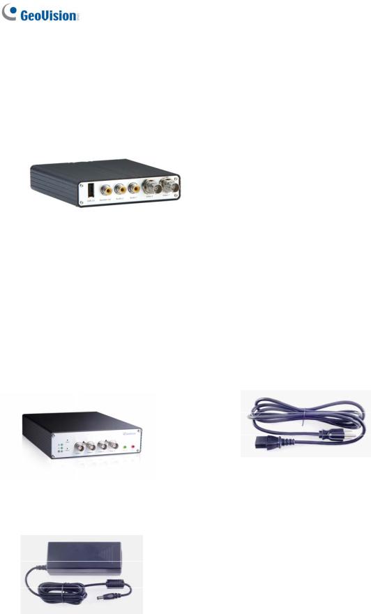
1.2.1 GV-VS04H / 14
1. GV-VS04H / GV-VS14
2. AC Power Cord
3. DC Male-to-Male Cable (for powering the camera through GV-Video Server)
4. Power Adaptor
5. Wall Hook
6. Conical Anchor x 4
7. Screw x 4
8. 3.5 mm Stereo to RCA Cable x 2
9. GV-Video Server Software CD/DVD
10. GV-NVR Software CD/DVD
Note: The DC Male-to-Male Cable is used to power the camera through the GV-Video Server. You can also optionally purchase three more DC Male-To-Mare Cables and one DC 1-Male to 4-Female Cable to power four cameras through the GV-Video Server.
1.2.2 GV-VS11
1. GV-VS11
2. Power Adaptor
3. GV-Video Server Software CD/DVD
4. GV-NVR Software CD/DVD
3
1.2.3 GV-VS12
1.2.4 GV-VS2420 / 2400
1. GV-VS2420 / 2400
3. Power Adaptor
4
1.GV-VS12
2.AC Power Cord
3.Power Adaptor
4.I/O Cable with RJ-45 Connector
5.Wall Hook
6.Conical Anchor x 4
7.Screw x 4
8.Sticker (for positioning conical anchors)
9.GV-Video Server Software CD/DVD
10.GV-NVR Software CD/DVD
2.AC Power Cord
4.Download Guide
5.Warranty Card
1 Introduction
1.2.5 GV-VS2401
1. GV-VS2401 |
2. AC Power Cord |
3. Power Adaptor |
4. |
Download Guide |
|
5. |
Warranty Card |
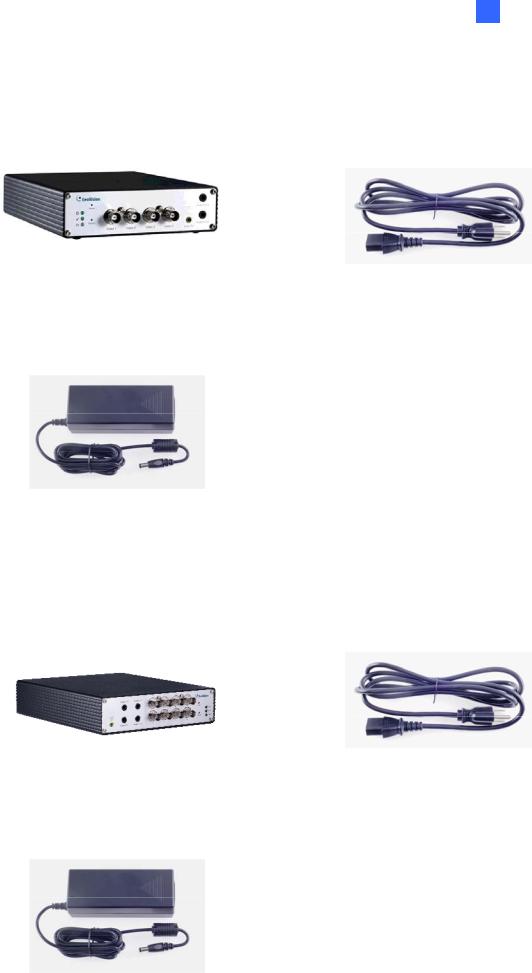
1.2.6 GV-VS2820 / 2800
1. GV-VS2820 / 2800 |
2. AC Power Cord |
3. Power Adaptor |
4. |
Download Guide |
|
5. |
Warranty Card |
5
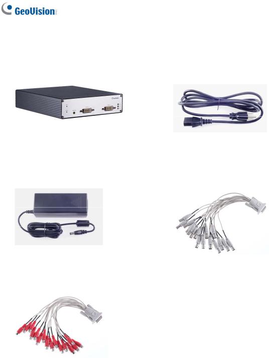
1.2.7 GV-VS21600
1. GV-VS21600 |
2. AC Power Cord |
3. Power Adaptor |
4. DVI to 16 Video BNC Breakout Cable |
5. DVI to 16 Audio RCA Breakout Cable |
6. |
Download Guide |
|
7. |
Warranty Card |
6

1 Introduction
1.3Compatible Products and System Requirements
1.3.1 Compatible GeoVision Software
This section introduces the compatible applications for GV-VS2420 / 2400 / 2401 / 2820 /
2800 / 21600.
|
|
|
|
Compatible |
|
|
VS2420 / 2400 |
|
|
VS2820 / 2800 |
|
|
VS2401 / 21600 |
|
|
|
|
|
Software |
|
|
|
|
|
|
|
|||
|
|
|
|
|
|
|
|
|
|
|
|
|
|
|
|
|
|
|
|
|
|
|
|
|
|
|
|
|
|
|
|
|
|
|
|
|
|
|
|
|
|
|
V8.7.4.0 with |
|
|
|
|
|
GV-DVR / NVR |
|
V8.6.2 with patch files or later |
|
patch files or |
||||||
|
|
|
|
|
|
|
|
|
|
|
|
|
later |
|
|
|
|
|
|
|
|
|
|
|
|
|
|||
|
|
|
|
|
|
|
V15.10 with |
|
V16.10.3.0 with |
|
V16.11.0.0 with |
|||
|
|
|
|
GV-VMS |
|
patch files or |
|
patch files or |
|
patch files or |
||||
|
|
|
|
|
|
|
later |
|
later |
|
later |
|||
|
Surveillance |
|
|
|
|
|
|
|
|
|
|
|
|
|
|
|
|
GV-Backup Center |
|
|
|
|
V1.2.0.0 or later |
|
|
|
|||
|
System and |
|
|
|
|
|
||||||||
|
GV-Control Center |
|
V3.4.0.0 with patch files or later |
|||||||||||
|
Network |
|
|
|
|
|
|
|
|
|
|
|
|
|
|
|
|
|
|
|
|
|
|
|
V16.11.0 with |
||||
|
Storage |
|
|
GV-Center V2 |
|
V16.10.0 with patch files or later |
|
|||||||
|
|
|
|
|
|
patch file or later |
||||||||
|
|
|
|
|
|
|
|
|
|
|
|
|
||
|
|
|
|
|
|
|
|
|
|
|
|
|
|
|
|
|
|
|
GV-Recording |
|
|
|
|
|
|
|
|
|
|
|
|
|
|
Server / Video |
|
V1.3.0.0 with patch files or later |
||||||||
|
|
|
|
Gateway |
|
|
|
|
|
|
|
|
|
|
|
|
|
|
|
|
|
|
|
|
|
|
|
|
|
|
|
|
|
GV-Redundant / |
|
V1.1.0.0 with patch files or later |
||||||||
|
|
|
|
Failover Server |
|
|||||||||
|
|
|
|
|
|
|
|
|
|
|
|
|
||
|
|
|
|
|
|
|
|
|
|
|
|
|
|
|
|
|
|
|
GV-Remote ViewLog |
|
V16.11.0 or later |
|
V16.11.0 with |
||||||
|
|
|
|
|
|
patch file or later |
||||||||
|
|
|
|
|
|
|
|
|
|
|
|
|
||
|
|
|
|
|
|
|
|
|
|
|||||
|
Mobile App |
|
|
GV-Eye |
|
V2.0 or later |
|
V2.3 or later |
||||||
|
|
|
|
|
|
|
|
|
|
|
|
|
|
|
|
Edge |
|
|
GV-Edge Recording |
|
|
|
|
|
|
|
V1.3.0.0 with |
||
|
|
|
Manager for |
|
V1.2.0.0 with patch files or later |
|
patch files or |
|||||||
|
Recording |
|
|
|
|
|||||||||
|
|
|
Windows |
|
|
|
|
|
|
|
later |
|||
|
|
|
|
|
|
|
|
|
|
|
||||
|
|
|
|
|
|
|
|
|
|
|
|
|
|
|
7

1.3.2 System Requirements
To access the Web interface of the GV-Video Server, ensure your PC is in good network connection and use one of the following Web browsers:
For GV-VS04H / 11 / 12 / 14
Microsoft Internet Explorer 7.x or later
For GV-VS2420 / 2400 / 2401 / 2820 / 2800 / 21600
Microsoft Internet Explorer 8.x or later
Google Chrome
Mozilla Firefox
Safari
Microsoft Edge
Note:
1.For the users of Internet Explorer 8 or later, additional settings are required. For details, see Appendix A.
2.Internet Explorer 10 is only supported by GV-VS11 version 1.05, GV-VS12 version 1.09 and GV-VS14 version 1.03.
3.For users of non-IE browsers using GV-VS2420 / 2400 / 2401 / 2800 / 2820 / 21600, download GV-Web Viewer to access full functioning user interface. For details, see 3.1 Accessing Your Surveillance Images.
1.4PoE Support
The models supporting PoE (Power over Ethernet) include:
GV-VS04H and GV-VS12
When the PoE (Power over Ethernet) function is used, please note:
The I/O terminal functions will not work. Don’t connect any devices to the I/O terminal block on the rear panel of the unit.
External power supply is required for USB storage device when used for recording.
See “Power over Ethernet” in Specifications later in this manual before purchasing a PoE adaptor.
8

1 Introduction
1.5GPS Support
Attached with the GV-GPS Receiver, the GV-Video Server allows you to perform vehicle tracking on Google Maps. The models supporting GPS function include:
GV-VS04H, GV-VS12 and GV-VS14.
Different models of the GV-Video Server support different interfaces:
UART: GV-VS04H and GV-VS14
RS-232: GV-VS12
9

1.6Options
Optional devices can expand your GV-Video Server’s capabilities and versatility. Contact your dealer for more information.
GV-GPS Receiver |
GV-GPS Receiver is a Global Position System |
|
receiver. With the GV-GPS Receiver, you can perform |
|
GPS tracking and location verification of the GV-Video |
|
Server. Two types of interfaces are available: UART |
|
(for GV-VS04H / 14) and RS-232 (for GV-VS12). |
|
Note: GV-GPS Receiver is only supported by |
|
GV-VS04H / 12 / 14. |
|
|
GV-Relay V2 |
Working with a GV-Relay V2, the GV-Video Server is |
|
capable of driving the loads of relay outputs over 5 |
|
volts. |
|
|
GV-WiFi Adaptor V2 |
Only supported by GV-VS2420 / 2400 (Firmware |
|
Version 1.03 or later) / 2401 / 2820 / 2800 / 21600. |
|
The WiFi Adaptor V2 is designed to connect GV IP |
|
devices, such as GV-Video Server, to the wireless |
|
network. |
|
|
GV-PA191 PoE Adaptor |
GV-PA191 is designed to provide power to the IP |
|
device through a single Ethernet cable. GV-PA191 is |
|
only supported by GV-VS04H / 12. |
|
|
GV-VR605A DC Voltage |
With a GV-VR605A, you can install the GV-Video |
Regulator |
Server in the car. GV-VR605A will supply and maintain |
|
a 12V voltage to the GV-Video Server and its |
|
connected cameras. |
|
Note: GV-VR605A is only supported by GV-VS04H / |
|
11 / 12 / 14. |
|
|
10
|
|
1 |
Introduction |
|
|
|
|||
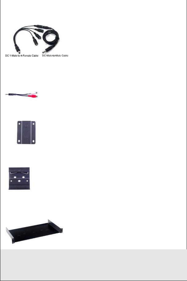
DC Male-to-Male Cable |
Only available for GV-VS2420 / 2400 / 2401, the DC |
|||
DC 1-Male to 4-Female Cable |
Male-to-Male Cable is used to power the camera |
|||
through the GV-Video Server. |
||||
|
||||
|
For instance, you can purchase four DC Male-to-Male |
|||
|
Cables and one DC 1-Male to 4-Female Cable to |
|||
|
power four cameras through the GV-Video Server. |
|||
|
|
|||
3.5 mm Stereo to |
Only supported by GV-VS2401 / 2820 / 2800, the 3.5 |
|||
RCA Cable |
mm Stereo to RCA Cable is served as an audio |
|||
adapter for microphones with RCA connectors. |
||||
|
||||
|
|
|||
Wall Hook |
Only supported by GV-VS2420 / 2400 / 2401 / 2820 / |
|||
|
2800 / 21600, the Wall Hook is used to mount the |
|||
|
device to the wall. |
|||
|
|
|||
Din-rail Hook |
Only supported by GV-VS2420 / 2400 / 2401 / 2820 / |
|||
|
2800 / 21600, the Din-rail Hook is used to mount the |
|||
|
device to a 35-mm (1.38-in) DIN rail. |
|||
|
|
|||
Rack Mount |
Only supported by GV-VS2420 / 2400 / 2401 / 2820 / |
|||
|
2800 / 21600, the Rack Mount is used to mount up to |
|||
|
3 GV-VS2420 / 2400 / 2401 or 2 GV-VS2820 / 2800 / |
|||
|
21600 video servers to a 19-inch (482.6-mm) rack. |
|||
|
|
|
|
|
Access Control Series
GV-Video Server can work with the Wiegand-interface card reader to send cardholder data to central monitoring stations, such as Center V2 and Vital Sign Monitor, as well as GV-DVR / NVR. The following devices are only supported by GV-VS04H / 14.
11

GV-Reader |
GV-Reader includes transmit-receive antenna and |
|
electronics. Featured with the Wiegand output, the unit |
|
is compatible with any standard access control panel. |
|
|
GV-R1352 Card Reader |
The GV-R1352 is a card reader designed to recognize |
|
identification cards. Featured with the Wiegand output, |
|
the unit can be connected to any standard access |
|
control panel. GV-R1352 comes with a weather-sealed |
|
and IP66 compliant housing for outdoor use. |
|
|
12
1 Introduction
1.7Physical Description
This section identifies the various components of the GV-Video Server.
1.7.1 Front View
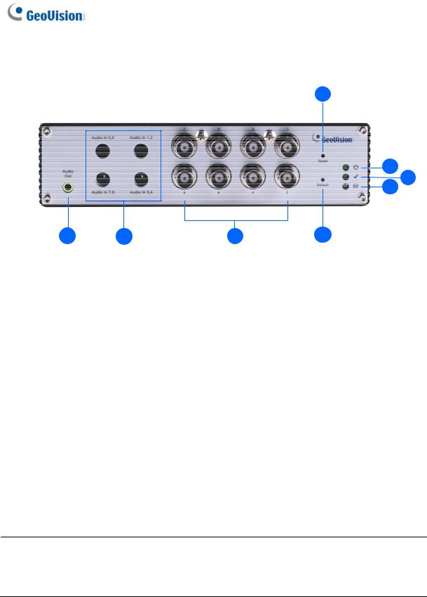
1.7.1.1 GV-VS04H / 14
Figure 1-1
13
No. |
Name |
Function |
|
|
|
|
|
1 |
Video Input |
4 plugs for video inputs. |
|
|
|
|
|
2 |
Speaker Output |
A plug for the speaker device. |
|
|
|
|
|
3 |
Audio Input |
Each plug is for 2 audio inputs. |
|
|
|
|
|
4 |
Reset |
It reboots the GV-Video Server, and keeps all current |
|
configurations. |
|||
|
|
||
|
|
|
|
5 |
Default Button |
It resets all configurations to their factory settings. See 6.4 |
|
Restoring to Factory Default Settings. |
|||
|
|
||
|
|
|
|
6 |
Disk Full/Fault |
This LED is on, indicating the hard drive is full or faulty. |
|
LED |
|||
|
|
||
|
|
|
|
7 |
Ready LED |
This LED is on, indicating the GV-Video Server is ready for |
|
connection. |
|||
|
|
||
|
|
|
|
8 |
Power LED |
This LED is on, indicating the power is supplied. |
|
|
|
|
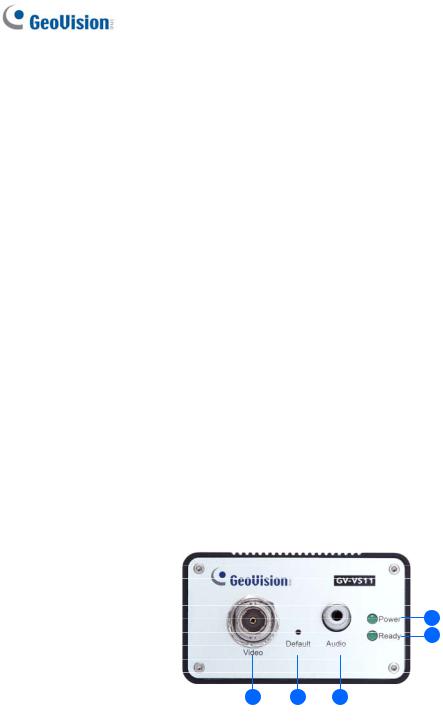
1.7.1.2GV-VS11
|
|
Figure 1-2 |
|
|
|
|
|
No. |
Name |
Function |
|
|
|
|
|
1 |
Video Input |
1 plug for video input. |
|
|
|
|
|
2 |
Default Button |
It resets all configurations to their factory settings. See 6.4 Restoring |
|
to Factory Default Settings. |
|||
|
|
||
|
|
|
|
3 |
Audio Input |
1 plug for audio input. |
|
|
|
|
|
4 |
Ready LED |
This LED is on, indicating the GV-Video Server is ready for |
|
connection. |
|||
|
|
||
|
|
|
|
5 |
Power LED |
This LED is on, indicating the power is supplied. |
|
|
|
|
|
14 |
|
|
1 Introduction
1.7.1.3GV-VS12
|
|
Figure 1-3 |
|
|
|
No. |
Name |
Function |
|
|
|
1 |
USB Port |
1 USB port for installing the portable storage device. |
|
|
|
2 |
Speaker Output |
A plug for the speaker device. |
|
|
|
3 |
Audio Input |
2 plugs for audio inputs. |
|
|
|
4 |
Video Input |
2 plugs for video inputs. |
|
|
|
15
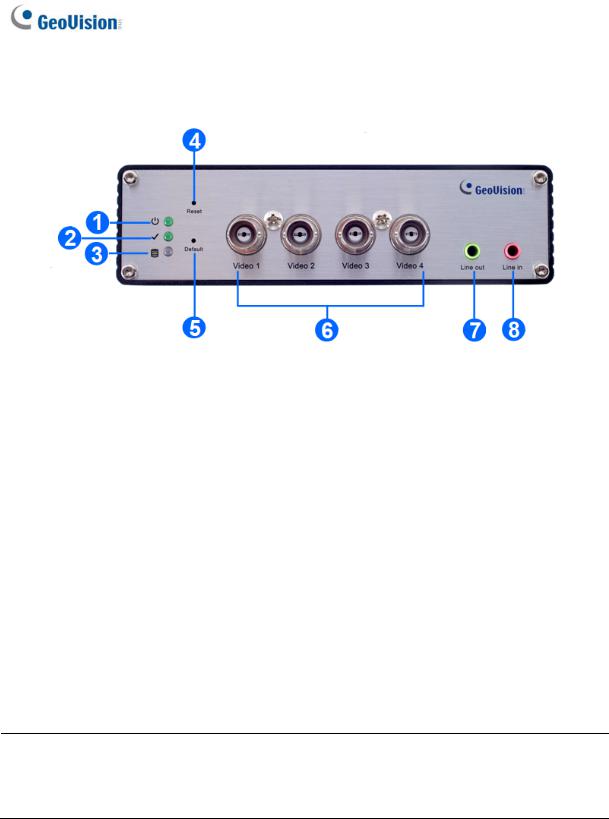
1.7.1.4GV-VS2420 / 2400
|
|
Figure 1-4 |
|
|
|
|
|
No. |
Name |
Function |
|
|
|
|
|
1 |
Power LED |
This LED is on, indicating the power is supplied. |
|
2 |
Ready LED |
This LED is on, indicating the GV-Video Server is ready for |
|
connection. |
|||
|
|
||
|
|
|
|
3 |
Disk Full/Fault |
This LED is on, indicating the hard drive is full or faulty. |
|
LED |
|||
|
|
||
|
|
|
|
4 |
Reset |
It reboots the GV-Video Server and keeps all current configurations. |
|
|
|
|
|
5 |
Default Button |
It resets all configurations to their factory settings. See 6.4 |
|
Restoring to Factory Default Settings. |
|||
|
|
||
|
|
|
|
6 |
Video Input |
4 plugs for video inputs. |
|
|
|
|
|
7 |
Line Out |
A plug for Video 1 speaker device. |
|
8 |
Line In |
A plug for Video 1 audio input. |
Note: When transmitting video signals over a long distance, it is highly recommended to use 5C-FB coaxial cables or above to minimize the degradation of image quality. The transmission distance should be within 300 m (984 ft).
16
1 Introduction
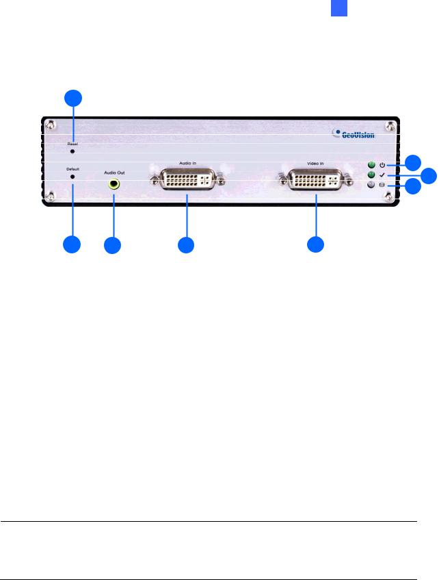
1.7.1.5GV-VS2401
|
|
Figure 1-5 |
|
|
|
|
|
No. |
Name |
Function |
|
|
|
|
|
1 |
Power LED |
This LED is on, indicating the power is supplied. |
|
2 |
Ready LED |
This LED is on, indicating the GV-Video Server is ready for |
|
connection. |
|||
|
|
||
|
|
|
|
3 |
Disk Full/Fault |
This LED is on, indicating the hard drive is full or faulty. |
|
LED |
|||
|
|
||
|
|
|
|
4 |
Reset |
It reboots the GV-Video Server and keeps all current configurations. |
|
|
|
|
|
5 |
Default Button |
It resets all configurations to their factory settings. See 6.4 |
|
Restoring to Factory Default Settings. |
|||
|
|
||
|
|
|
|
6 |
Video Input |
4 plugs for video inputs. |
|
|
|
|
|
7 |
Audio Out |
A plug for the speaker device. |
|
8 |
Audio In |
Each plug is for 2 audio inputs. |
|
|
|
|
Note: When transmitting video signals over a long distance, it is highly recommended to use 5C-FB coaxial cables or above to minimize the degradation of image quality. The transmission distance should be within 300 m (984 ft).
17
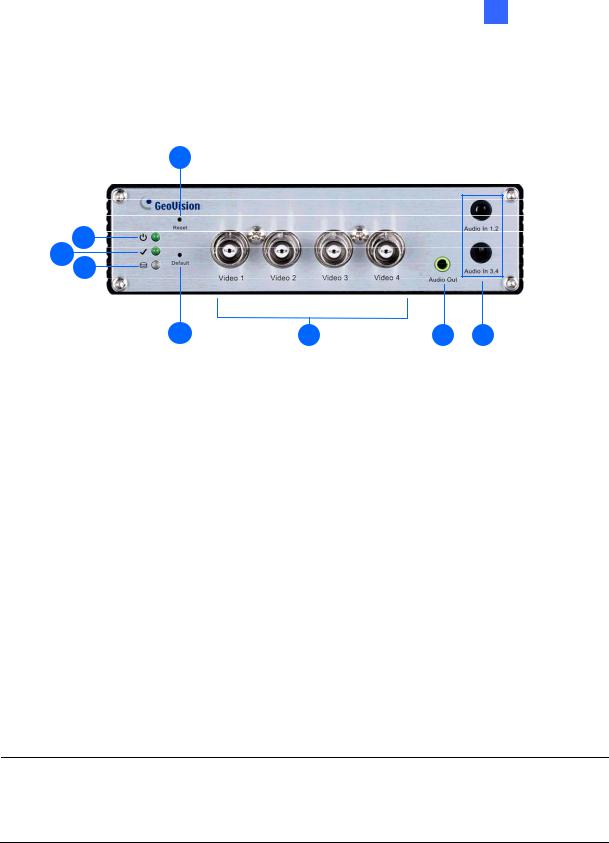
1.7.1.6GV-VS2820 / 2800
|
|
Figure 1-6 |
|
|
|
|
|
No. |
Name |
Function |
|
|
|
|
|
1 |
Audio Out |
A plug for the speaker device. |
|
2 |
Audio In |
4 plugs for max. 8 audio inputs. |
|
|
|
|
|
3 |
Video Input |
8 plugs for video inputs. |
|
4 |
Reset |
It reboots the GV-Video Server, and keeps all current |
|
configurations. |
|||
|
|
||
|
|
|
|
5 |
Default Button |
It resets all configurations to their factory settings. See 6.4 |
|
Restoring to Factory Default Settings. |
|||
|
|
||
|
|
|
|
6 |
Disk Full/Fault |
This LED is on, indicating the hard drive is full or faulty. |
|
LED |
|||
|
|
||
|
|
|
|
7 |
Ready LED |
This LED is on, indicating the GV-Video Server is ready for |
|
connection. |
|||
|
|
||
|
|
|
|
8 |
Power LED |
This LED is on, indicating the power is supplied. |
|
|
|
|
Note: When transmitting video signals over a long distance, it is highly recommended to use 5C-FB coaxial cables or above to minimize the degradation of image quality. The transmission distance should be within 300 m (984 ft).
18
1 Introduction
1.7.1.7GV-VS21600
|
|
Figure 1-7 |
|
|
|
|
|
No. |
Name |
Function |
|
|
|
|
|
1 |
Reset |
It reboots the GV-Video Server, and keeps all current configurations. |
|
2 |
Default Button |
It resets all configurations to their factory settings. See 6.4 Restoring to |
|
Factory Default Settings. |
|||
|
|
||
|
|
|
|
3 |
Audio Out |
A plug for the speaker device. |
|
4 |
Audio In |
A DVI plug connected with16 RCA ports for audio inputs. |
|
|
|
|
|
5 |
Video In |
A DVI plug connected with 16 BNC ports for video inputs. |
|
6 |
Disk Full/Fault |
This LED is on, indicating the hard drive is full or faulty. |
|
LED |
|||
|
|
||
|
|
|
|
7 |
Ready LED |
This LED is on, indicating the GV-Video Server is ready for connection. |
|
8 |
Power LED |
This LED is on, indicating the power is supplied. |
|
|
|
|
Note: When transmitting video signals over a long distance, it is highly recommended to use 5C-FB coaxial cables or above to minimize the degradation of image quality. The transmission distance should be within 300 m (984 ft).
19
1.7.2 Rear View
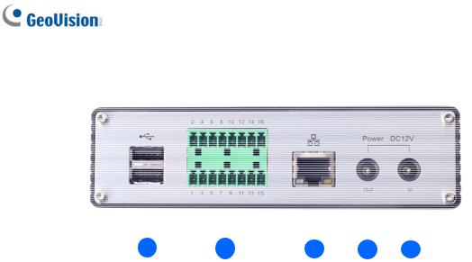
1.7.2.1GV-VS04H / 14
|
1 |
2 |
3 |
4 |
5 |
|
|
|
|
Figure 1-8 |
|
|
|
|
|
|
|
|
|
|
No. |
Name |
|
Function |
|
|
|
|
|
|
|
|
|
|
1 |
USB Port |
|
2 USB ports for installing portable storage devices. |
|||
|
|
|
|
|||
|
|
|
The connectors for digital inputs, relay outputs, PTZ cameras, |
|||
2 |
Terminal Block |
|
Wiegand device and GPS module control. See Chapter 9 Auxiliary |
|||
|
|
|
Device Connectors. |
|
|
|
|
|
|
A plug for a 10/100 Ethernet or PoE. |
|
||
3 |
Ethernet Port |
|
|
|
|
|
|
|
|
Note: GV-VS14 does not support PoE function. |
|||
|
|
|
A plug to power the camera, by using a DC Male-to-Male Cable, |
|||
|
|
|
directly through the GV-Video Server. |
|
||
4 |
Power Out |
|
|
|
|
|
|
|
|
Note: When PoE is applied, you cannot power the camera through |
|||
|
|
|
the GV-Video Server. |
|
|
|
5 |
Power In |
|
A plug for power input. |
|
|
|
20
1 Introduction
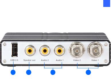
1.7.2.2GV-VS11
|
|
|
|
|
|
|
|
|
|
|
|
|
1 |
2 |
3 |
4 |
|||||
|
|
|
|
1 |
|
|
1 |
|||
|
|
|
|
Figure 1-9 |
|
|
||||
|
|
|
|
|
|
|
|
|
||
No. |
Name |
Function |
|
|
|
|
|
|
||
|
|
|
|
|
|
|
|
|
|
|
1 |
USB Port |
1 USB port for installing portable storage device. |
||||||||
|
|
|
||||||||
2 |
Ethernet Port |
A plug for inserting an Ethernet cable to build the network |
||||||||
connection. |
|
|
|
|
|
|
||||
|
|
|
|
|
|
|
|
|||
3 |
Terminal Block |
The connectors for digital input, digital output and PTZ camera |
||||||||
control. See Chapter 9 Auxiliary Device Connectors. |
||||||||||
|
|
|||||||||
4 |
Power In |
A plug for power input. |
|
|
|
|
||||
|
|
|
|
|
|
|
|
|
|
|
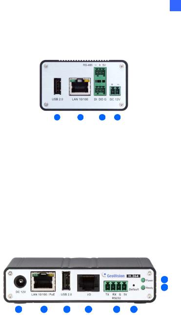
1.7.2.3GV-VS12
|
|
|
|
|
|
|
|
|
|
|
|
|
|
|
8 |
|
|
|
|
|
|
|
|
|
|
|
|
|
|
||||
|
|
|
|
|
|
|
|
|
|
|
|
|
|
7 |
||
|
|
|
|
|
|
|
|
|
|
|
|
|||||
|
|
|
|
|
|
|
|
|
|
|
|
|
|
|
|
|
|
|
|
|
|
|
|
|
|
|
|
|
|
|
|
|
|
|
|
|
|
|
|
|
|
|
|
|
|
|
|
|
|
|
|
1 |
2 |
3 |
4 |
5 |
6 |
|
|
|
|
||||||
|
|
|
|
|
Figure 1-10 |
|
|
|
|
|
|
|
|
|||
|
|
|
|
|
|
|
|
|
|
|
|
|
|
|
||
No. |
Name |
Function |
|
|
|
|
|
|
|
|
|
|
|
|
||
|
|
|
|
|
|
|
|
|
|
|
|
|
|
|
|
|
1 |
Power In |
A plug for power input. |
|
|
|
|
|
|
|
|
||||||
|
|
|
||||||||||||||
2 |
Ethernet Port |
A plug for a 10/100 Ethernet or PoE. |
||||||||||||||
|
|
|
||||||||||||||
3 |
USB Port |
1 USB port for installing the portable storage device. |
||||||||||||||
|
|
|
|
|||||||||||||
|
|
|
A port for digital input, relay output and PTZ camera control. Insert |
|||||||||||||
4 |
I/O / PTZ Port |
the I/O Cable with RJ-45 Connector to this port. See Chapter 9 |
||||||||||||||
|
|
|
Auxiliary Device Connectors. |
|
|
|
|
|
|
|||||||
|
|
|
||||||||||||||
5 |
RS-232 |
The connectors for GPS module control. See Chapter 9 Auxiliary |
||||||||||||||
Terminal Block |
Device Connectors. |
|
|
|
|
|
|
|
|
|||||||
|
|
|
|
|
|
|
|
|
||||||||
|
|
|
|
|||||||||||||
6 |
Default Button |
It resets all configurations to their factory settings. See 6.4 Restoring |
||||||||||||||
to Factory Default Settings. |
|
|
|
|
|
|
|
|
||||||||
|
|
|
|
|
|
|
|
|
|
|
||||||
7 |
Ready LED |
This LED is on, indicating the GV-Video Server is ready for |
||||||||||||||
connection. |
|
|
|
|
|
|
|
|
|
|
||||||
|
|
|
|
|
|
|
|
|
|
|
|
|
||||
|
|
|
||||||||||||||
8 |
Power LED |
This LED is on, indicating the power is supplied. |
||||||||||||||
|
|
|
|
|
|
|
|
|
|
|
|
|||||
|
|
|
|
|
|
|
|
|
|
|
21 |
|||||
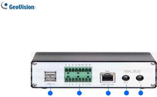
1.7.2.4GV-VS2420 / 2400
|
|
|
|
|
|
|
|
|
|
|
|
|
|
|
|
|
|
|
|
|
|
|
|
|
|
1 |
2 |
3 |
4 |
5 |
|||||
|
|
|
|
|
Figure 1-11 |
|
|
|
|
|
|
|
|
|
|
|
|
|
|
|
|
|
|
No. |
Name |
|
Function |
|
|
|
|
|
|
|
|
|
|
|
|
|
|
|
|
|
|
|
|
1 |
USB Port |
|
2 USB ports for installing portable storage devices. |
||||||||
|
|
|
|
||||||||
2 |
Terminal Block |
|
The connectors for digital inputs, digital outputs, and PTZ cameras. |
||||||||
|
See Chapter 9 Auxiliary Device Connectors. |
||||||||||
|
|
|
|||||||||
3 |
Gigabit Ethernet |
|
A plug for a 10/100/1000 Base-T Ethernet |
|
|
||||||
Port |
|
|
|
||||||||
|
|
|
|
|
|
|
|
|
|
|
|
|
|
|
|
||||||||
4 |
Power Out |
|
A plug to power the camera, by using the optional DC |
||||||||
|
Male-to-Male Cable, directly through the GV-Video Server |
||||||||||
|
|
|
|||||||||
5 |
Power In |
|
A plug for power input. |
|
|
|
|
|
|
||
|
|
|
|
|
|
|
|
|
|
|
|
22
Loading...