


GV-I/O Box 8 Ports
The GV-I/O Box 8 Ports provides 8 inputs and 8 relay outputs, and supports both DC and AC
output voltages.
Key Features
∙8 inputs and 8 outputs are provided.
∙Up to 9 pieces of GV-I/O Box 4/8/16 Ports can be chained together.
∙A USB port is provided for PC connection, and it is only used for 30 DC output voltage.
System Requirements
The GV-I/O Box is listed as XR21B1411 USB UART under Windows Device Manager, GV-
System version 8.5.7 or later is required.
To see how to check the device name under Windows Device Manager, refer to Installing
USB Driver later in this Installation Guide.
Packing List
1. |
GV-I/O Box 8 Ports x 1 |
3. |
Power Adapter DC 12V x 1 |
2. |
USB Cable (Type A to B) x 1 |
4. |
Software DVD x 1 |
Note: The GV-I/O box 8 Ports comes with the option of an Ethernet module. See
Accessing GV-I/O Box over Networks later in this Installation Guide.
September 10, 2014 |
1 |

Overview
B |
DIP Switch
The GV-I/O Box 8 Ports allows the use of mixing dry and wet contact devices together. The 8
inputs divided as four-in-one groups (A and B) are related to the 2 switches on the box for
dry and wet contact.
A B
1 |
2 |
ON |
E CE |
A B
1 |
2 |
ON |
E CE |
To change the inputs to different kind of contact, push the switch upward.
To change the inputs to different kind of contact, push the switch downward.
Note:
1.The RS-485 connectors do not support the conversion function from RS-485 to RS-232. Do not connect RS-485 devices, such as PTZ camera, to the connectors.
2.To add a GV-I/O Box 8 Ports to the GV-System of version 8.2, select GVIO-USB (16) from the Device drop-down list in the System Configure dialog box.
2 |
September 10, 2014 |
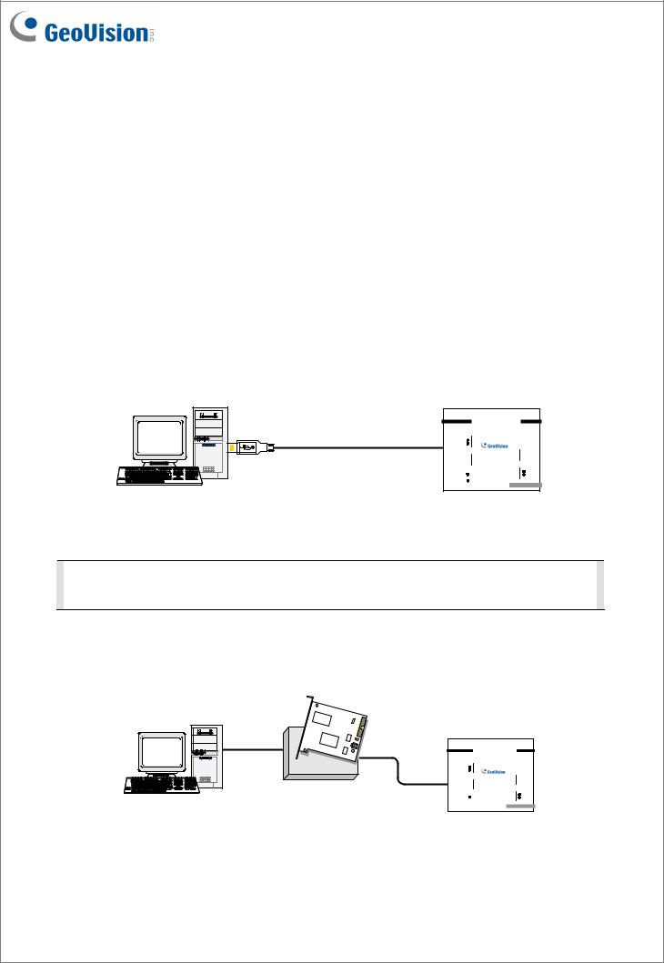
Connections to PC
There are three ways to connect a GV-I/O Box 8 Ports to the PC. Only one of the three
methods can be used at a time.
(1)USB cable: Use the USB cable to connect the PC.
(2)RS-485 wiring: Through the option of GV-Hub, GV-COM, GV-NET Card or GV-NET/IO Card, use the RS-485 connectors to connect the PC. RS-485 connection is suitable for long distance wiring up to 600 m / 1968.5 ft.
(3)Network: This is an optional function. See Accessing GV-I/O Box over Networks later in this Installation Guide.
1.Use the USB cable to connect one GV-I/O Box 8 Ports to the PC. (Allowed for DC
Output Voltage only)
Output
com.D
DO 8 

DO 7
D
DO 6
DO 5 

com.C
DO 4 

DO 3  C DO 2
DO 1 

RS485 RX 
RX485 TX
DC12V
Input
 USB RX
 USB TX
com .B

 DI 8
DI 8
B DI 7
DI 7
 DI 6
DI 6

 DI 5
DI 5
com .A

 DI 4
DI 4
DI 3
A
DI 2

 DI 1
DI 1
GV -IOBOX 8
Note: It is required to install the USB driver. See Installing USB Driver later in this Installation Guide.
2.Use the RS-485 connectors to connect one GV-I/O Box 8 Ports with the PC. (Allowed for AC/DC Output Voltage)
Output
com.D
DO 8 

DO 7
D
DO 6
DO 5 

com. C
DO 4 

DO 3  C DO 2
DO 1 

RS485 RX 
RX485 TX
DC12V 
Input
 USB RX
 USB TX
com .B

 DI 8
DI 8
B DI 7
DI 7
 DI 6
DI 6

 DI 5 com .A

 DI 4
DI 4
DI 3
A
DI 2

 DI 1
DI 1
GV -IOBOX 8
September 10, 2014 |
3 |

Installing USB Driver
To use the USB function, it is required to install the driver on the PC. Follow these steps to install the driver:
1.Insert the software DVD. It will run automatically and pop up a window.
2.Click Install GeoVision USB Devices Driver. This dialog box appears.
3.Click Install to install the drivers. When the installation is complete, this message will appear: Install Successfully.
4.Click Exit to close the dialog box and restart the PC.
To verify the drivers are installed correctly, go to Windows Device Manager after restarting
the PC. Expanding the Ports field, you should see XR21B1411 USB UART. The COM
number in the parenthesis indicates the COM port currently in use.
Note: If you unplug the GV-I/O Box 8 Ports from the PC and connect another GV-I/O Box to the same USB port, the COM port may still be changed. Access the Windows Device Manager again to look up the new COM port number.
4 |
September 10, 2014 |
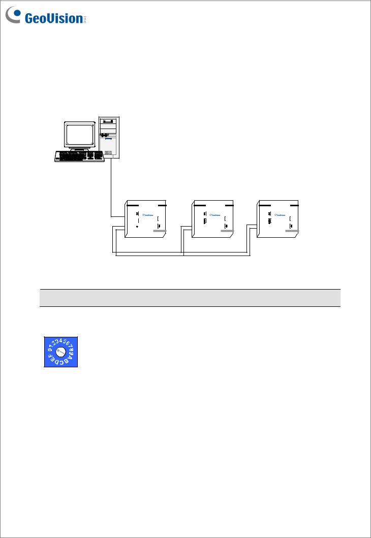
Assigning Addresses to GV-I/O Box
You can connect any GV-IO Box of 4, 8 and 16 ports together through RS-485 wiring. Up to 9 pieces of GV-I/O Box can be chained together to expand the I/O capacity. Use the ID switch (1~9) to assign addresses 1~9 to each GV-I/O Box.
Output
com.D
DO 8 

DO 7
D
DO 6
DO 5 

com.C
DO 4 

DO 3  C DO 2
DO 1 

RS485 RX 
RX485 TX
DC12V 
Input
 USB RX
 USB TX
com .B
 DI 8
DI 8
B DI 7
DI 7
 DI 6
DI 6
 DI 5
DI 5
com .A
 DI 4
DI 4
DI 3
A
DI 2
 DI 1
DI 1
GV -I OBOX 8
Output
com.D
DO 8 

DO 7
D
DO 6
DO 5 

com. C |
|
DO 4 |
|
DO 3 |
C |
DO 2 |
|
DO 1 |
|
RS485 RX 
RX485 TX 
DC12V 
Input
 USB RX
 USB TX
com .B
 DI 8
DI 8
B DI 7
DI 7
 DI 6
DI 6
 DI 5
DI 5
com .A
 DI 4
DI 4
DI 3
A
DI 2
 DI 1
DI 1
GV -IOBOX 8
Output
com.D
DO 8 

DO 7
D
DO 6
DO 5 

com. C |
|
DO 4 |
|
DO 3 |
C |
DO 2 |
|
DO 1 |
|
RS485 RX 
RX485 TX 
DC12V 
Input
 USB RX
 USB TX
com .B
 DI 8
DI 8
B DI 7
DI 7
 DI 6
DI 6
 DI 5
DI 5
com .A
 DI 4
DI 4
DI 3
A
DI 2
 DI 1
DI 1
GV -IOBOX 8
Note: The maximum distance for RS-485 connection is up to 600 m / 1968.5 ft.
ID Switch
1. Addresses 0 and A to F are NOT functional. 2. Assign the addresses when the power is off.
3.If you want to change the assigned address of the connected GV-I/O Box, set the switch to the new address, and then re-plug the power adaptor.
September 10, 2014 |
5 |
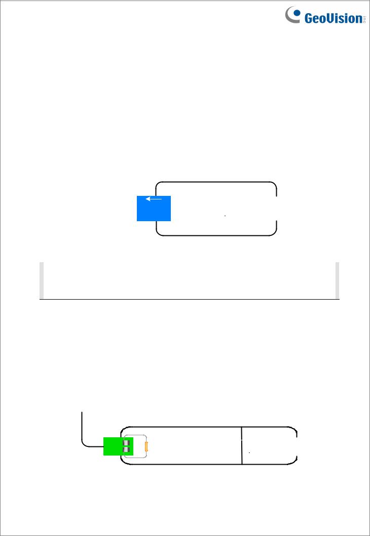
Extending Transmission over the Distance
When the transmission signals between the RS-485 communications become weak over the distance, switch on the Terminal Resistance Switches to maintain the signals. Three conditions below illustrate how the Terminal Resistance Switches should be switched on.
1.Multiple pieces of GV-I/O Box are connected with the PC through one single RS-485 cable.
After you connect multiple pieces of GV-I/O Box with the PC, switch on the Terminal
Resistance Switches in the first and last connected pieces of GV-I/O Box.
|
|
|
|
|
|
|
|
|
|
|
|
|
|
|
|
|
|
1 ON |
|
|
|
1 ON |
|
|
|
1 ON |
|
|
|
|
|
|
|
|
|
|
|
|
|
|
|
|||
|
|
|
|
|
|
|
|
|
|
|
|
|||
|
|
|
|
|
|
|
|
|
|
|
|
|
|
|
|
|
|
|
|
|
|
|
|
|
|
|
|
|
|
|
|
|
|
|
|
|
|
|
|
|
|
|
|
|
|
|
|
|
|
|
|
|
|
|
|
|
|
|
|
Note: If you connect GV-IO Box 4 Ports V1.2 as the first device to the PC, do not use the USB cable. Instead, use the RS-485 cable and you need the optional device, GVHub, GV-COM, GV-NET Card or GV-NET/IO, to connect the RS-485 device to the PC.
2.Multiple pieces of GV-I/O Box are connected with the PC through a RS-485 converter.
After you connect multiple pieces of GV-I/O Box with the PC through a RS-485 converter, such as GV-NET/IO Card and GV-Hub, insert a Terminal Resistor in the converter and switch on the Terminal Resistance Switch of the last connected GV-I/O Box.
|
|
|
|
|
|
|
|
|
|
|
|
|
|
|
|
|
|
|
|
|
|
|
|
|
|
|
|
|
|
|
|
|
|
|
|
|
|
|
|
|
|
|
|
ON |
|
|
|
ON |
|
|
|
|
|
|
|
|
|
|
|
|
|
|
|
|
|
||
|
|
|
|
|
|
|
|
|
|
|
|
|
|
|
||
|
|
|
|
|
|
|
|
|
|
|
|
|
|
|
|
|
|
|
|
|
|
|
|
|
|
|
|
|
|
|
|
|
|
|
|
|
|
|
|
|
|
|
|
|
|
|
|
|
|
|
6 |
September 10, 2014 |
 Loading...