


 Loading...
GV-IP Camera
Quick Start Guide
 Box Camera
 Ultra Box Camera
 Arctic Box Camera
 Target Box Camera
Before attempting to connect or operate this product, |
ICH265HISIV112-A |
please read these instructions carefully and save this manual for future use. |

© 2018 GeoVision, Inc. All rights reserved.
Under the copyright laws, this manual may not be copied, in whole or in part, without the written consent of GeoVision.
Every effort has been made to ensure that the information in this manual is accurate. GeoVision, Inc. makes no expressed or implied warranty of any kind and assumes no responsibility for errors or omissions. No liability is assumed for incidental or consequential damages arising from the use of the information or products contained herein. Features and specifications are subject to change without notice. Note: no memory card slot or local storage function for Argentina.
GeoVision, Inc.
9F, No. 246, Sec. 1, Neihu Rd.,
Neihu District, Taipei, Taiwan
Tel: +886-2-8797-8377
Fax: +886-2-8797-8335
http://www.geovision.com.tw
Trademarks used in this manual: GeoVision, the GeoVision logo and GV series products are trademarks of GeoVision, Inc. Windows is the registered trademark of Microsoft Corporation.
February 2018
Caution
Risk of explosion if battery is replaced by an incorrect type. Dispose of used batteries according to the instructions.
Safety Notice
The GV-IPCAM uses a Lithium battery as the power supply for its internal real-time clock (RTC). The battery should not be replaced unless required!
If the battery does need replacing, please observe the following:
Danger of Explosion if battery is incorrectly replaced
Replace only with the same or equivalent battery, as recommended by the manufacturer
Dispose of used batteries according to the manufacturer's instructions
Contents
Caution |
................................................................................. |
|
i |
Safety Notice ....................................................................... |
|
i |
|
Options .............................................................................. |
|
v |
|
Note for Adjusting Focus and Zoom.............................. |
vi |
||
Note for Installing Camera Outdoor.............................. |
vii |
||
Note for Closing the Bullet Camera Cover.................. |
viii |
||
Note for Silica Gel Bags ................................................ |
viii |
||
Note for Waterproofing Failures...................................... |
ix |
||
Note for Recording ............................................................ |
x |
||
Chapter 1 Bullet Camera (Part I)...................................... |
1 |
||
1.1 |
Packing List .............................................................................. |
3 |
|
1.2 |
Overview .................................................................................. |
4 |
|
1.3 |
Installation ................................................................................ |
5 |
|
|
1.3.1 Connecting the Camera ............................................... |
7 |
|
|
1.3.2 |
Adjusting the Angles .................................................. |
12 |
|
1.3.3 |
Adjusting Lens and Inserting a Memory Card............. |
16 |
|
1.3.4 |
Installing the Sun-Shield Cover .................................. |
19 |
1.4 |
Loading Factory Default.......................................................... |
20 |
|
|
1.4.1 |
Using the Web Interface............................................. |
20 |
|
1.4.2 |
Directly on the Camera .............................................. |
21 |
Chapter 2 Bullet Camera (Part II)................................... |
22 |
||
2.1 |
Packing List ............................................................................ |
25 |
|
2.2 |
Overview ................................................................................ |
27 |
|
i

2.3 |
Installation .............................................................................. |
30 |
2.4 |
Connecting the Camera.......................................................... |
37 |
Chapter 3 Bullet Camera (Part III).................................. |
40 |
||
3.1 |
Packing List ............................................................................ |
41 |
|
3.2 |
Overview ................................................................................ |
42 |
|
3.3 |
Installation .............................................................................. |
43 |
|
|
3.3.1 |
Adjusting the Angles .................................................. |
47 |
|
3.3.2 |
Adjusting Lens ........................................................... |
49 |
3.4 |
Connecting the Camera.......................................................... |
50 |
|
|
3.4.1 |
Wire Definition ........................................................... |
50 |
|
3.4.2. Power Connection..................................................... |
52 |
|
3.5 |
Loading Factory Default.......................................................... |
54 |
|
|
3.5.1. Using the Web Interface............................................ |
54 |
|
|
3.5.2. Directly on the Camera ............................................. |
54 |
|
Chapter 4 Ultra Bullet Camera....................................... |
55 |
||
4.1 |
Packing List ............................................................................ |
57 |
|
4.2 |
Overview ................................................................................ |
58 |
|
4.3 |
Installation .............................................................................. |
60 |
|
|
4.3.1 Waterproofing the Cable ............................................ |
65 |
|
|
4.3.2 Connecting the Camera ............................................. |
67 |
|
4.4 |
Loading Factory Default.......................................................... |
70 |
|
|
4.4.1 |
Using the Web Interface............................................. |
70 |
|
4.4.2 |
Directly on the Camera .............................................. |
70 |
Chapter 5 Target Bullet Camera (Part I)........................ |
71 |
|
5.1 |
Packing List ............................................................................ |
72 |
5.2 |
Overview ................................................................................ |
73 |
5.3 |
Installation .............................................................................. |
74 |
5.4 |
Connecting the Camera.......................................................... |
78 |
|
5.4.1 Wire Definition ........................................................... |
78 |
|
5.4.2 Power Connection...................................................... |
79 |
ii
5.5 Loading Factory Default.......................................................... |
80 |
|
5.5.1 |
Using the Web Interface............................................. |
80 |
5.5.2 |
Directly on the Camera .............................................. |
81 |
Chapter 6 Target Bullet Camera (Part II) |
.......................82 |
||
6.1 |
Packing List ............................................................................ |
83 |
|
6.2 |
Overview ................................................................................ |
84 |
|
6.3 |
Installation .............................................................................. |
85 |
|
|
6.3.1 |
Adjusting the Angles .................................................. |
90 |
|
6.3.2 |
Adjusting Lens ........................................................... |
91 |
6.4 |
Connecting the Camera.......................................................... |
92 |
|
|
6.4.1 |
Wire Definition ........................................................... |
92 |
|
6.4.2 Power Connection...................................................... |
93 |
|
6.5 |
Loading Factory Default.......................................................... |
94 |
|
|
6.5.1 |
Using the Web Interface............................................. |
94 |
|
6.5.2 |
Directly on the Camera .............................................. |
94 |
Chapter 7 Target Bullet Camera (Part III) |
......................95 |
||
7.1 |
Packing List ............................................................................ |
96 |
|
7.2 |
Overview ................................................................................ |
97 |
|
7.3 |
Installation .............................................................................. |
98 |
|
7.4 |
Connecting the Camera.......................................................... |
99 |
|
|
7.4.1 |
Wire Definition ........................................................... |
99 |
|
7.4.2 Power Connection...................................................... |
99 |
|
7.5 |
Loading Factory Default........................................................ |
100 |
|
|
7.5.1 |
Using the Web Interface........................................... |
100 |
|
7.5.2 |
Directly on the Camera ............................................ |
100 |
Chapter 8 Accessing the Camera................................ |
101 |
||
8.1 |
System Requirement ............................................................ |
101 |
|
8.2 |
Accessing the Live View ....................................................... |
102 |
|
|
8.2.1 |
Checking the Dynamic IP Address ........................... |
103 |
|
8.2.2 |
Configuring the IP Address ...................................... |
105 |
iii

8.3 Adjusting Image Clarity......................................................... |
107 |
Chapter 9 The Web Interface ....................................... |
110 |
Chapter 10 Upgrading System Firmware ..................... |
57 |
iv

Options
Optional devices can expand your camera’s capabilities and versatility. Contact your dealer for more information.
Device
I/O Cable
GV-Mount
Accessories
GV-PA191 PoE
Adapter
GV-POE Switch
Power Adapter
GV-Relay V2
Description
The I/O cable is a multi-connector providing I/O, DC 12V power, and audio connectivity for the camera. Length: 106.8 cm (3.5 ft)
The GV-Mount Accessories provide a comprehensive lineup of accessories for installation on ceiling, wall corner and pole. For details, see GV-Mount Accessories Installation Guide.
The GV-PA191 PoE adapter is designed to provide power and network connection to the cameras over a single Ethernet cable.
The GV-POE Switch is designed to provide power along with network connection for IP devices. The GV-POE Switch is available in various models with different numbers and types of ports.
The power adapter is available for all Bullet Camera, Ultra Bullet Camera (except GV-BL2511-E / 5311-E), and Target Bullet Camera. Contact our sales representatives for the countries and areas supported.
The GV-Relay V2 is designed to expand the voltage load of GV IP devices. It provides 4 relay outputs, and each can be set as normally open (NO) or normally closed (NC) independently as per your requirement.
v
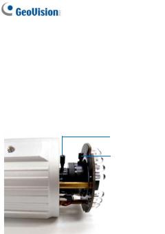
Note for Adjusting Focus and Zoom
When adjusting the Focus and Zoom Screws on Bullet Camera, do not over tighten the Focus and Zoom screws. The screws only need to be as tight as your finger can do it. It is not necessary to use any tools to get them tighter. Doing so can damage the structure of lens.
For example,
Zoom Screw
Focus Screw
The maximum torque value for all the zoom and focus screws is 0.049 N.m
vi
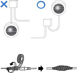
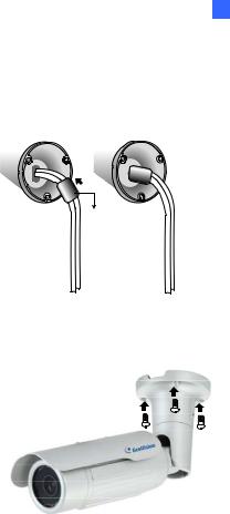
Note for Installing Camera Outdoor
When installing the cameras outdoor, be sure that:
1.The camera is set up above the junction box to prevent water from entering the camera along the cables.
2.Any PoE, power, audio and I/O cables are waterproofed using waterproof silicon rubber or the like.
vii
Note for Closing the Bullet Camera Cover
To ensure that the camera performs its full capacity against water and dust, tightly close and lock the camera cover as indicated below.
Note for Silica Gel Bags
1.The silica gel bag loses its effectiveness when the dry camera is opened. To prevent the lens from fogging up, replace the silica gel bag every time you open the camera, and conceal the gel bag in camera within 2 minutes of exposing to open air.
2.When the camera is shipped, a silica gel bag will be included inside the camera. For the first-time user, replace the silica gel bag prior to the installation to avoid foggy live view.
viii
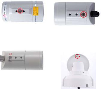
Note for Waterproofing Failures
To avoid waterproofing failures, do not open the screw on the camera body.
|
The screw on Ultra Bullet |
|
The screw on Target Bullet |
|
Camera |
|
Camera |
|
The screw on GV-EBL2101 / |
The screw on GV-BL3700 / |
|
2111 / 3101 / 5101 |
5700 |
ix

Note for Recording
1.By default, the images are recorded to the memory card inserted in the GV-IP Camera (except GV-IR Arctic Box Camera, which is not equipped with a memory card slot). Make sure the Write recording data into local storage option (see 4.1.1 Video Settings, GV-IPCam Firmware Manual) is enabled. If this option is disabled, the camera will stop recording to the memory card while the live view is accessed through Web browsers or other applications.
2.Mind the following when using a memory card for recording:
Recorded data on the memory card can be damaged or lost if the data are accessed while the camera is under physical shock, power interruption, memory card detachment or when the memory card reaches the end of its lifespan. No guarantee is provided for such causes.
The stored data can be lost if the memory card is not accessed for a long period of time. Back up your data periodically if you seldom access the memory card.
Memory cards are expendable and their durability varies according to the conditions of the installed site and how they are used. Back up your data regularly and replace the memory card annually.
Replace the memory card when its read/write speed is lower than 6 MB/s or when the memory card is frequently undetected by the camera.
3.It is recommended to use memory cards of the following setting and specifications:
Apply a battery backup (UPS) to avoid power outage.
Use Micro SD card of MLC NAND flash, Class 10 for better performance.
x

1 Bullet Camera (Part I)
Chapter 1 Bullet Camera (Part I)
The Bullet Cameras are specifically designed for outdoors and are weatherproof (IP66 or IP67). They are equipped with IR LEDs for infrared illumination in night vision applications. The models described in this chapter use auto iris, which allows for automatic control of exposure.
The WDR Pro models enhance the image by processing contrasting intensity of light. The super low lux models can produce color live view in near darkness. The motorized varifocal lens models allow the user to adjust the focus and zoom through the Web interface.
1
Model No. |
|
|
Specifications |
|
GV-BL120D |
|
|
|
|
GV-BL130D |
|
|
|
|
GV-BL220D |
|
|
|
|
GV-BL320D |
|
|
Auto Iris, f: 3 ~ 9 |
|
GV-BL1500 |
|
Varifocal |
mm, F/1.2, 1/2.7’’ |
|
|
lens |
ø 14 mm Lens |
||
|
|
|||
GV-BL2400 |
|
|
Mount |
|
|
|
|
|
|
GV-BL2500 |
|
|
|
|
|
|
|
|
|
GV-BL3400 |
|
|
|
|
GV-BL1210 |
|
|
|
Auto Iris, |
|
|
|
|
|
|
|
|
f: 3 ~ 9 mm, |
|
GV-BL2410 |
|
|
F/1.2, 1/2.7’’ |
|
|
|
Motorized |
ø 14 mm Lens |
|
GV-BL3410 |
|
Mount |
||
|
varifocal |
|||
|
|
|
||
|
|
lens |
|
|
|
|
Auto Iris, |
||
|
|
|
||
|
|
|
f: 4.5 ~ 9 mm, |
|
GV-BL5310 |
|
|
F/1.2, 1/2.7’’ |
|
|
|
|
ø 14 mm Lens |
|
|
|
|
Mount |
|
Description
1.3MP, H.264, Low Lux
1.3MP, H.264
2 MP, H.264
3 MP, H.264
1.3 MP, H.264, Super
Low Lux
2 MP, H.264, WDR Pro
2 MP, H.264, Super Low
Lux
3 MP, H.264, WDR Pro
1.3 MP, H.264, Low Lux,
3X Optical Zoom
2 MP, H.264, WDR Pro,
3X Optical Zoom
3 MP, H.264, WDR Pro,
3X Optical Zoom
5 MP, H.264, 2X Optical
Zoom
2

1 Bullet Camera (Part I)
1.1 Packing List
Bullet Camera
Self Tapping Screw x 3
Plastic Screw Anchor x 3
Torx Wrench x 2
Sun-Shield Cover Kit (Sun-Shield Cover, Philips Head Screw x 2, Plastic Screw Spacer x 2 and Hexagon Screw x 2)
Silica Gel Bag x 2
2-Pin Terminal Block
Power Adapter
Download Guide
Warranty Card
Note: The power adapter can be excluded upon request.
3
1.2 Overview
1 |
2 |
3 |
4 |
||||
|
|
|
|
|
|
|
|
|
|
|
|
|
|
|
|
|
|
|
|
|
|
|
|
|
|
|
|
|
|
|
|
|
|
|
|
|
|
|
|
|
|
|
|
Figure 1-1 |
|
|
|
|
|
|
|
No. |
|
|
Name |
|
Description |
1 |
|
|
Memory Card Slot |
|
Receives a micro SD card (SD/SDHC, |
|
|
|
version 2.0 only, Class 10). |
||
|
|
|
|
|
|
2 |
|
|
Zoom Screw |
|
Holds the zoom lens in place. |
3 |
|
|
Focus Screw |
Holds the focus lens in place |
|
4 |
|
|
Default Button |
|
Resets all configurations to factory default. |
|
|
|
For details, see 1.4 Loading Factory Default. |
||
|
|
|
|
|
|
4
1 Bullet Camera (Part I)
1.3 Installation
These instructions describe the basic installation of the Bullet Camera.
1.Slide the cable clamp to the camera base.
Cable Clamp
Figure 1-2
2.Install the Bullet Camera to the wall.
Figure 1-3
3.Remove the protection sticker from the camera’s cover.
4.Connect the power, network and other wires to the Bullet Camera. See 1.3.1 Connecting the Camera.
5

5.Access the live view. For details, see 8.2 Accessing the Live View.
6.Adjust angles of the camera body based on the live view. Three shafts can be adjusted. See 1.3.2 Adjusting the Angles.
7.Loosen the camera’s cover, adjust the focus of the camera and optionally insert a micro SD card (SD/SDHC, version 2.0, Class 10) into the SD card slot. See 1.3.3 Adjusting Lens and Inserting a Memory Card.
8.Fasten the camera’s cover.
9.Install the sun-shield cover to the Bullet Camera. For details, see
1.3.4 Installing the Sun-Shield Cover.
6
1 Bullet Camera (Part I)
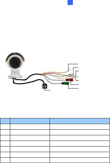
1.3.1 Connecting the Camera
Wire Definition for Auto Iris Models
The 7-Pin Data Cable provides connections for power, ground, 1 sensor input, 1 alarm output, audio input and audio output. The wires are illustrated and defined below:
|
|
|
Digital In (Red) |
|
|
|
DC 12V+ / AC 24V + (Brown) |
|
|
|
Digital Out (Orange) |
|
|
|
DC 12V- / AC 24V - (Black) |
|
|
|
GND (Yellow) |
|
|
|
Audio In (Red) |
|
|
Ethernet (PoE) |
Audio Out (Green) |
|
|
|
|
|
|
Figure 1-4 |
|
No. |
Wire Color |
Definition |
|
1 |
Red |
Digital In |
|
2 |
Brown |
DC 12V+ / AC 24V+ |
|
3 |
Orange |
Digital Out |
|
4 |
Black |
DC 12V- / AC 24V- |
|
5 |
Yellow |
Ground |
|
6 |
Red RCA |
Audio in |
|
7 |
Green RCA |
Audio out |
|
7
Note that the Audio In and Out connectors may also come as terminal blocks:
Ethernet (PoE) |
Digital In (Red)
DC 12V+ / AC 24V + (Brown)
Digital Out (Orange)
DC 12V- / AC 24V - (Black)
 GND (Yellow)
Audio In (Brown)
Audio Out (Green)
|
|
Figure 1-5 |
|
|
|
|
|
No. |
Wire Color |
|
Definition |
1 |
Red |
|
Digital In |
2 |
Brown |
|
DC 12V+ / AC 24V+ |
3 |
Orange |
|
Digital Out |
4 |
Black |
|
DC 12V- / AC 24V- |
5 |
Yellow |
|
Ground |
6 |
Brown terminal block |
|
Audio in |
7 |
Green terminal block |
|
Audio out |
8
1 Bullet Camera (Part I)
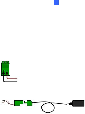
Power Connection
Use one of the following methods to supply power to the camera.
Use a Power over Ethernet (PoE) adapter to connect the camera to the network, and the power will be provided at the same time.
Plug the power adaptor to the terminal block as shown below.
Insert the black wire of the Bullet Camera to the left pin (+) and the brown wire to the right pin (-).
Figure 1-6
Connect the DC 12V Power Adapter to the Terminal Block.
Terminal Block |
DC 12V Power Adaptor |
Figure 1-7
9
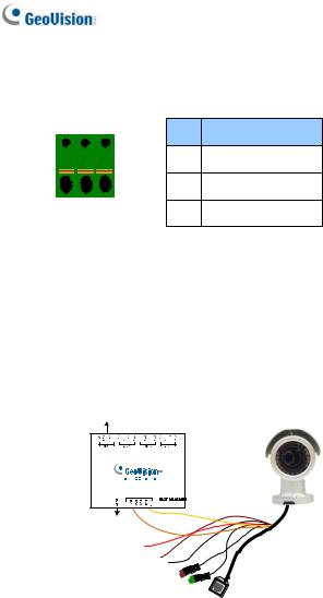
I/O Device Connection
The camera supports one digital input and one digital output of dry contact.
|
I/O |
|
Pin |
Function |
|
|
|
|
|||
|
|
|
1 |
Digital Output |
|
|
|
|
2 |
GND |
|
1 |
2 |
3 |
3 |
Digital Input |
|
Figure 1-8 |
|||||
|
|
||||
For details on how to enable an installed I/O device, see 4.2 I/O Settings, GV-IPCam Firmware Manual.
Voltage Load Expansion (Optional)
The camera can only drive a maximum load of 200mA 5V DC. To expand the maximum voltage load to 10A 250V AC, 10A 125V AC or 5A 100V DC, connect the camera to a GV-Relay V2 module (optional product). Refer to the figure and table below.
Output Devices
Connect to Power
Figure 1-9
10
|
|
1 |
Bullet Camera (Part I) |
|
|
|
|
||
GV-Relay V2 |
Bullet Camera |
|
||
COM |
Ground (Yellow) |
|
||
DO1 |
Digital Out (Orange) |
|
||
11
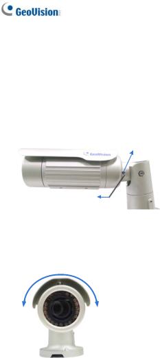
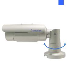
1.3.2 Adjusting the Angles
The Bullet Camera is designed to be adjustable in three shafts for easy and flexible installation.
First Shaft
You can adjust the camera body by 360 degrees to the right or the left.
1.Unscrew the panning lock screw with the torx wrench.
Panning Lock Screw
Torx Wrench
Figure 1-10
2.Adjust the angle of camera body to the right or the left, and fasten the panning lock screw.
0 ~ 360°
Figure 1-11
12
1 Bullet Camera (Part I)
Second Shaft
You can adjust the camera body up and down by 90, 112.5, 135, 157.5 or 180 degrees by using the gears inside the camera body and the camera base.
1.Unscrew the tilting lock screw with the torx wrench.
Tilting Lock Screw
Torx Wrench
Figure 1-12
2.Hold the camera body, and move the camera base to the right to separate the camera gears.
Move the Camera
Base to the Right
|
|
|
Camera Body |
Camera Gears |
|
|
|
|
Figure 1-13
13
3.Adjust the angle of camera body to 90°, 112.5°, 135°, 157.5° or 180°. Then move the camera base to the left to combine the gears.
180 ° 157.5° |
135 ° |
112.5° |
90° |
Figure 1-14
4.Fasten the tilting lock screw.
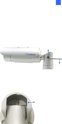
Third Shaft
You can adjust the camera base by 360°.
1.Unscrew the base fixing screw with the torx wrench.
Torx Wrench
Base Fixing Screw
Figure 1-15
14
1 Bullet Camera (Part I)
2.Adjust the angle of camera base, and fasten the base fixing screw.
0~360°
Figure 1-16
15
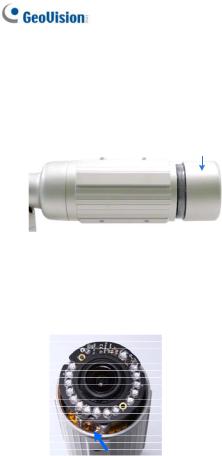
1.3.3 Adjusting Lens and Inserting a Memory Card
To adjust the camera’s zoom and focus or to insert a micro SD card (SD/SDHC, version 2.0 only, Class 10), follow the steps below.
1.Loosen the camera’s cover.
Camera’s Cover
Figure 1-17
For GV-BL2511-E / 5311-E, loosen the camera’s cover and the screw as indicated below.
Figure 1-18
16
1 Bullet Camera (Part I)
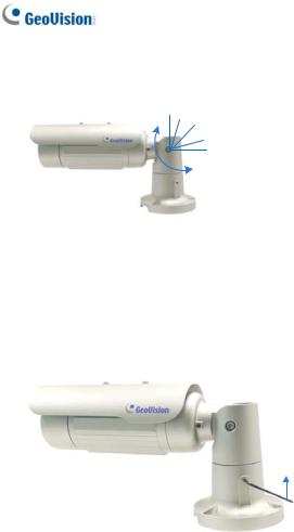
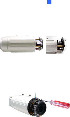
2.To adjust for image clarity, follow the steps below.
For models with zoom and focus screws, pull out the camera and remove the silica gel bag to access its focus and zoom screws. Use GV-IP Device Utility to help you. For details, see 8.3 Adjusting Image Clarity.
Silica Gel Bag |
|
|
|
|
|
|
|
|
Zoom Screw |
||
|
|
|
|
|
|
|
|
|
|
|
|
|
|
|
|
|
Focus Screw |
|
|
|
|
|
|
Figure 1-19
For motorized varifocal lens models, adjust for image clarity through the Web interface. For details, see Zoom, Focus Change, and Focus Mode settings in 3.2.2 The Control Panel of the Live View Window, GV-IPCam Firmware Manual.
3.To insert a micro SD card, follow the steps below.
4.Loosen the fixing screw.
Fixing Screw
Figure 1-20
5.Slightly pull out the camera module.
17
Loading...