


 Loading...
GV-SNVR System
User’s Manual
SNVR-UM-D

© 2019 GeoVision, Inc. All rights reserved.
Under the copyright laws, this manual may not be copied, in whole or in part, without the written consent of GeoVision.
Every effort has been made to ensure that the information in this manual is accurate. GeoVision, Inc. makes no expressed or implied warranty of any kind and assumes no responsibility for errors or omissions. No liability is assumed for incidental or consequential damages arising from the use of the information or products contained herein. Features and specifications are subject to change without notice.
Note: No memory card slot or local storage function for Argentina.
GeoVision, Inc.
9F, No. 246, Sec. 1, Neihu Rd., Neihu District, Taipei, Taiwan Tel: +886-2-8797-8377
Fax: +886-2-8797-8335 http://www.geovision.com.tw
Trademarks used in this manual: GeoVision, the GeoVision logo and GV series products are trademarks of GeoVision, Inc. Windows is the registered trademark of
Microsoft Corporation.
September 2019

Preface
Welcome to the GV-SNVR System User’s Manual.
The GV-SNVR System has a series of models designed to meet different needs. This manual is designed for the following models:
Models
GV-SNVR0400F
GV-SNVR0411
GV-SNVR0412
GV-SNVR0811
GV-SNVR0812
GV-SNVR1600
GV-SNVR1611
Caution
The GV-SNVR System is designed for indoor use only.
i

Contents
Chapter 1 Introduction........................................................................................... |
1 |
||
1.1 |
Features |
........................................................................................................ |
2 |
1.2 |
Models .......................................................................................................... |
|
3 |
1.3 |
Packing List .............................................................................and Package |
3 |
|
|
1.3.1 .......................................................................... |
GV - SNVR Single Package |
4 |
|
............................................................................. |
GV - SNVR0400F |
4 |
|
............................................................................... |
GV - SNVR0411 |
4 |
|
............................................................................... |
GV - SNVR0412 |
5 |
|
............................................................................... |
GV - SNVR0811 |
5 |
|
............................................................................... |
GV - SNVR0812 |
6 |
|
............................................................................... |
GV - SNVR1600 |
6 |
|
............................................................................... |
GV - SNVR1611 |
7 |
|
1.3.2 ...................................................................... |
GV - SNVR Bundled Package |
7 |
|
............................................................................. |
GV - SNVR0400F |
7 |
1.4 |
Compatible .........................................Products and System Requirements |
8 |
|
|
1.4.1 ............................................................. |
Supported GV - IP Cameras |
8 |
|
1.4.2 ................................................. |
Supported GeoVision Applications |
9 |
|
1.4.3 .................................................................. |
System Requirements |
10 |
1.5 |
Optional .................................................................................Accessories |
11 |
|
1.6 |
Overview.................................................................................................... |
12 |
|
|
1.6.1 .................................................................................... |
Front View |
12 |
|
1.6.2 ..................................................................................... |
Rear View |
18 |
Chapter 2 Getting Started.................................................................................... |
25 |
||
2.1 |
Installation.................................................................................................. |
25 |
|
|
2.1.1 |
GV-SNVR0411 ............................................................................. |
25 |
|
2.1.2 |
GV-SNVR0811 .............................................................................................. |
27 |
|
2.1.3 |
GV-SNVR0400F ........................................................................................... |
29 |
|
2.1.4 |
GV-SNVR1600 ............................................................................. |
31 |
|
2.1.5 |
GV-SNVR1611 .............................................................................................. |
33 |
|
2.1.6 |
GV-SNVR0412 / 0812................................................................................. |
35 |
2.2 |
Connecting the GV-SNVR.......................................................................... |
37 |
|
|
2.2.1 Network Connection for GV-SNVR1600....................................... |
41 |
|
|
2.2.2 |
Accessing the GV-SNVR.............................................................. |
42 |
ii
2.3 |
Setting Up IP Cameras .............................................................................. |
43 |
|
|
2.3.1 Automatically Setting Up IP Cameras .......................................... |
43 |
|
|
2.3.2 Manually Connecting GV-IP Cameras.......................................... |
45 |
|
|
2.3.3 Manually Connecting Third-Party IP Cameras ............................. |
46 |
|
|
2.3.4 Changing Camera IP Address and Assigning Channels............... |
48 |
|
2.4 |
Formatting Hard Drive................................................................................ |
49 |
|
2.5 |
Main Screen............................................................................................... |
51 |
|
2.6 |
Enabling Recording.................................................................................... |
53 |
|
2.7 |
Playing Back Video .................................................................................... |
53 |
|
2.8 |
Live Monitoring........................................................................................... |
54 |
|
|
2.8.1 |
Snapshot ...................................................................................... |
54 |
|
2.8.2 |
Audio ............................................................................................ |
55 |
|
2.8.3 |
PTZ Control .................................................................................. |
57 |
|
2.8.4 |
Digital PTZ Function ..................................................................... |
58 |
|
2.8.5 |
Fisheye Dewarping ...................................................................... |
59 |
|
2.8.6 |
Image Orientation ......................................................................... |
60 |
Chapter 3 System Configuration ........................................................................ |
61 |
||
3.1 |
Camera |
....................................................................................................... |
61 |
|
3.1.1 ................................................................ |
GV - IP Camera Settings |
61 |
|
3.1.2 .....................................Third-Party IP Camera Settings (ONVIF) |
64 |
|
3.2 |
Recording.................................................................................................... |
66 |
|
3.3 |
Network....................................................................................................... |
|
67 |
|
3.3.1 ................................................................................... |
WAN / LAN |
67 |
|
3.3.2 .............................................................................................. |
WiFi |
71 |
|
3.3.3 ........................................................................................... |
DDNS |
72 |
|
3.3.4 ........................................................................................... |
E - Mail |
73 |
|
3.3.5 .................................................................................. |
Web Server |
74 |
3.4 |
Storage ....................................................................................................... |
|
75 |
3.5 |
Display ........................................................................................................ |
|
75 |
3.6 |
Service........................................................................................................ |
|
77 |
3.6.1Connecting GV-SNVR with GV-Center V2 and GV-Vital Sign
|
Monitor..................................................................................................... |
77 |
|
3.6.2 Connecting GV-Eye to GV-SNVR................................................. |
78 |
|
3.6.3 Connecting GV-Cloud Center to GV-SNVR.................................. |
79 |
3.7 |
Event........................................................................................................... |
80 |
3.8 |
System........................................................................................................ |
82 |
|
|
iii |

Chapter 4 |
Video Playback ................................................................................... |
87 |
||
4.1 |
Timeline Player ........................................................................................... |
87 |
||
4.2 |
Recording Backup...................................................................................... |
89 |
||
Chapter 5 Remote Access to the GV-SNVR ....................................................... |
90 |
|||
5.1 |
Accessing through Web browser ................................................................ |
91 |
||
|
|
5.1.1 |
Live View Screen.......................................................................... |
92 |
|
|
5.1.2 Camera Settings via Web............................................................. |
94 |
|
|
|
5.1.3 Snapshot of Live Video ................................................................ |
95 |
|
|
|
5.1.4 |
Picture-in-Picture View ................................................................. |
96 |
|
|
5.1.5 |
Picture-and-Picture View.............................................................. |
97 |
|
|
5.1.6 |
Digital PTZ Control....................................................................... |
98 |
|
|
5.1.7 |
Fisheye View ................................................................................ |
99 |
5.2 |
Accessing through SNVR Viewer.............................................................. |
102 |
||
|
|
5.2.1 Live View through SNVR Viewer ................................................ |
104 |
|
|
|
5.2.2 Playback through SNVR Viewer................................................. |
106 |
|
|
|
5.2.3 Snapshot & Video Export through SNVR Viewer ....................... |
108 |
|
5.3 |
Accessing through Mobile Device ............................................................. |
109 |
||
5.4 |
Accessing through GV-Edge Recording Manager..................................... |
109 |
||
5.5 |
Accessing through GV-Control Center ...................................................... |
110 |
||
5.6 |
Accessing through RTSP .......................................................................... |
110 |
||
Chapter 6 |
Advanced Applications ..................................................................... |
111 |
||
6.1 |
Upgrading System Firmware ................................................................... |
111 |
||
|
|
6.1.1 Safe Mode of GV-SNVR1611 ..................................................... |
112 |
|
6.2 |
Using the GV-IP Device Utility.................................................................. |
113 |
||
|
|
6.2.1 |
Looking Up the IP Address......................................................... |
113 |
|
|
6.2.2 Accessing the Live View............................................................. |
113 |
|
|
|
6.2.3 |
Upgrading System Firmware...................................................... |
114 |
|
|
6.2.4 Backing Up and Restoring Settings............................................ |
115 |
|
|
|
6.2.5 Restoring to Factory Default Settings......................................... |
117 |
|
Appendix |
................................................................................................................ |
|
118 |
|
iv

Chapter 1 Introduction
GV-SNVR is an H.264/H.265 Linux-embedded Standalone Network Video Recorder that records video files directly to the internal hard drive, supporting up to 4 / 8 / 16 channels of IP cameras for network surveillance. With the feature of a Full HD HDMI video output, the GV-SNVR eliminates the need of a separate PC to view and play back video images from the unit. Its USB ports allow you to connect a USB flash drive to import or export system settings, update firmware, save snapshot files and back up videos in AVI format.
Optionally, you can connect a GV-Joystick V2 to control connected PTZ cameras. In addition, you can remotely access the live view and recorded videos through mobile devices, SNVR Viewer or Web browsers with advanced video features.
Figure 1-1
1

1Introduction
1.1 Features
˙4-Channel video recording (for GV-SNVR0400F / 0411 / 0412)
˙8-Channel video recording (for GV-SNVR0811 / 0812)
˙16-Channel video recording (for GV-SNVR1600 / 1611)
˙Automatic search and setup of IP cameras
˙Support for third-party IP cameras through ONVIF and RTSP (for GV-SNVR0411 / 0412 / 0811 / 0812 / 1611)
˙4-Port PoE (IEEE 802.3af) for camera connection (for GV-SNVR0411)
˙4-Port PoE+ (IEEE 802.3at) for camera connection (for GV-SNVR0412)
˙8-Port PoE+ (IEEE 802.3at) for camera connection (for GV-SNVR0811 / 0812)
˙16-Port PoE+ (IEEE 802.3at) for camera connection (for GV-SNVR1611)
˙Video Resolution
|
Model |
|
|
Resolution |
|
GV-SNVR0411 / 0412 / 0811 |
|
|
Up to 3840 x 2160 per channel * |
|
/ 0812 |
|
|
|
|
GV-SNVR1611 |
|
|
Up to 4000 x 3000 per channel * |
|
GV-SNVR0400F |
|
|
Up to 1920 x 1080 per channel * |
|
GV-SNVR1600 |
|
|
Up to 2592 x 1944 for the first channel * |
|
|
|
Up to 1920 x 1080 per channel * |
|
|
|
|
|
|
|
|
|
|
|
˙Dual stream support
˙Continuous, motion and scheduled recording
˙Alarm-triggered recording for GV-SNVR0412 / 0812 / 1611
˙Timeline playback
˙Multi-channel playback
˙Display of HDD status and system temperature
˙DST (Daylight Saving Time) support
˙NTP (Network Time Protocol) support
˙GeoVision DDNS server support
˙E-mail notification for recording error and password retrieval
˙Recording export
˙Remote live view through Web browser
˙PTZ control using GV-Joystick V2 or on-screen panel
2

˙ HDD Storage
Model |
Storage |
|
GV-SNVR0411 / 0811 |
1 |
SATA HDD drawer (3.5”) for up to 8 TB storage |
GV-SNVR0412 / 0812 |
1 |
SATA HDD drawer (3.5”) for up to 10 TB storage |
GV-SNVR0400F |
1 |
SATA HDD drawer (3.5”) for up to 4 TB storage |
GV-SNVR1600 |
4 |
SATA HDD drawer (3.5”) for up to 16 TB storage |
GV-SNVR1611 |
2 |
SATA HDD drawer (3.5”) for up to 20 TB storage |
|
|
|
˙Smart device access (iOS and Android)
˙Support for 13 languages (14 languages for GV-SNVR0411 / 0412 / 0811 / 0812 / 1611) *The resolutions of streams 1 and 2 both must meet the requirements noted in Appendix C.
1.2 Models
The GV-SNVR has the following models:
|
GV-SNVR0400F |
|
- Supports 1 SATA HDD (3.5”) |
|
GV-SNVR0411 |
|
- Records up to 4 IP channels |
|
GV-SNVR0412 |
|
|
|
GV-SNVR0811 |
|
- Supports 1 SATA HDD (3.5”) |
|
GV-SNVR0812 |
|
- Records up to 8 IP channels |
|
GV-SNVR1600 |
|
- Supports 4 SATA HDD (3.5”) |
|
|
- Records up to 16 IP channels |
|
|
|
|
|
|
GV-SNVR1611 |
|
- Supports 2 SATA HDD (3.5”) |
|
|
- Records up to 16 IP channels |
|
|
|
|
|
|
|
|
|
1.3 Packing List and Package
You can choose to purchase a GV-SNVR0400F / 0411 / 0412 / 0811 / 0812 / 1600 / 1611 package or a GV-SNVR0400F bundled package, which includes 4 GV-Target IP Cameras of your choice, and with or without a GV-PoE switch.
3

1Introduction
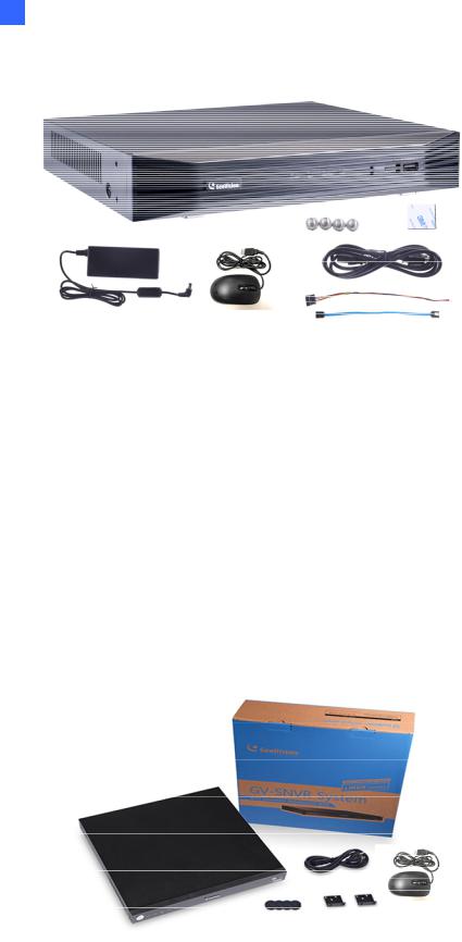
1.3.1 GV-SNVR Single Package GV-SNVR0400F
1. GV-SNVR0400F
2. AC power cord
3. AC/DC adapter
(DC 19V, 3.42A, 65 W) 4. Screw x 6 (for HDD) 5. SATA cable
6. Download Guide
7. Quick Start Guide
8. Warranty card
GV-SNVR0411
1. GV-SNVR0411
2. AC power cord
3. AC/DC adapter
(DC 52V, 1.38 A, 72 W) 4. SATA cable
5. HDD power cable
6. Screw x 4 (for HDD)
7. Rubber foot x 4 (for HDD)
8. USB mouse
9. Download Guide
10. Warranty card
4
GV-SNVR0412
1. GV-SNVR0412
2. AC Power cord
3. AC/DC adapter
(DC 48 V, 1.35 A, 65 W) 4. SATA cable
5. HDD power cable
6. Screw x 4 (for HDD)
7. USB mouse
8. Foam foot
9. Rack mount kit (2 L-shaped brackets + 4 screws)
10. Download Guide
11. Warranty card
GV-SNVR0811
1. GV-SNVR0811
2. AC Power cord
3. AC/DC adapter
(DC 56V, 2.32 A, 130 W) 4. SATA cable
5. HDD power cable
6. Screw x 4 (for HDD)
7. USB mouse
8. Download Guide
9. Warranty card
5
1 Introduction
GV-SNVR0812
1. GV-SNVR0812
2. AC power cord
3. AC/DC adapter (DC 52V, 1.8A, 100W)
4. SATA cable
5. HDD power cable
6. Screw x 4 (for HDD)
7. Foam foot
8. USB mouse
9. Rack mount kit (2 L-shaped brackets + 4 screws)
10. Download Guide
11. Warranty card
GV-SNVR1600
1. GV-SNVR1600
2. AC power cord
3. SATA cable x 4
4. HDD mounting bracket kit (4 pairs and 32 screws included)
5. Rack mount kit (2 L-shaped brackets and 6 screws included)
6. Rubber foot x 4
7. USB mouse
8. Download Guide
9. Quick Start Guide
10. Warranty card
6
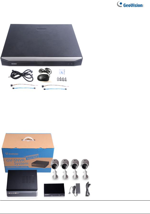
GV-SNVR1611
1. GV-SNVR1611
2. AC power cord
3. SATA cable x 2
4. HDD power cable x 2
5. Screw x 8 (for HDD)
6. Foam foot
7. USB mouse
8. Download Guide
9. Warranty card
1.3.2 GV-SNVR Bundled Package
GV-SNVR0400F
1. GV-SNVR0400F package x 1
2. Target IP Camera x 4
3. GV-POE0400 x 1
Note: For the Target IP Camera, select any 4 models from GV-EBL1100 / 2100, GV-EBX1100 / 2100, GV-EDR1100 / 2100, GV-EFD1100 / 2100. Contact your dealer for more information.
7

1 Introduction
1.4Compatible Products and System Requirements
1.4.1 Supported GV-IP Cameras
The GV-SNVR is compatible with the following GV-IP Cameras:
˙GV-Target Series IP Cameras (Firmware V1.0 or later)
˙GV-SD220/220-S (Firmware V1.04 or later)
˙GV-UNFE2503 / UNP2500 (Firmware V2.11 or later)
˙All other GV-IP Cameras EXCEPT for the models below:
|
GV-SNVR System |
|
|
Not Supported Models |
|
|
|
|
|
|
GV-ABD1300 |
|
|
|
|
GV-ABL Series / ADR Series / AVD Series / EBD Series / TBL |
|
|
|
|
|
|
Series / TDR Series / TVD Series |
|
SNVR0400F |
|
|
|
GV-BX110/12201 |
|
|
|
|
|
GV-BL110 |
|
|
|
|
GV-EBL2101 / 2111 / 3101 (conditionally supported) (*Note4) |
|
|
|
|
|
|
GV-FD8700-FR |
|
|
|
|
|
GV FER12203 / 12700 |
|
|
|
|
GV-Fisheye Cameras (conditionally supported) (*Note3) |
|
|
|
|
|
|
GV-MFD110 |
|
|
|
|
|
GV-PT110 |
|
SNVR1600 |
|
|
|
GV-PTZ010D |
|
|
|
|
GV-SD010 / 200 / 200-S / 2301 / 2322-IR / 2411 / 2722-IR / |
|
|
|
|
|
|
3732-IR |
|
|
|
|
|
GV-VD8700 |
|
|
|
|
|
GV-VR360 |
|
SNVR0411 |
|
|
|
GV-BX110 |
|
|
|
|
|
GV-BL110 |
|
SNVR0412 |
|
|
||
|
|
|
|
GV-FE520 / 521 |
|
|
|
|
|
||
|
|
|
|
|
GV-FER12203 / 12700 |
|
SNVR0811 |
|
|
||
|
|
|
|
GV-MFD110 |
|
|
|
|
|
||
|
SNVR0812 |
|
|
|
GV-PT110 |
|
|
|
|
GV-PTZ010D |
|
|
|
|
|
||
|
|
|
|
||
|
SNVR1611 |
|
|
|
GV-SD010 |
|
|
|
|
|
|
Note: The live view of GV-SD200 / 200-S / 2411 / 2322-IR / 3732-IR can be accessed through GV-SNVR0411 / 0811, but their PTZ control functions are only available on GV-SNVR0411 firmware V2.61 or later and GV-SNVR0811 firmware V2.50 or later.
8
IMPORTANT:
1.GV-SNVR supports a recording frame rate of up to 30 fps.
2.GV-SNVR supports a total bandwidth of up to 50 Mbps for GV-SNVR0400F, 40 Mbps for GV-SNVR0411, 24 Mbps for GV-SNVR0412, 80 Mbps for GV-SNVR0811, 48 Mbps for GV-SNVR0812, 100 Mbps for GV-SNVR1600 and 320 Mbps for GV-SNVR1611.
3.GV-SNVR1600 can only connect to GV-Fisheye Cameras, except for GV-FER12203 / 12700, via channel 1 and does not support fisheye dewarping(*).
4.GV-EBL2101 / 2111 / 3101 is only supported on channel 1 of GV-SNVR0400F (*).
5.For supported IP cameras, the resolutions of stream 1 and 2 both must meet the requirements noted in Appendix C.
1.4.2 Supported GeoVision Applications
GV-SNVR is compatible with the following applications:
For GV-SNVR0411 / 0811
˙GV-Edge Recording Manager (Windows Version V1.2.0.0 or later)
˙GV-Control Center (V3.4.0.0 or later)
˙GV-Center V2 (V15.10 or later)
˙GV-Vital Sign Monitor (V15.10 or later)
˙GV-Eye (V2.3 or later)
˙GV-Cloud Center (V1.0 or later)
For GV-SNVR0412 / 0812
˙GV-Edge Recording Manager (Windows Version V1.4.0 or later)
˙GV-Control Center (V3.6.0 or later)
˙GV-Center V2 (V17.1 or later)
˙GV-Vital Sign Monitor (V17.1 or later)
˙GV-Eye (for iOS / Android V2.7.2 or later)
˙GV-Cloud Center (V1.0 or later)
9

1Introduction
For GV-SNVR1611
˙GV-Center V2 (V16.11 or later)
˙GV-Vital Sign Monitor (V16.11 or later)
˙GV-Eye (V2.5.1 or later)
˙GV-Cloud Center (V1.0 or later)
For GV-SNVR0400F / 1600
˙GV-Edge Recording Manager (Windows Version V1.1.0.0 or later)
˙GV-Control Center (V3.3.0.0 or later)
˙GV-Center V2 (V15.10 or later)
˙GV-Vital Sign Monitor (V15.10 or later)
˙GV-Eye (V2.0 or later)
1.4.3 System Requirements
Recommended Hard Disks
For system efficiency, it is recommended to use enterprise-level hard disk drives instead of desktop-level or green HDD. For tested hard disk drives, see Appendix.
Note: GV-SNVR does not support 2.5” SATA HDD.
Supported Web Browsers
Internet Explorer 8 or later (10 or later for GV-SNVR0412 / 0812)
Google Chrome
Mozilla Firefox
Safari (Only for GV-SNVR0411 / 0412 / 0811 / 0812 / 1611)
Microsoft Edge (Only for GV-SNVR0411 / 0412 / 0811 / 0812 / 1611)
10

1.5Optional Accessories
Optional devices can expand your GV-SNVR’s capabilities and versatility. Contact your dealer for more information.
|
|
|
GV-Joystick V2 facilitates PTZ camera control. It can be plugged |
|
GV-Joystick V2 |
|
into the GV-SNVR for independent use to empower the operation of |
|
|
|
PTZ cameras. |
|
|
|
GV-POE Switch is designed to provide power along with network |
|
GV-POE Switch |
|
connection for IP devices. GV-POE Switch is available in various |
|
|
|
models with different numbers and types of ports. |
|
|
|
For GV-SNVR0411 / 0811 / 1611 only, GV-WiFi Adaptor V2 is |
|
GV-WiFi Adaptor V2 |
|
designed to connect GV-IP devices to a wireless network. This |
|
|
|
product supports 2.4 GHz and 5 GHz wireless connection. |
|
Slide Rail Kit |
|
The Slide Rail Kit is used to mount a rail for the GV-SNVR1600 in a |
|
|
19” cabinet. |
|
|
|
|
|
|
|
|
|
11

1 Introduction
1.6Overview
1.6.1 Front View
1.6.1.1GV-SNVR0411
1 |
3 |
4 |
||||
|
|
2 |
|
|
|
|
|
|
|
|
|
|
|
|
|
Figure 1-2 |
|
|
|
|
|
No. |
Name |
Function |
|
|
|
|
|
1 |
Power LED |
Shows constant green when power is supplied. |
|
|
|
|
|
|
|
Shows constant red when: |
|
2 |
HDD Error LED |
˙ No hard drive is installed. |
|
˙ The hard drive is not formatted. |
|||
|
|
||
|
|
˙ The hard drive fails. |
|
|
|
|
|
3 |
HDD LED |
Blinks green when the HDD is writing or reading data. |
|
|
|
|
|
4 |
USB 2.0 Port |
Connects to a keyboard, mouse, USB flash drive, GV-WiFi Adaptor |
|
V2 or GV-Joystick V2. |
|||
|
|
||
|
|
|
12
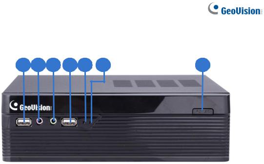
1.6.1.2GV-SNVR0400F
|
|
Figure 1-3 |
|
|
|
|
|
No. |
Name |
Function |
|
|
|
|
|
1 |
USB 2.0 Port |
Connects to a keyboard, mouse, USB flash drive or GV-Joystick V2. |
|
|
|
|
|
2 |
Audio In |
Not functional. |
|
|
|
|
|
3 |
Audio Out |
Connects to a speaker. |
|
|
|
|
|
4 |
Power LED |
Shows constant blue when power is supplied. |
|
|
|
|
|
|
|
Shows constant red when: |
|
5 |
HDD Error LED |
˙ No hard drive is installed. |
|
˙ The hard drive is not formatted. |
|||
|
|
||
|
|
˙ The hard drive fails. |
|
|
|
|
|
6 |
Power Button |
Turns on/off the power. |
|
|
|
|
13
1Introduction
1.6.1.3 GV-SNVR0811
|
|
Figure 1-4 |
|
|
|
|
|
No. |
Name |
Function |
|
|
|
|
|
1 |
Power LED |
Shows constant green when power is supplied. |
|
|
|
|
|
|
|
Shows constant red when: |
|
2 |
HDD Error LED |
˙ No hard drive is installed. |
|
˙ The hard drive is not formatted. |
|||
|
|
||
|
|
˙ The hard drive fails. |
|
|
|
|
|
3 |
HDD LED |
Blinks green when the HDD is writing or reading data. |
|
|
|
|
|
4 |
PoE LED |
Indicates the PoE port in use. |
|
|
|
|
14
1.6.1.4 GV-SNVR1600
2 4 6
1 |
3 |
|
|
|
|
7 |
|||||
|
5 |
||||||||||
|
|
|
|
|
|
|
|
|
|
|
|
|
|
|
|
|
|
|
|
|
|
|
|
|
|
|
|
|
|
|
|
|
|
|
|
|
|
Figure 1-5 |
|
|
|
|
|
No. |
Name |
Function |
|
|
|
|
|
1 |
Power Button |
Turns on/off the power. |
|
|
|
|
|
2 |
Power LED |
Shows constant blue when power is supplied. |
|
|
|
|
|
3 |
HDD Status LED |
Flashes blue when the hard drive is writing or reading data. |
|
|
|
|
|
|
|
Shows constant red when: |
|
4 |
HDD Error LED |
˙ No hard drive is installed. |
|
˙ The hard drive is not formatted. |
|||
|
|
||
|
|
˙ The hard drive fails. |
|
|
|
|
|
5 |
WAN LED |
Flashes blue when the WAN port is receiving activity. |
|
|
|
|
|
6 |
LAN LED |
Flashes blue when the LAN port is receiving activity. |
|
|
|
|
|
7 |
USB 2.0 Port |
Connects to a keyboard, mouse, USB flash drive or GV-Joystick V2. |
|
|
|
|
15

1Introduction
1.6.1.5 GV-SNVR1611
|
|
Figure 1-6 |
|
|
|
|
|
No. |
Name |
Function |
|
|
|
|
|
1 |
HDD1 LED |
Constant blue when HDD1 is writing or reading data. |
|
|
|
|
|
2 |
HDD2 LED |
Constant blue when HDD2 is writing or reading data. |
|
|
|
|
|
|
|
Shows constant red when one or both of the hard drives is: |
|
3 |
HDD Fail LED |
˙ Not formatted. |
|
|
|
˙ Fails to read or write. |
|
|
|
|
|
4 |
Power LED |
Shows constant blue when power is supplied. |
|
|
|
|
|
5 |
USB 2.0 Port |
Connects to a keyboard, mouse, USB flash drive, GV-WiFi Adaptor |
|
V2 or GV-Joystick V2. |
|||
|
|
||
|
|
|
16

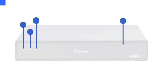
1.6.1.6 GV-SNVR0812
|
|
Figure 1-7 |
|
|
|
No. |
Name |
Function |
|
|
|
1 |
Power LED |
Shows constant blue when power is supplied. |
|
|
|
2 |
Network LED |
Shows constant blue when connected to a network. |
|
|
|
|
|
Shows constant red when the hard drive is either: |
3 |
HDD Fail LED |
˙ Not formatted. |
|
|
˙ Fails to read or write. |
|
|
|
4 |
HDD LED |
Shows constant blue when the hard drive is writing or reading data. |
|
|
|
5 |
USB 2.0 Port |
Connects to a keyboard, mouse, USB flash drive or GV-Joystick V2. |
|
|
|
1.6.1.7 GV-SNVR0412
|
|
Figure 1-8 |
|
|
|
No. |
Name |
Function |
|
|
|
1 |
Power LED |
Shows constant blue when power is supplied. |
|
|
|
2 |
Network LED |
Shows constant blue when connected to a network. |
|
|
Shows constant red when the hard drive is either: |
3 |
HDD Fail LED |
˙ Not formatted. |
|
|
˙ Fails to read or write. |
|
|
|
4 |
HDD LED |
Shows constant blue when the hard drive is writing or reading data. |
|
|
|
5 |
USB 2.0 Port |
Connects to a keyboard, mouse, USB flash drive or GV-Joystick V2. |
|
|
|
|
|
17 |
1 Introduction
1.6.2 Rear View
1.6.2.1 GV-SNVR0411
|
|
|
|
|
|
|
|
|
|
|
|
|
|
|
|
|
|
|
|
|
|
|
|
|
|
|
|
|
|
|
|
|
|
|
|
|
|
|
|
|
|
|
|
|
|
5 |
|
|
|
|
3 |
2 |
1 |
|
|
|
6 |
|
|
4 |
|
|
|
|
|
|
|
Figure 1-9 |
|
|
|
|
|
|
||
|
|
|
|
|
|
|
|
|
|
|
No. |
Name |
Function |
|
|
|
|
|
|
||
|
|
|
|
|
|
|
|
|
|
|
1 |
DC 52 V (Power Input) |
Connects to power supply. |
|
|
||||||
|
|
|
|
|
||||||
2 |
Megabit PoE Ports |
Connects to cameras, delivering power and network |
||||||||
connection to the cameras. |
|
|
||||||||
|
|
|
|
|||||||
|
|
|
|
|
|
|
|
|
|
|
3 |
WAN |
Connects to the network. |
|
|
|
|
|
|
||
|
|
|
|
|
||||||
4 |
USB 2.0 Port |
Connects to a keyboard, mouse, USB flash drive, GV-WiFi |
||||||||
Adaptor V2 or GV-Joystick V2. |
|
|
||||||||
|
|
|
|
|||||||
|
|
|
|
|
||||||
5 |
Default Button |
Restores the device to its default settings. Press the button for |
||||||||
15 seconds to load default. |
|
|
||||||||
|
|
|
|
|||||||
|
|
|
|
|
|
|
|
|
|
|
6 |
HDMI Output |
Connects to a HD TV. |
|
|
|
|
|
|
||
|
|
|
|
|
|
|
|
|
|
|
18

1.6.2.2GV-SNVR0400F
|
|
Figure 1-10 |
|
|
|
|
|
No. |
Name |
Function |
|
|
|
|
|
1 |
Gigabit Ethernet Port |
Connects to the network. |
|
|
|
|
|
2 |
HDMI Output |
Connects to a HD TV. |
|
|
|
|
|
3 |
USB 2.0 Port |
Connects to a keyboard, mouse, USB flash drive or GV-Joystick |
|
V2. |
|||
|
|
||
|
|
|
|
4 |
Default Button |
Restores the device to default settings. Press the button for 15 |
|
seconds to load default. |
|||
|
|
||
|
|
|
|
5 |
Power Input |
Connects to power supply. |
|
|
|
|
19

1Introduction
1.6.2.3 GV-SNVR0811
|
|
Figure 1-11 |
|
|
|
|
|
No. |
Name |
Function |
|
|
|
|
|
1 |
DC 52 V (Power Input) |
Connects to power supply. |
|
|
|
|
|
2 |
Megabit PoE Ports |
Connects to cameras, delivering power and network |
|
connection to the cameras. |
|||
|
|
||
|
|
|
|
3 |
Network |
Connects to the network. The light on the left turns orange |
|
when connecting to Ethernet of 10 /100 Mbps. |
|||
|
|
||
|
|
|
|
4 |
USB 2.0 Port |
Connects to a keyboard, mouse, USB flash drive, GV-WiFi |
|
Adaptor V2 or GV-Joystick V2. |
|||
|
|
||
|
|
|
|
5 |
HDMI Output |
Connects to a HD TV. |
|
|
|
|
|
6 |
Default Button |
Restores the device to its default settings. Press the button for |
|
15 seconds to load default. |
|||
|
|
||
|
|
|
20
1.6.2.4 GV-SNVR1600
|
|
Figure 1-12 |
|
|
|
|
|
No. |
Name |
Function |
|
|
|
|
|
1 |
Audio Microphone In Port |
Not functional. |
|
|
|
|
|
2 |
VGA Monitor Output |
Connects to a VGA monitor. |
|
|
|
|
|
3 |
HDMI Port |
Connects to a HD TV. |
|
|
|
|
|
4 |
USB 2.0 Port x 4 |
Connects to a keyboard, mouse, USB flash drive or |
|
GV-Joystick V2. |
|||
|
|
||
|
|
|
|
5 |
Power Input |
Connects to power supply. |
|
|
|
|
|
6 |
Gigabit Ethernet Port (LAN) |
Connects to the network. |
|
|
|
|
|
7 |
Gigabit Ethernet Port (WAN) |
Connects to the network. |
|
|
|
|
|
8 |
Audio Line Out Port |
Connects to a headphone. |
|
|
|
|
|
9 |
Audio Line Out Port |
Connects to a speaker. |
|
|
|
|
Note: When the two Ethernet ports (No. 6 and No. 7) are used together, one is LAN port and the other is WAN port.
21
1Introduction
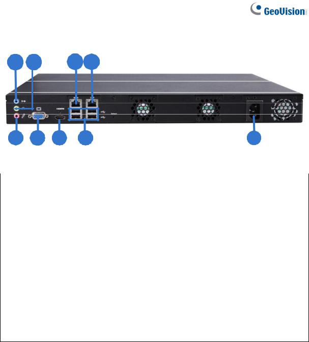
1.6.2.5 GV-SNVR1611
|
|
Figure 1-13 |
|
|
|
|
|
No. |
Name |
Function |
|
|
|
|
|
1 |
Megabit PoE Ports |
Connects to cameras, delivering power and network |
|
connection to the cameras. |
|||
|
|
||
|
|
|
|
2 |
Megabit Ethernet Port (WAN) |
Connects to the network. |
|
|
|
|
|
3 |
Audio Line In Port |
Connects to a microphone. |
|
|
|
|
|
4 |
Audio Line Out Port |
Connects to a speaker. |
|
|
|
|
|
5 |
VGA Output |
Connects to a VGA monitor. |
|
|
|
|
|
6 |
I/O Panel |
Connects to 4 input and 1 output devices |
|
|
|
|
|
7 |
HDMI Output |
Connects to a HD TV. |
|
|
|
|
|
8 |
USB 3.0 Port |
Connects to a keyboard, mouse, USB flash drive or |
|
GV-Joystick V2. |
|||
|
|
||
|
|
|
|
9 |
Power Input |
Connects to power supply. |
|
|
|
|
|
10 |
Power Button |
Turns the system on or off. |
|
|
|
|
Note: GV-SNVR1611 does not have a load default button. To restore factory settings manually, right-click the mouse five times during the startup screen, with the GeoVision logo, or see 6.2.5 Restoring to Factory Default Settings for loading default via GV-IP Device Utility.
22

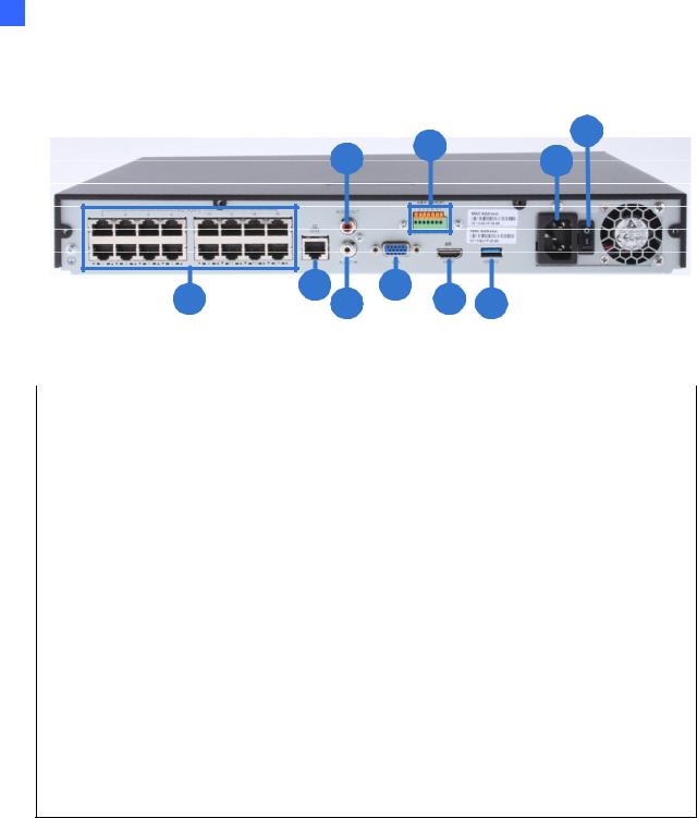
1.6.2.6 GV-SNVR0812
|
|
Figure 1-14 |
|
|
|
|
|
No. |
Name |
Function |
|
|
|
|
|
1 |
I/O Panel |
Connects to 4 input and 1 output devices |
|
|
|
|
|
2 |
Audio Line Out Port |
Connects to a speaker. |
|
|
|
|
|
3 |
Audio Line In Port |
Connects to a microphone. |
|
|
|
|
|
4 |
HDMI Output |
Connects to a HD TV. |
|
|
|
|
|
5 |
VGA Output |
Connects to a VGA monitor. |
|
|
|
|
|
6 |
USB 2.0 Port |
Connects to a keyboard, mouse, USB flash drive or |
|
GV-Joystick V2. |
|||
|
|
||
|
|
|
|
7 |
Megabit PoE Ports |
Connects to cameras, delivering power and network |
|
connection to the cameras. |
|||
|
|
||
|
|
|
|
|
|
Connects to the network. The light at the bottom |
|
8 |
Megabit Ethernet Port (WAN) |
flashes green when connecting to Ethernet of 10 |
|
|
|
/100 Mbps. |
|
|
|
|
|
9 |
DC 52 V (Power Input) |
Connects to power supply. |
|
|
|
|
IMPORTANT: Only connect GV-SNVR0812 to the Internet through its WAN Port (No. 8, Figure 1-14) as opposed to any of the 8 PoE ports (No. 7, Figure 1-14), as they are only for connecting to IP devices and have limited network connection.
Note:
1. IP devices connected to the PoE ports are provided network connection via an isolated network that is not bridged to, or inaccessible by, the WAN.
2. IP devices connected to the PoE ports are assigned a channel number in accordance to the PoE port number.
3. GV-SNVR0812 does not have a load default button. To restore factory default settings through its UI or GV-IP Device Utility, see 3.8 System or 6.2.5 Restoring to Factory Default Settings, respectively.
23

1Introduction
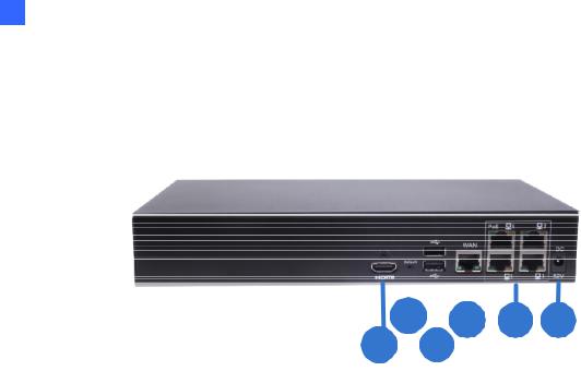
1.6.2.7 GV-SNVR0412
|
|
Figure 1-15 |
|
|
|
|
|
No. |
Name |
Function |
|
|
|
|
|
1 |
I/O Panel |
Connects to 4 input and 1 output devices |
|
|
|
|
|
2 |
Audio Line Out Port |
Connects to a speaker. |
|
|
|
|
|
3 |
Audio Line In Port |
Connects to a microphone. |
|
|
|
|
|
4 |
HDMI Output |
Connects to a HD TV. |
|
|
|
|
|
5 |
VGA Output |
Connects to a VGA monitor. |
|
|
|
|
|
6 |
USB 2.0 Port |
Connects to a keyboard, mouse, USB flash drive or |
|
GV-Joystick V2. |
|||
|
|
||
|
|
|
|
7 |
Megabit PoE Ports |
Connects to cameras, delivering power and network |
|
connection to the cameras. |
|||
|
|
||
|
|
|
|
|
|
Connects to the network. The light at the bottom |
|
8 |
Megabit Ethernet Port (WAN) |
flashes green when connecting to Ethernet of 10 |
|
|
|
/100 Mbps. |
|
|
|
|
|
9 |
DC 52 V (Power Input) |
Connects to power supply. |
|
|
|
|
IMPORTANT: Only connect GV-SNVR0412 to the Internet through its WAN Port (No. 8, Figure 1-15) as opposed to any of the 4 PoE ports (No. 7, Figure 1-15), as they are only for connecting to IP devices and have limited network connection.
Note:
1. IP devices connected to the PoE ports are provided network connection via an isolated network that is not bridged to, or inaccessible by, the WAN.
2. IP devices connected to the PoE ports are assigned a channel number in accordance to the PoE port number.
3. GV-SNVR0412 does not have a load default button. To restore factory default settings through its UI or GV-IP Device Utility, see 3.8 System or 6.2.5 Restoring to Factory Default Settings, respectively.
24
Loading...