


Quick Start Guide
GV-IP Camera H.264
Before attempting to connect or operate this product,
please read these instructions carefully and save this manual for future use.

© 2012 GeoVision, Inc. All rights reserved.
Under the copyright laws, this manual may not be copied, in whole or in part, without the written consent of GeoVision.
Every effort has been made to ensure that the information in this manual is accurate. GeoVision, Inc. makes no expressed or implied warranty of any kind and assumes no responsibility for errors or omissions. No liability is assumed for incidental or consequential damages arising from the use of the information or products contained herein. Features and specifications are subject to change without notice. Note: no memory card slot or local storage function for Argentina.
GeoVision, Inc.
9F, No. 246, Sec. 1, Neihu Rd., Neihu District, Taipei, Taiwan Tel: +886-2-8797-8377
Fax: +886-2-8797-8335 http://www.geovision.com.tw
Trademarks used in this manual: GeoVision, the GeoVision logo and GV series products are trademarks of GeoVision, Inc. Windows and Windows XP are registered trademarks of Microsoft Corporation.
August 2012
Safety Notice
For GV-CBW120 and GV-CBW220:
This device complies with Part 15 of the FCC Rules. Operation is subject to the following two conditions: (1) this device may not cause harmful interference and (2) this device must accept any interference received, including interference that may cause undesired operation of the device.
UL Certification for GV-MFD120/130/220/320/520
The GV-IPCAM H.264 uses a 3.0V CR2032 Lithium battery as the power supply for its internal real-time clock (RTC). The battery should not be replaced unless required!
If the battery does need replacing, please observe the following:
•Danger of Explosion if battery is incorrectly replaced
•Replace only with the same or equivalent battery, as recommended by the manufacturer
•Dispose of used batteries according to the manufacturer's instructions
i

|
Contents |
|
Introduction ................................................................................ |
vii |
|
Options |
...................................................................................... |
xiii |
Note for Connecting to GV-System .......................................... |
xv |
|
Note for Adjusting Focus and Zoom ....................................... |
xvi |
|
Note for Installing Camera Outdoor ....................................... |
xvii |
|
1. Box Camera .............................................................................. |
1 |
|
1.1 |
Packing List............................................................................... |
1 |
1.2 |
Overview ................................................................................... |
2 |
|
GV-BX110D ............................................................................... |
2 |
|
GV-BX120D / 130D Series / 140DW / 220D Series / 320D Series / |
|
|
520D-0 ..................................................................................... |
4 |
|
GV-BX1200 Series / 1300 Series / 2400 Series / 3400 Series / |
|
|
5300-6V…..................................................................................6 |
|
1.3 |
Accessory Installation................................................................ |
8 |
1.3.1 C-Mount Lenses ..................................................................... |
8 |
|
1.3.2 Infrared Illuminators (GV-IR LED / GV-IR LED T2)................ |
10 |
|
1.4 |
Connecting the Camera........................................................... |
12 |
|
GV-BX110D ............................................................................. |
12 |
|
GV-BX120D / 130D Series / 140DW / 220D Series / 320D Series / |
|
|
520D-0 ................................................................................... |
14 |
|
GV-BX1200 Series / 1300 Series / 2400 Series / 3400 Series / |
|
|
5300-6V…………………………………….…………………………16 |
|
2. IR Arctic Box Camera ............................................................ |
19 |
|
2.1 |
Packing List............................................................................. |
19 |
2.2 |
Overview ................................................................................. |
20 |
2.3 |
Installation ............................................................................... |
21 |
2.4 |
Connecting the Camera........................................................... |
25 |
|
2.4.1 Wire Definition ................................................................. |
25 |
3. Mini Fixed Dome & Mini Fixed Rugged Dome ..................... |
27 |
|
3.1 |
Packing List............................................................................. |
27 |
3.2 |
Overview ................................................................................. |
28 |
|
GV-MFD110............................................................................. |
28 |
|
GV-MFD120 / 130 / 220 / 320 / 520 .......................................... |
29 |
ii |
|
|
|
LED Indicator ........................................................................... |
30 |
|
GV-MDR120 / 220 / 320 / 520 .................................................. |
30 |
3.3 |
Installation ............................................................................... |
32 |
|
GV-MFD Series........................................................................ |
32 |
|
GV-MDR Series ....................................................................... |
34 |
3.4 |
Connecting the Camera........................................................... |
38 |
|
3.4.1 Wire Definition ................................................................. |
38 |
|
3.4.2 Power and Network Connection....................................... |
39 |
|
3.4.3 Vehicle Installation........................................................... |
40 |
4. Bullet Camera......................................................................... |
41 |
|
4.1 |
Packing List............................................................................. |
41 |
4.2 |
Overview ................................................................................. |
42 |
4.3 |
Installation ............................................................................... |
43 |
|
4.3.1 Adjusting the Angles........................................................ |
44 |
|
4.3.2 Adjusting Lens and Inserting a Memory Card................... |
47 |
|
4.3.3 Inserting the Sun-Shield Cover ........................................ |
49 |
4.4 |
Connecting the Camera........................................................... |
50 |
|
4.4.1 Wire Definition ................................................................. |
50 |
|
4.4.2 Connecting the Power Cable ........................................... |
51 |
5. Vandal Proof IP Dome............................................................ |
53 |
|
5.1 |
Packing List............................................................................. |
53 |
5.2 |
Overview ................................................................................. |
55 |
5.3 |
Installation ............................................................................... |
56 |
|
5.3.1 Hard-Ceiling Mount.......................................................... |
56 |
|
5.3.2 In-Ceiling Mount .............................................................. |
61 |
5.4 |
Connecting the Camera........................................................... |
64 |
|
5.4.1 Wire Definition ................................................................. |
64 |
|
5.4.2 Connecting the Power Cable ........................................... |
65 |
6. Fixed IP Dome ........................................................................ |
67 |
|
6.1 |
Packing List............................................................................. |
67 |
|
6.1.1 Packing List for Hard-Ceiling Mount................................. |
67 |
|
6.1.2 Packing List for In-Ceiling Mount...................................... |
68 |
6.2 |
Overview ................................................................................. |
69 |
6.3 |
Installation ............................................................................... |
71 |
|
6.3.1 Hard-Ceiling Mount.......................................................... |
71 |
|
|
iii |

|
6.3.2 In-Ceiling Mount .............................................................. |
75 |
|
6.3.3 Wall-Surface Mount ......................................................... |
78 |
6.4 |
Connecting the Camera........................................................... |
80 |
7. Cube Camera.......................................................................... |
81 |
|
7.1 |
Packing List............................................................................. |
81 |
7.2 |
Overview ................................................................................. |
82 |
7.3 |
Installation ............................................................................... |
83 |
7.4 |
Connecting the Camera........................................................... |
85 |
8. Advanced Cube Camera........................................................ |
87 |
|
8.1 |
Packing List............................................................................. |
87 |
8.2 |
Overview ................................................................................. |
88 |
8.3 |
Installation ............................................................................... |
90 |
8.4 |
Connecting the Camera........................................................... |
92 |
9. Accessing the Camera........................................................... |
93 |
|
9.1 |
System Requirement ............................................................... |
93 |
9.2 |
Accessing the Live View.......................................................... |
94 |
|
9.2.1 Checking the Dynamic IP Address................................... |
95 |
|
9.2.2 Configuring the IP Address .............................................. |
97 |
|
9.2.3 Configuring the Wireless Connection ............................... |
99 |
9.3 |
Adjusting Image Clarity.......................................................... |
102 |
|
9.3.1 Using Focus Adjustment Cap......................................... |
104 |
10. The Web Interface .............................................................. |
107 |
|
11. Upgrading System Firmware............................................. |
109 |
|
12. Restoring to Default Settings............................................ |
111 |
|
12.1 Using the Web Interface ...................................................... |
111 |
|
12.2 Directly on the Camera........................................................ |
112 |
|
|
GV-BX110D ........................................................................... |
112 |
|
Box Camera (except GV-BX110D) ......................................... |
113 |
|
GV-MFD110........................................................................... |
114 |
|
GV-MFD120 / 130 / 220 / 320 / 520 ........................................ |
114 |
|
Mini Fixed Rugged Dome ....................................................... |
115 |
|
GV-BL110D............................................................................ |
115 |
|
GV-BL120D / 130D / 220D / 320D .......................................... |
116 |
|
Vandal Proof IP Dome............................................................ |
116 |
|
Fixed IP Dome ....................................................................... |
117 |
iv |
|
|
Cube Camera......................................................................... |
117 |
Advanced Cube Camera ........................................................ |
118 |
v

vi
Introduction
Welcome to the GV-IPCam H.264 Quick Start Guide. In this quick guide, you will find information on the installation and basic configurations of the
Box Camera, IR Arctic Box Camera, Mini Fixed Dome, Mini Fixed Rugged Dome, Bullet Camera, Vandal Proof IP Dome, Fixed IP Dome, Cube Camera and Advanced Cube Camera.
|
Camera |
|
Model No. |
|
|
Description |
|
|
|
|
Fixed |
|
1.3 MP H.264, D/N, |
|
|
|
GV-BX110D |
Lens |
|
Fixed Iris |
|
|
|
Varifocal |
|
1.3 MP H.264, D/N, |
|
|
|
|
|
|
||
|
|
|
|
Lens |
|
Auto Iris |
|
|
|
|
|
|
1.3 MP H.264, Low |
|
|
|
GV-BX120D |
Varifocal |
|
Lux, D/N, Auto Iris, f: |
|
|
|
Lens |
|
2.8 ~ 12 mm, F/1.4, |
|
|
|
|
|
|
||
|
|
|
|
|
|
1/3’’ CS Lens |
|
|
|
|
|
|
1.3 MP H.264, D/N, |
|
|
|
GV-BX130D-0 |
Varifocal |
|
Auto Iris, |
|
|
|
Lens |
|
f: 2.8 ~ 12 mm, F/1.4, |
|
|
|
|
|
|
||
|
Box |
|
|
|
|
1/3’’ CS Lens |
|
Camera |
|
|
|
|
1.3 MP H.264, D/N, |
|
|
|
GV-BX130D-1 |
Fixed |
|
Fixed Iris, |
|
|
|
Lens |
|
f: 4 mm, F/1.5, |
|
|
|
|
|
|
||
|
|
|
|
|
|
1/3’’ CS Lens |
|
|
|
|
|
|
1 MP H.264, D/N |
|
|
|
GV-BX140DW |
|
|
WDR Pro, Fixed Iris, |
|
|
|
|
|
f: 2.8 ~ 12 mm, |
|
|
|
|
|
Varifocal |
|
|
|
|
|
|
|
F/1.4, 1/3’’ CS Lens |
|
|
|
|
|
Lens |
|
2 MP, H.264 D/N, |
|
|
|
GV-BX220D-2 |
|
|
Auto Iris, f: 2.8 ~ 6 |
|
|
|
|
|
mm, F/1.3, |
|
|
|
|
|
|
|
|
|
|
|
|
|
|
1/3’’ CS Lens |
vii

|
Camera |
|
|
Model No. |
|
|
Description |
|
|
|
|
|
|
|
2 MP, H.264 D/N, |
|
|
|
|
GV-BX220D-3 |
|
|
Auto Iris, f: 2.8 ~ 12 |
|
|
|
|
|
|
mm, F/1.4, |
|
|
|
|
|
|
|
|
|
|
|
|
|
|
|
|
1/3’’ CS Lens |
|
|
|
|
|
|
|
3 MP, H.264 D/N, |
|
|
|
|
GV-BX320D-0 |
|
|
Auto Iris, f: 3.1 ~ 8 |
|
|
|
|
|
|
mm, F/1.2, |
|
|
|
|
|
|
|
|
|
|
|
|
|
|
Varifocal |
|
1/3’’ CS Lens |
|
|
|
|
|
|
|
|
|
|
|
|
|
Lens |
|
3 MP, H.264 D/N, |
|
|
|
|
GV-BX320D-1 |
|
|
Auto Iris, f: 2.8 ~ 6 |
|
|
|
|
|
|
mm, F/1.3, |
|
|
|
|
|
|
|
|
|
|
|
|
|
|
|
|
1/3’’ CS Lens |
|
|
|
|
|
|
|
|
|
|
|
|
|
|
|
5 MP, H.264 D/N, |
|
|
|
|
GV-BX520D-0 |
|
|
Manual Iris, |
|
|
|
|
|
|
f: 4.5 ~ 10 mm, F/1.6, |
|
|
Box |
|
|
|
|
|
|
|
|
|
|
|
1/2’’ CS Lens |
||
|
Camera |
|
|
|
|
|
|
|
|
GV-BX1200-0F |
|
|
1.3 or 2 MP, H.264 |
||
|
|
|
|
|
|
||
|
|
|
|
|
|
D/N, Fixed Iris, |
|
|
|
|
|
GV-BX1300-0F |
|
|
f: 4 mm, F/1.5, 1/3’’ |
|
|
|
|
|
|
|
CS Lens |
|
|
|
|
GV-BX1200-1F |
|
|
1.3 or 2 MP, H.264 |
|
|
|
|
GV-BX1200-2F |
|
|
D/N, Fixed Iris, |
|
|
|
|
GV-BX1300-1F |
|
|
f: 8 / 12 mm, F/1.6, |
|
|
|
|
GV-BX1300-2F |
Fixed |
|
1/2.5’’ CS Lens |
|
|
|
|
GV-BX2400-0F |
Lens |
|
2 / 3 MP, H.264 D/N, |
|
|
|
|
|
|
WDR Pro, Fixed Iris, |
|
|
|
|
|
GV-BX3400-0F |
|
|
f: 4 mm, F/1.5, 1/3’’ |
|
|
|
|
|
|
|
CS Lens |
|
|
|
|
GV-BX2400-1F |
|
|
2 / 3 MP, H.264 D/N, |
|
|
|
|
GV-BX2400-2F |
|
|
WDR Pro, Fixed Iris, |
|
|
|
|
GV-BX3400-1F |
|
|
f: 8 / 12 mm, F/1.6, |
|
|
|
|
GV-BX3400-2F |
|
|
1/2.5’’ CS Lens |
viii
|
Camera |
|
|
Model No. |
|
|
Description |
|
|
|
|
GV-BX1200-3V |
|
|
1.3 MP, H.264 D/N, |
|
|
|
|
|
|
Auto Iris, f:2.8 ~ 12 |
|
|
|
|
|
|
|
|
|
|
|
|
|
GV-BX1300-3V |
|
|
mm, F/1.4, 1/3” CS |
|
|
|
|
|
|
Lens |
|
|
|
|
|
|
|
|
|
|
|
|
|
|
|
|
2 MP, H.264 D/N, |
|
|
|
|
GV-BX2400-3V |
|
|
WDR Pro, Auto Iris, |
|
|
|
|
|
|
f:2.8 ~ 12 mm, F/1.4, |
|
|
|
|
|
|
|
|
|
|
|
|
|
|
|
|
1/3” CS Lens |
|
|
|
|
GV-BX2400-4V |
|
|
2 / 3 MP, H.264 D/N, |
|
Box |
|
|
Varifocal |
|
WDR Pro, Auto Iris, |
|
|
|
|
GV-BX3400-4V |
|
f:3 ~ 10.5 mm, F/1.4, |
||
|
Camera |
|
|
Lens |
|
||
|
|
|
|
|
1/2.7” CS Lens |
||
|
|
|
|
|
|
|
|
|
|
|
|
|
|
|
3 MP, H.264 D/N, |
|
|
|
|
GV-BX3400-5V |
|
|
WDR Pro, Auto Iris, |
|
|
|
|
|
|
f: 2.8 ~ 6 mm, F/1.3, |
|
|
|
|
|
|
|
|
|
|
|
|
|
|
|
|
1/3’’ CS Lens |
|
|
|
|
|
|
|
5 MP, H.264 D/N, |
|
|
|
|
GV-BX5300-6V |
|
|
Manual Iris, |
|
|
|
|
|
|
f: 4.5 ~ 10 mm, F/1.6, |
|
|
|
|
|
|
|
|
|
|
|
|
|
|
|
|
1/2’’ CS Lens |
|
|
|
|
|
|
|
1.3 MP, H.264, Low |
|
|
|
|
GV-BX120D-E |
|
|
Lux, D/N, Auto Iris, f: |
|
|
|
|
|
|
2.8 ~ 12 mm, F/1.4, |
|
|
|
|
|
|
|
|
|
|
|
|
|
|
|
|
1/3’’ CS Lens |
|
|
|
|
|
|
|
2 MP, H.264 D/N, |
|
|
|
|
GV-BX220D-E |
|
|
Auto Iris, f: 2.8 ~ 6 |
|
IR |
|
|
|
|
mm, F/1.3, 1/3’’ CS |
|
|
|
|
|
|
|
||
|
Arctic |
|
|
|
Varifocal |
|
Lens |
|
Box |
|
|
|
Lens |
|
3 MP, H.264 D/N, |
|
Camera |
|
|
GV-BX320D-E |
|
|
Auto Iris, f: 2.8 ~ 6 |
|
|
|
|
|
|
mm, F/1.3, 1/3’’ CS |
|
|
|
|
|
|
|
|
|
|
|
|
|
|
|
|
Lens |
|
|
|
|
|
|
|
5 MP, H.264 D/N, |
|
|
|
|
GV-BX520D-E |
|
|
Manual Iris, f: 4.5 ~ |
|
|
|
|
|
|
10 mm, F/1.6, 1/3’’ |
|
|
|
|
|
|
|
|
|
|
|
|
|
|
|
|
CS Lens |
|
|
|
|
|
|
|
ix |

|
Camera |
|
|
Model No. |
|
|
Description |
|
|
|
|
GV-MFD110 |
|
|
1.3 MP H.264, Color, |
|
|
|
|
|
|
Fixed Iris |
|
|
|
|
|
|
|
|
|
|
|
|
|
GV-MFD120 |
|
|
1.3 MP, H.264, Low |
|
|
|
|
|
|
Lux Color, Fixed Iris |
|
|
|
|
|
|
|
|
|
|
Mini |
|
|
GV-MFD130 |
|
|
1.3 MP, H.264, Color, |
|
|
|
Fixed |
|
Fixed Iris |
||
|
Fixed |
|
|
|
|
||
|
|
|
|
Lens |
|
2 MP, H.264, Color, |
|
|
Dome |
|
|
GV-MFD220 |
|
||
|
|
|
|
|
Fixed Iris |
||
|
|
|
|
|
|
|
|
|
|
|
|
GV-MFD320 |
|
|
3 MP, H.264, Color, |
|
|
|
|
|
|
Fixed Iris |
|
|
|
|
|
|
|
|
|
|
|
|
|
GV-MFD520 |
|
|
5 MP, H.264, Color, |
|
|
|
|
|
|
Fixed Iris |
|
|
|
|
|
|
|
|
|
|
|
|
|
GV-MDR120 |
|
|
1.3 MP Low Lux |
|
|
|
|
|
|
H.264, Color, Fixed |
|
|
Mini |
|
|
|
|
|
Iris |
|
|
|
|
Fixed |
|
2 MP H.264, Color, |
|
|
Fixed |
|
|
GV-MDR220 |
|
||
|
|
|
|
Fixed Iris |
|||
|
Rugged |
|
|
|
Lens |
|
|
|
|
|
|
|
3 MP H.264, Color, |
||
|
Dome |
|
|
GV-MDR320 |
|
|
|
|
|
|
|
|
|
Fixed Iris |
|
|
|
|
|
|
|
|
|
|
|
|
|
GV-MDR520 |
|
|
5 MP H.264, Color, |
|
|
|
|
|
|
Fixed Iris |
|
|
|
|
|
|
|
|
|
|
|
|
|
GV-BL110D |
|
|
1.3 MP H.264, Auto |
|
|
|
|
|
|
Iris |
|
|
|
|
|
|
|
|
|
|
|
|
|
GV-BL120D |
|
|
1.3 MP H.264, |
|
Bullet |
|
|
Varifocal |
|
Low Lux, Auto Iris |
|
|
|
|
|
|
|||
|
|
|
|
|
1.3 MP H.264, Auto |
||
|
Camera |
|
|
GV-BL130D |
Lens |
|
|
|
|
|
|
|
|
Iris |
|
|
|
|
|
|
|
|
|
|
|
|
|
GV-BL220D |
|
|
2 MP H.264, Auto Iris |
|
|
|
|
GV-BL320D |
|
|
3 MP H.264, Auto Iris |
x
|
Camera |
|
|
Model No. |
|
|
Description |
|
|
|
|
GV-VD120D |
|
|
|
|
|
|
|
(IK10+, Transparent Cover) |
|
|
|
|
|
|
|
GV-VD121D |
|
|
1.3 MP H.264, |
|
|
|
|
(IK10+, Smoked Cover) |
|
|
|
|
|
|
|
GV-VD122D |
|
|
Low Lux, Auto Iris |
|
|
|
|
|
|
|
|
|
|
|
|
(IK7, Transparent Cover) |
|
|
|
|
|
|
|
GV-VD123D |
|
|
|
|
|
|
|
(IK7, Smoked Cover) |
|
|
|
|
|
|
|
GV-VD220D |
|
|
|
|
|
|
|
(IK10+, Transparent Cover) |
|
|
|
|
Vandal |
|
|
GV-VD221D |
Varifocal |
|
|
|
Proof IP |
|
|
(IK10+, Smoked Cover) |
Lens |
|
2 MP H.264, Auto Iris |
|
Dome |
|
|
GV-VD222D |
|
|
|
|
|
|
|
|
|
||
|
|
|
|
(IK7, Transparent Cover) |
|
|
|
|
|
|
|
GV-VD223D |
|
|
|
|
|
|
|
(IK7, Smoked Cover) |
|
|
|
|
|
|
|
GV-VD320D |
|
|
|
|
|
|
|
(IK10+, Transparent Cover) |
|
|
|
|
|
|
|
GV-VD321D |
|
|
|
|
|
|
|
(IK10+, Smoked Cover) |
|
|
3 MP H.264, Auto Iris |
|
|
|
|
GV-VD322D |
|
|
|
|
|
|
|
|
|
|
|
|
|
|
|
(IK7, Transparent Cover) |
|
|
|
|
|
|
|
GV-VD323D |
|
|
|
|
|
|
|
(IK7, Smoked Cover) |
|
|
|
|
|
|
|
GV-FD120D |
|
|
1.3 MP H.264, |
|
|
|
|
|
|
Low Lux, Auto Iris |
|
|
|
|
|
|
|
|
|
|
Fixed IP |
|
|
GV-FD220D |
Varifocal |
|
2 MP H.264, |
|
Dome |
|
|
Lens |
|
Auto Iris |
|
|
|
|
|
|
|||
|
|
|
|
GV-FD320D |
|
|
3 MP H.264, |
|
|
|
|
|
|
Auto Iris |
|
|
|
|
|
|
|
|
xi

|
Camera |
|
|
Model No. |
|
|
Description |
|
|
|
|
GV-CB120 |
|
|
1.3 MP H.264, |
|
|
|
|
|
|
Fixed Iris |
|
|
|
|
|
|
|
|
|
|
|
|
|
GV-CB220 |
|
|
2 MP H.264, |
|
Cube |
|
|
Fixed |
|
Fixed Iris |
|
|
|
|
|
|
|||
|
Camera |
|
|
GV-CBW120 |
Lens |
|
1.3 MP H.264, |
|
|
|
|
|
|
Wireless Fixed Iris |
|
|
|
|
|
|
|
|
|
|
|
|
|
GV-CBW220 |
|
|
2 MP H.264, |
|
|
|
|
|
|
Wireless Fixed Iris |
|
|
|
|
|
|
|
|
|
|
|
|
|
GV-CA120 |
|
|
1.3 MP H.264, |
|
|
|
|
|
|
Fixed Iris |
|
|
|
|
|
|
|
|
|
|
Advanced |
|
|
GV-CA220 |
|
|
2 MP H.264, |
|
|
|
Fixed |
|
Fixed Iris |
||
|
Cube |
|
|
|
|
||
|
Camera |
|
|
GV-CAW120 |
Lens |
|
1.3 MP H.264, |
|
|
|
|
|
|
Wireless Fixed Iris |
|
|
|
|
|
|
|
|
|
|
|
|
|
GV-CAW220 |
|
|
2 MP H.264, |
|
|
|
|
|
|
Wireless Fixed Iris |
|
|
|
|
|
|
|
|
For a detailed user’s manual, see GV-IPCam H.264 User’s Manual on the Software DVD.
xii

Options
Optional devices can expand your camera’s capabilities and versatility. Contact your dealer for more information.
Device
GV-IR LED
GV-PA191 PoE
Adapter
GV-Mount
Accessories
GV-WiFi Adapter
Fixed Lens 4 mm
Description
A mountable infrared LED device that improves image performance of Box Cameras under low light conditions. Note that the GV-IR LED is only compatible with GV-BX110D and GV-IR LED T2 is compatible with Box Camera (except GV-BX110D).
The GV-PA191 PoE adapter is designed to provide power and network connection to the cameras over a single Ethernet cable.
The GV-Mount Accessories provide a comprehensive lineup of accessories for installation on ceiling, wall corner and pole. For details, see GV-Mount Accessories Installation Guide on the Software DVD.
The GV-WiFi Adapter is a plug-and-play device designed to connect GV-BX1200 Series / 1300 Series / 2400 Series / 3400 Series / 5300-6V to wireless network. This product complies with IEEE 802.11 b/g/n (Draft 3.0) standards for wireless networking.
The fixed Lens, with focal length 4 mm, F/1.5, 1/3’’ CS Lens, is compatible with GV-BX1200 series / 1300 series / 2400 series / 3400 series.
xiii
Device
Fixed Lens 8 mm
Fixed Lens 12 mm
Varifocal Lens 2.8 ~ 12 mm
Varifocal Lens 3 ~ 10.5 mm
Varifocal Lens 2.8 ~ 6 mm
Smoked Cover
xiv
Description
The fixed Lens, with focal length 8 mm, F/1.6, 1/2.5’’ CS Lens, is compatible with GV-BX1200 series / 1300 series / 2400 series / 3400 series.
The fixed Lens, with focal length 12 mm, F/1.6, 1/2.5’’ CS Lens, is compatible with GV-BX1200 series / 1300 series / 2400 series / BX3400 series.
The varifocal Lens, with focal length 2.8 ~ 12 mm, F/1.4, 1/3’’ CS Lens, is compatible with GV-BX1200 series / 1300 series / 2400 series / 3400 series.
The varifocal Lens, with focal length 3 ~ 10.5 mm, F/1.4, 1/2.7’’ CS Lens, is compatible with GV-2400 series / 3400 series.
The varifocal Lens, with focal length 2.8 ~ 6 mm mm, F/1.3, 1/3’’ CS Lens, is compatible with GV-BX3400 series.
The smoked cover is an IK7, tinted camera cover designed for GV-Fixed IP Dome to conceal the direction of the camera lens.
Note for Connecting to GV-System
The GV-IPCAM H.264 is designed to work with GV-System, a hybrid or digital video management system. Note the following when GV-IPCAM H.264 is connected to GV-System:
1.By default, the images are recorded to the memory card inserted in the
Box Camera, Mini Fixed Dome (except GV-MFD110), Mini Fixed Rugged Dome, Bullet Camera, Vandal Proof IP Dome, Fixed IP Dome, Cube Camera and Advanced Cube Camera. Once the camera is connected to GV-System for video management or the camera’s Live View is accessed through the Web browser (see 9. Accessing the Camera in the Quick Start Guide), the recording to the memory card will be stopped and the recording will be taken control by GV-System. The recording to the memory card will only be resumed when the connection between the camera and GV-System is interrupted. To continue recording when the live view is accessed or when the camera is connected to GV-System, enable the Record to the local storage when live view is accessed option on Video Setting’s page. For detail, see Video Settings section, Administrator Mode Chapter, GV-IPCam H.264 User’s Manual on the Software DVD.
2.Once the camera is connected to GV-System, the resolution set on GV-System will override the resolution set on the camera’s Web interface. You can only change the resolution settings through the Web interface when the connection to GV-System is interrupted.
xv
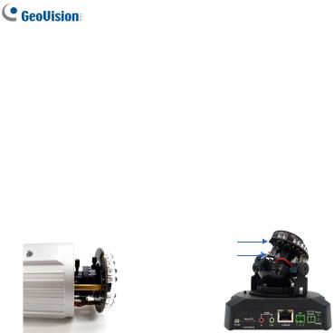
Note for Adjusting Focus and Zoom
When adjusting the Focus and Zoom Screws (on Box Camera, IR Arctic Box Camera, Mini Fixed Dome, Bullet Camera, Vandal Proof IP Dome and Fixed IP Camera), please do not over tighten the Focus and Zoom screws. The screws only need to be as tight as your finger can do it; don't bother using any tools to get them tighter. Doing so can damage the structure of lens.
For example,
|
|
|
Zoom Screw |
Focus Screw |
|
|
|
||
|
|
|
|
Zoom Screw |
|
|
|
Focus Screw |
|
|
|
|
|
Bullet Camera |
Fixed IP Camera |
The maximum torque value for all the zoom and focus screws is 0.049 N.m
xvi
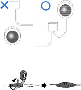
Note for Installing Camera Outdoor
When installing the IR Arctic Box Camera, Bullet Camera, Vandal Proof IP Dome or Mini Fixed Rugged Dome outdoor, be sure that:
1.The camera is set up above the junction box to prevent water from entering the camera along the cables.
2.Any PoE, power, audio and I/O cables are waterproofed using waterproof silicon rubber or the like.
xvii

3.After opening the camera cover, ensure the screws are tightened and the cover is in place.
4.To prevent the lens from fogging up, ensure to replace the silica gel bag every time you open the camera, and conceal the gel bag in camera within 2 minutes of exposing to open air. The silica gel bag loses it effectiveness when the dry camera is opened.
xviii
1. Box Camera
1.1 Packing List
•Box Camera
•Terminal Block
•Fixed Focal or Varifocal Megapixel Lens
•Pin Wrench (for GV-BX110D only)
•C-mount Lens Adapter (for GV-BX110D only)
•Six Lens Rings (not available for GV-BX110D)
•One Lens Ring (for GV-BX140DW only)
•Video Out Wire (not available for GV-BX110D)
•DC 12V Power Adapter
•Camer Holder
•GV-IPCAM H.264 Software DVD
•GV-IPCAM H.264 Quick Start Guide
•GV-NVR Software DVD
•GV-NVR Quick Start Guide
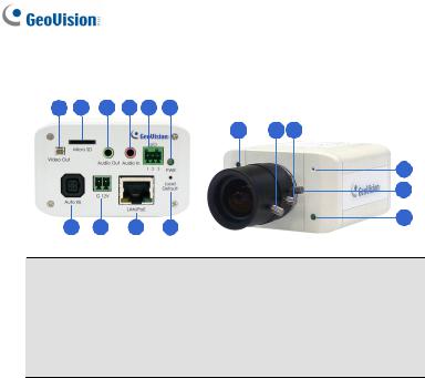
1.2 Overview
GV-BX110D
1 2 3 4 5
9 10
12
6 |
7 |
8 |
11 |
|
13
Note: The Zoom Screw and Auto Iris Connector are only available in the varifocal model.
2
|
|
|
|
|
1 |
Box Camera |
|
|
|
|
|
|
|
||
No. |
|
Name |
|
Description |
|
||
1 |
|
Audio Out |
Connects a speaker for audio output. |
|
|||
2 |
|
Audio In |
|
Connects a microphone for audio input. |
|
||
|
|
|
|
Resets all configurations to factory default. |
|||
3 |
|
Default |
|
See 12. Restoring to Default Settings later |
|||
|
|
|
|
in the Quick Start Guide. |
|
||
4 |
|
Memory Card Slot |
|
Inserts a micro SD/SDHC card to store |
|||
|
|
recording data. |
|
||||
|
|
|
|
||||
|
|
|
|
Connects to a portable monitor for setting |
|||
5 |
|
Video Out |
|
the focus and angle of Box Camera during |
|||
|
|
|
|
initial installation. |
|
||
|
|
|
|
Connects to I/O devices. For details, see |
|||
6 |
|
I/O Terminal Block |
|
I/O Terminal Block, Box Camera Chapter |
|||
|
|
GV-IPCam H.264 User’s Manual on the |
|||||
|
|
|
|
||||
|
|
|
|
Software DVD. |
|
||
7 |
|
LAN / PoE |
|
Connects to a 10/100 Ethernet or PoE. |
|
||
8 |
|
DC 12V Connector |
|
Connects to power. |
|
||
9 |
|
Status LED |
|
Reflects system status of the camera. See |
|||
|
|
the table below. |
|
||||
|
|
|
|
||||
10 |
|
Zoom Screw |
|
Adjusts the zoom of the camera. |
|
||
11 |
|
Focus Screw |
Adjusts the focus of the camera. |
||||
|
|
|
|
|
|||
12 |
|
Microphone |
Records the sounds. |
|
|||
|
|
|
|
If the varifocal lens is in use, plug the iris |
|||
13 |
|
Auto Iris Connector |
|
control cable to the connector. Note that |
|||
|
|
Auto Iris Connector is not functional in the |
|||||
|
|
|
|
||||
|
|
|
|
fixed focal GV-BX110D. |
|
||
|
|
|
|||||
Status LED |
Description |
|
|||||
Red Light ON |
The system powers on and succeeds to |
||||||
|
|
|
boot up. |
|
|||
Flashing Red and Green |
The camera is ready for use with network |
||||||
Lights |
|
connectivity. |
|||||
|
|
|
|||||
Green Light ON |
Error occurs on the system. |
||||||
|
|
|
3 |
|
|||
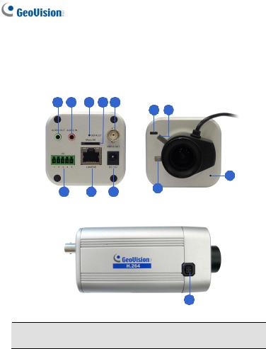
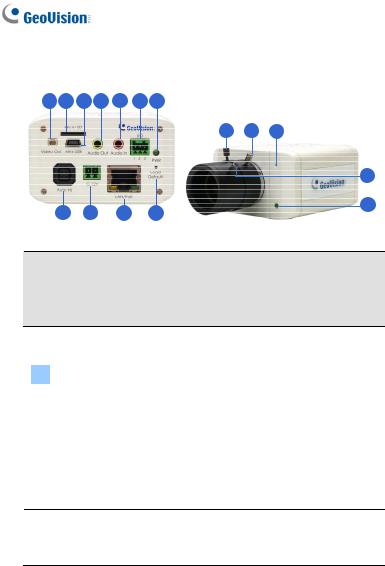
GV-BX120D / 130D Series / 140DW / 220D Series / 320D Series / 520D-0
1 2 3 4 5 6
11 |
12 13 |
14
15
16
7 8 9 10
Note:
1.The Light Sensor (No. 11) is only available in GV-BX140DW. Keep the Light sensor unobscured for accurate light detection.
2.The Iris Screw (No. 13) is only available for GV-BX520D-0.
3.The Zoom Screw (No. 15) is not available for GV-BX110D (fixed lens model) and GV-BX130D-1.
No. |
|
Name |
|
Description |
|
|
|
|
Connects to a portable monitor for setting |
1 |
|
Video Out |
|
the focus and angle of Box Camera during |
|
|
|
|
initial installation. |
2 |
|
Memory Card Slot |
|
Inserts a micro SD / SDHC / SDXC card to |
|
|
store recording data. |
||
|
|
|
|
|
3 |
|
Audio Out |
Connects a speaker for audio output. |
|
4 |
|
Audio In |
Connects a microphone for audio input. |
|
|
|
|
|
Connects I/O devices. For details, see I/O |
5 |
|
I/O Terminal Block |
|
Terminal Block, Box Camera Chapter, |
|
|
GV-IPCam H.264 User’s Manual on the |
||
|
|
|
|
|
|
|
|
|
Software DVD. |
6 |
|
Power LED |
|
Indicates the power is supplied. For detail, |
|
|
see the table below. |
||
|
|
|
|
|
4
|
|
|
|
|
1 |
Box Camera |
|
|
|
|
|
|
|
||
No. |
|
Name |
|
Description |
|
||
|
|
|
|
Plug the iris control cable to the connector. |
|||
7 |
|
Auto Iris |
|
Note that Auto Iris Connector is not functional |
|||
|
Connector |
|
in GV-BX130D-1, GV-BX140DW and |
||||
|
|
|
|||||
|
|
|
|
GV-BX520D-0. |
|
||
8 |
|
DC 12V Port |
|
Connects to power. |
|
||
9 |
|
LAN / PoE |
|
Connects to a 10/100 Ethernet or PoE. |
|
||
10 |
|
Default |
|
Resets all configurations to factory default. See |
|||
|
|
12. Restoring to Default Settings later in the |
|||||
|
|
|
|
Quick Start Guide. |
|
||
11 |
|
Light Sensor |
|
Detects light to switch between day and night |
|||
|
|
mode. |
|
||||
|
|
|
|
||||
12 |
|
Focus Screw |
Adjusts the focus of the camera. |
||||
|
|
|
|
|
|
||
13 |
|
Iris Screw |
|
Adjusts the iris of the camera |
|||
|
|
|
|
|
|||
14 |
|
Microphone |
Records the sounds. |
|
|||
15 |
|
Zoom Screw |
Adjusts the zoom of the camera |
|
|||
16 |
|
Status LED |
|
Turns on when the unit is ready for use. For |
|||
|
|
detail, see the table below. |
|||||
|
|
|
|
||||
|
|
|
|
||||
LED |
|
|
Description |
|
|||
Power LED turns green |
The system powers on and succeeds to boot up. |
|
|||||
Status LED turns green |
The system is ready for use. |
|
|||||
5
GV-BX1200 Series / 1300 Series / 2400 Series / 3400 Series / 5300-6V
1 2 3 4 5 6 7
8 9 10 11
Note:
1.The Zoom Screw (No. 13) is not available in GV-BX1200-0F ~ 2F, GV-BX1300-0F ~ 2F, GV-BX2400-0F ~ 2F and GV-BX3400-0F ~2F.
2.The Iris Screw (No. 12) is only available for GV-BX5300-6V.
No. |
|
Name |
|
Description |
|
|
|
|
Connects to a portable monitor for setting the |
1 |
|
Video Out |
|
focus and angle of Box Camera during initial |
|
|
|
|
installation. |
2 |
|
Memory Card |
|
Inserts a micro SD / SDHC / SDXC card to |
|
Slot |
|
store recording data. |
|
|
|
|
||
3 |
|
Mini USB Slot |
|
Connects to a GV-WiFi Adapter. |
4 |
|
Audio Out |
Connects a speaker for audio output. |
|
5 |
|
Audio In |
|
Connects a microphone for audio input. |
6I/O Terminal Block
Connects I/O devices. For details, see I/O Terminal Block, Box Camera Chapter, GV-IPCam H.264 User’s Manual on the Software DVD.
6

1 Box Camera
No. |
|
Name |
|
Description |
7 |
|
Power LED |
|
Indicates the power is supplied. For detail, see |
|
|
the table below. |
||
|
|
|
|
8Auto Iris Connector
Plug the iris control cable to the connector. Note that Auto Iris Connector is not functional in GV-BX1200-0F ~ 2F, GV-BX1300-0F ~ 2F, GV-BX2400-0F ~ 2F and GV-BX3400-0F ~ 2F.
9 |
DC 12V Port |
|
Connects to power. |
10 |
LAN / PoE |
|
Connects to a 10/100 Ethernet or PoE. |
|
|
|
Resets all configurations of the GV-IPCAM |
11 |
Default |
|
H.264 to the default factory settings. See 12. |
|
Restoring to Default Settings later in the Quick |
||
|
|
|
|
|
|
|
Start Guide. |
12 |
Iris Screw |
Adjusts the iris of the camera. |
|
13 |
Zoom Screw |
Adjusts the zoom of the camera. |
|
14 |
Microphone |
Records the sounds. |
|
15 |
Focus Screw |
Adjusts the focus of the camera. |
|
16 |
Status LED |
|
Turns on when the unit is ready for use. For |
|
|
|
detail, see the table below. |
|
|
|
|
LED |
|
|
Description |
Power LED turns green |
The system powers on and succeeds to boot up. |
||
Status LED turns green |
The system is ready for use. |
||
7
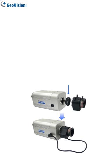
1.3 Accessory Installation
1.3.1 C-Mount Lenses
When you use a C-mount lens, it requires a certain distance from the camera’s imaging chip to focus the lens. Mount the supplied C-mount lens adapter / lens ring to the camera, and then attach the lens onto the camera body.
GV-BX110D
Install the supplied C-mount lens adapter to extend focal length for GV-BX110D as illustrated below.
C-mount lens adapter
8

1 Box Camera
Box Camera (except GV-BX110D)
Three type of lens rings are provided for Box Camera (except GV-BX110D):
•0.188 mm (transparent color) x 2
•0.125 mm (black color with a glossy surface) x 2
•0.254 mm (black color with a matt surface) x 2
For GV-BX140DW, a 0.125 mm lens ring is provided.
Note: These lens rings are specially designed for varifocal models of Box Camera (except GV-BX110D). Besides the supplied lens rings, each varifocal model has already been installed with the necessary lens ring.
9
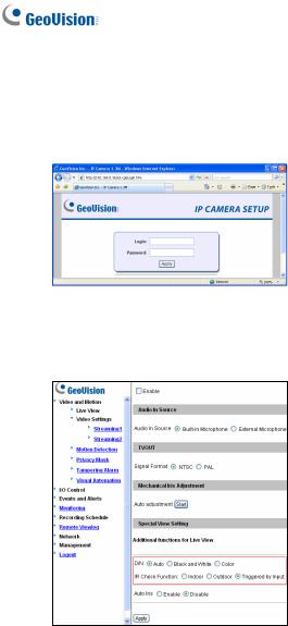
1.3.2 Infrared Illuminators (GV-IR LED / GV-IR LED T2)
1.Connect the infrared illuminator to the terminal block on the camera. See I/O Terminal Block, Box Camera Chapter, GV-IPCam H.264 User’s Manual on the Software DVD, or GV-IR LED User’s Manual.
2.Access the Web interface of the camera.
3.Select Video and Motion, select Video Settings, select Streaming 1 and set the IR Check Function option to be Trigger by Input (for GV-IR LED) or Trigger IR by D/N (for GV-IR LED T2).
GV-IR LED
10
 Loading...