


 Loading...
GV-AS/EV Controller
User’s Manual
Before attempting to connect or operate this product, please
read these instructions carefully and save this manual for future use.
ASEV-G

© 2015 GeoVision, Inc. All rights reserved.
Under the copyright laws, this manual may not be copied, in whole or in part, without the written consent of GeoVision.
Every effort has been made to ensure that the information in this manual is accurate. GeoVision, Inc. makes no expressed or implied warranty of any kind and assumes no responsibility for errors or omissions. No liability is assumed for incidental or consequential damages arising from the use of the information or products contained herein. Features and specifications are subject to change without notice.
Note: No memory card slot or local storage function for Argentina.
GeoVision, Inc.
9F, No. 246, Sec. 1, Neihu Rd., Neihu District, Taipei, Taiwan Tel: +886-2-8797-8377
Fax: +886-2-8797-8335 http://www.geovision.com.tw
Trademarks used in this manual: GeoVision, the GeoVision logo and GV series products are trademarks of GeoVision, Inc. Windows and Windows XP are registered trademarks of Microsoft Corporation.
October 2015
Contents
Welcome.................................................................................................................. |
|
|
vii |
|
Important Notes for Maintaining Power Supply.................................................. |
viii |
|||
Elevator Control........................................................................................................ |
|
x |
||
Optional Devices |
..................................................................................................... |
xi |
||
Installation Considerations.................................................................................... |
xiv |
|||
Firmware and Software Compatibility ................................................................... |
xv |
|||
Definition................................................................................................................. |
|
|
xvi |
|
1. GV-AS100 / 1010 Controller ................................................................................. |
1 |
|||
1.1 |
Introduction |
.............................................................................................................. |
2 |
|
|
1.1.1 |
Main Features ............................................................................................... |
4 |
|
|
1.1.2 |
Packing List................................................................................................... |
5 |
|
|
1.1.3 GV-AS100 / 1010 Board Layout .................................................................... |
6 |
||
1.2 |
Installation................................................................................................................ |
|
7 |
|
|
1.2.1 Connecting Card Readers............................................................................. |
8 |
||
|
1.2.1.A Wiegand Readers (GV-AS100 Only) ..................................................... |
8 |
||
|
1.2.1.B RS485 Readers..................................................................................... |
9 |
||
|
1.2.1.C Network Readers (GV-AS1010 Only) ................................................... |
10 |
||
|
1.2.2 |
Connecting Input Devices ............................................................................ |
11 |
|
|
1.2.3 |
Connecting Output Devices.......................................................................... |
12 |
|
|
1.2.4 Connecting the PC ....................................................................................... |
14 |
||
|
1.2.4.A Connecting GV-AS100 to PC................................................................ |
15 |
||
|
1.2.4.B Connecting GV-AS1010 to PC.............................................................. |
16 |
||
|
1.2.4.C |
Switches (GV-AS100 Only) .................................................................. |
17 |
|
|
1.2.5 Connecting the Power.................................................................................. |
17 |
||
|
1.2.6 |
Fitting the Battery......................................................................................... |
18 |
|
|
1.2.7 Using the Function Keys (GV-AS1010 Only) ................................................ |
19 |
||
1.3 Programming Mode................................................................................................. |
20 |
|||
|
1.3.1 Quick Reference of Programming Table..................................................... |
22 |
||
|
1.3.2 |
Adding and Deleting a Card ......................................................................... |
24 |
|
|
1.3.2.A Adding a Card....................................................................................... |
24 |
||
|
1.3.2.B |
Deleting a Card..................................................................................... |
25 |
|
|
1.3.3 |
Resetting the APB Function ......................................................................... |
25 |
|
|
1.3.4 |
Accessing the Security Mode ....................................................................... |
26 |
|
|
1.3.4.A |
Enabling the Security Mode .................................................................. |
26 |
|
|
1.3.4.B |
Disabling the Security Mode ................................................................. |
26 |
|
|
1.3.5 |
Setting Parameters ...................................................................................... |
27 |
|
i

|
1.3.6 |
Displaying System Information..................................................................... |
29 |
|
1.3.7 |
Restoring Factory Defaults........................................................................... |
30 |
1.4 |
Web-Based Configurations ..................................................................................... |
31 |
|
1.5 |
GV-AS100 / 1010 Specifications ............................................................................. |
32 |
|
2. GV-AS110 / 1110 Controller ............................................................................... |
34 |
||
2.1 |
Introduction ............................................................................................................. |
35 |
|
|
2.1.1 |
Main Features .............................................................................................. |
37 |
|
2.1.2 |
Packing List.................................................................................................. |
38 |
2.2 |
Installation............................................................................................................... |
39 |
|
|
2.2.1 Connecting Card Readers............................................................................ |
41 |
|
|
2.2.1.A Wiegand Readers (GV-AS110 Only) .................................................... |
41 |
|
|
2.2.1.B Network Readers (GV-AS1110 Only) ................................................... |
41 |
|
|
2.2.2 |
Connecting Input Devices ............................................................................ |
42 |
|
2.2.3 |
Connecting Output Devices.......................................................................... |
43 |
|
2.2.4 |
Connecting to the PC ................................................................................... |
45 |
|
2.2.4.A Connecting GV-AS110 to PC................................................................ |
45 |
|
|
2.2.4.B Connecting GV-AS1110 to PC.............................................................. |
46 |
|
|
2.2.5 Connecting the Power.................................................................................. |
47 |
|
2.3 |
Programming Mode................................................................................................. |
48 |
|
|
2.3.1 |
Adding and Deleting Cards .......................................................................... |
48 |
|
2.3.1.A Adding a Card....................................................................................... |
49 |
|
|
2.3.1.B Deleting a Card..................................................................................... |
50 |
|
|
2.3.2 Programming the GV-AS110 / 1110............................................................. |
51 |
|
2.4 |
LED Status and Beeper .......................................................................................... |
54 |
|
2.5 |
Web-Based Configurations ..................................................................................... |
56 |
|
2.6 |
GV-AS110 / 1110 Specifications ............................................................................ |
57 |
|
3. GV-AS120 Controller .......................................................................................... |
59 |
||
3.1 |
Introduction ............................................................................................................. |
60 |
|
|
3.1.1 |
Main Features .............................................................................................. |
62 |
|
3.1.2 |
Packing List.................................................................................................. |
62 |
3.2 |
Installation............................................................................................................... |
63 |
|
|
3.2.1 Connecting a Wiegand Reader .................................................................... |
64 |
|
|
3.2.2 |
Connecting Input Devices ............................................................................ |
64 |
|
3.2.3 |
Connecting Output Devices.......................................................................... |
65 |
|
3.2.4 |
Connecting to the PC ................................................................................... |
66 |
|
3.2.4.A RS-485 Connection .............................................................................. |
66 |
|
|
3.2.4.B Network Connection ............................................................................. |
68 |
|
|
3.2.5 Connecting the Power.................................................................................. |
68 |
|
ii
3.3 |
Programming Mode................................................................................................. |
69 |
|
3.3.1 Adding and Deleting Cards .......................................................................... |
69 |
|
3.3.1.A Adding a Card....................................................................................... |
70 |
|
3.3.1.B Deleting a Card..................................................................................... |
70 |
3.4 |
LED Status and Beeper .......................................................................................... |
71 |
3.5 |
Web-Based Configurations ..................................................................................... |
72 |
3.6 |
GV-AS120 Specifications........................................................................................ |
73 |
4. GV-AS210 / 2110 / 2120 Controller .................................................................... |
74 |
||
4.1 |
Introduction ............................................................................................................. |
75 |
|
|
4.1.1 |
Main Features .............................................................................................. |
75 |
|
4.1.2 |
Packing List.................................................................................................. |
76 |
|
4.1.3 |
Board Layout................................................................................................ |
77 |
4.2 |
Installation............................................................................................................... |
79 |
|
|
4.2.1 Connecting Card Readers............................................................................ |
79 |
|
|
4.2.1.A Wiegand Readers................................................................................. |
79 |
|
|
4.2.1.B RS-485 Readers................................................................................... |
80 |
|
|
4.2.2 |
Connecting Input Devices ............................................................................ |
81 |
|
4.2.3 |
Connecting Output Devices.......................................................................... |
82 |
|
4.2.4 |
Connecting Backup Battery.......................................................................... |
83 |
|
4.2.5 Connecting the Power.................................................................................. |
84 |
|
|
4.2.6 Connecting the PC ....................................................................................... |
86 |
|
|
4.2.7 |
Fitting the Battery (GV-AS2110 / 2120 Only)................................................ |
87 |
4.3 |
Other Settings......................................................................................................... |
88 |
|
|
4.3.1 Web Setting Switch ...................................................................................... |
88 |
|
|
4.3.2 |
Resetting the Controller................................................................................ |
88 |
|
4.3.3 |
Restoring Factory Defaults........................................................................... |
89 |
4.4 |
The Web Interface................................................................................................... |
90 |
|
4.5 |
GV-AS210 / AS2110 / AS2120 Specifications......................................................... |
91 |
|
5. GV-AS410 / 4110 / 810 / 8110 Controller |
........................................................... 92 |
||
5.1 |
Introduction ............................................................................................................. |
93 |
|
|
5.1.1 |
Main Features .............................................................................................. |
93 |
|
5.1.2 |
Packing List.................................................................................................. |
94 |
5.2 |
Installation............................................................................................................... |
96 |
|
|
5.2.1 Connecting Card Readers............................................................................ |
96 |
|
|
5.2.1.A Wiegand Readers................................................................................. |
96 |
|
|
5.2.1.B RS-485 Readers................................................................................... |
97 |
|
|
5.2.2 |
Connecting Input Devices ............................................................................ |
99 |
|
5.2.3 |
Connecting Output Devices........................................................................ |
100 |
iii

|
5.2.4 Connecting Backup Battery........................................................................ |
101 |
|
5.2.5 Connecting the Power................................................................................ |
101 |
|
5.2.6 Connecting the PC ..................................................................................... |
102 |
5.3 |
Other Settings....................................................................................................... |
103 |
|
5.3.1 Web Setting Switch .................................................................................... |
103 |
|
5.3.2 Resetting the GV-AS410 / 4110 / 810 / 8110.............................................. |
103 |
|
5.3.3 Restoring Factory Defaults......................................................................... |
104 |
5.4 |
GV-AS410 / 4110 / 810 / 8110 Kit (Optional)......................................................... |
105 |
|
5.4.1 Packing List................................................................................................ |
105 |
|
5.4.2 Overview.................................................................................................... |
106 |
|
5.4.3 Connecting the GV-AS410 / 4110 / 810 / 8110 Kit...................................... |
107 |
|
6.4.4 GV-AS410 / 4110 / 810 / 8110 Kit Specifications ....................................... |
109 |
5.5 |
The Web Interface................................................................................................. |
110 |
5.6 |
GV-AS410 / 4110 / 810 / 8110 Specifications........................................................ |
111 |
6. GV-EV48 Controller .......................................................................................... |
112 |
||
6.1 |
Introduction ........................................................................................................... |
113 |
|
|
6.1.1 |
Main Features ............................................................................................ |
113 |
|
6.1.2 |
Packing List................................................................................................ |
113 |
6.2 |
Installation............................................................................................................. |
115 |
|
|
6.2.1 Connecting RS-485 Card Readers............................................................. |
115 |
|
|
6.2.2 |
Connecting Output Relay ........................................................................... |
116 |
|
6.2.3 |
Connecting Backup Battery........................................................................ |
117 |
|
6.2.4 Connecting the Power................................................................................ |
117 |
|
|
6.2.5 Connecting the PC ..................................................................................... |
118 |
|
6.3 |
Other Settings....................................................................................................... |
119 |
|
|
6.3.1 Web Setting Switch .................................................................................... |
119 |
|
|
6.3.2 Resetting the GV-EV48.............................................................................. |
119 |
|
|
6.3.3 |
Restoring Factory Defaults......................................................................... |
120 |
6.4 |
The Web Interface................................................................................................. |
121 |
|
6.5 |
GV-EV48 Specifications........................................................................................ |
122 |
|
7. Installing on a Network .................................................................................... |
123 |
||
7.1 |
Fixed IP Connection.............................................................................................. |
125 |
|
7.2 |
DHCP Connection................................................................................................. |
127 |
|
|
7.2.1 |
Connection over LAN ................................................................................. |
127 |
|
7.2.2 |
Connection over Internet ............................................................................ |
130 |
8. The Web Interface............................................................................................. |
133 |
8.1 Basic Settings ....................................................................................................... |
135 |
8.1.1 System Setup............................................................................................. |
135 |
iv
8.1.2 Upgrading Firmware................................................................................... |
137 |
||
8.1.3 Changing Login ID and Password .............................................................. |
138 |
||
8.2 Advanced Settings ................................................................................................ |
139 |
||
8.2.1 |
Function Configuration ............................................................................... |
141 |
|
8.2.2 |
Parameter Configuration ............................................................................ |
144 |
|
8.2.2.A GV-AS1010 / 1110 / 210 / 2110 / 2120 / 410 / 4110 / 810 / 8110........ |
144 |
||
8.2.2.B GV-EV48 ............................................................................................ |
148 |
||
8.2.3 |
Card Configuration ..................................................................................... |
150 |
|
8.2.4 |
Card Information ........................................................................................ |
151 |
|
8.2.5 |
Time Configuration..................................................................................... |
152 |
|
8.2.6 |
Input Configuration..................................................................................... |
154 |
|
8.2.7 |
Output Configuration .................................................................................. |
157 |
|
8.2.7.A |
Output Function Settings .................................................................... |
159 |
|
8.2.7.B |
Output Condition Settings................................................................... |
160 |
|
8.2.8 Wiegand Configuration............................................................................... |
162 |
||
8.2.9 |
Function Key Configuration ........................................................................ |
163 |
|
8.3 Extended Device................................................................................................... |
164 |
||
8.3.1 Extended Reader ....................................................................................... |
164 |
||
9. Optional Devices .............................................................................................. |
168 |
||
9.1 Optional GV-ASBox .............................................................................................. |
169 |
||
9.1.1 |
Main Features ............................................................................................ |
169 |
|
9.1.2 |
Packing List................................................................................................ |
169 |
|
9.1.3 GV-ASBox Board Layout............................................................................ |
170 |
||
9.1.4 |
Installation.................................................................................................. |
171 |
|
9.1.4.A Connecting GV-AS100 / 110 / 120...................................................... |
171 |
||
9.1.4.B Connecting a Wiegand Reader........................................................... |
172 |
||
9.1.4.C Connecting GV-Readers and GV-GF Fingerprint Readers ................. |
173 |
||
9.1.4.D |
Connecting Input Devices................................................................... |
174 |
|
9.1.4.E |
Connecting Output Devices ................................................................ |
175 |
|
9.1.4.F |
Connecting Backup Battery................................................................. |
177 |
|
9.1.4.G |
Other Settings .................................................................................... |
178 |
|
9.1.5 GV-ASBox Specifications........................................................................... |
179 |
||
9.2 Optional GV-ASNet............................................................................................... |
180 |
||
9.2.1 |
Main Features ............................................................................................ |
180 |
|
9.2.2 |
Packing List................................................................................................ |
180 |
|
9.2.3 GV-ASNet Overview .................................................................................. |
181 |
||
9.2.4 |
Installation.................................................................................................. |
182 |
|
9.2.4.A Connecting GV-AS100 / 110 / 120...................................................... |
182 |
||
9.2.4.B Connecting GV-Readers and GV-GF Fingerprint Readers ................. |
183 |
||
|
|
|
v |

9.2.4.C |
Connecting Backup Battery ................................................................ |
184 |
|
9.2.4.D |
Other Settings .................................................................................... |
185 |
|
9.2.5 |
GV-ASNet Specifications ........................................................................... |
186 |
|
9.3 Web Interface through Optional Devices ............................................................... |
187 |
||
9.3.1 |
Basic Setting .............................................................................................. |
187 |
|
9.3.2 |
Advanced Settings ..................................................................................... |
188 |
|
9.3.2.A |
Function Setting.................................................................................. |
189 |
|
9.3.2.B |
Parameter Setting............................................................................... |
192 |
|
9.3.2.C |
Status Monitor .................................................................................... |
196 |
|
9.3.2.D |
Card Information................................................................................. |
197 |
|
9.3.2.E |
Time Setting ....................................................................................... |
198 |
|
9.3.2.F |
In/Out Function ................................................................................... |
199 |
|
9.3.2.G Extended Reader ............................................................................... |
206 |
||
10. Troubleshooting ............................................................................................ |
208 |
||
Appendix ............................................................................................................... |
|
|
214 |
A. GV-MountA900 for GV-AS110 / 1110 (Optional)..................................................... |
215 |
||
vi
Welcome
This user manual includes the following types of GV-AS / GV-EV Controllers:
GV-AS Controllers
|
|
|
|
Doors Supported |
|
|
Page |
|||
|
|
|
|
One-Way Control |
|
|
Two-Way Control |
|
|
Number |
|
|
|
|
|
|
|
|
|
||
|
|
|
|
|
|
|
|
|
|
|
|
GV-AS100 / 1010 |
|
1 |
|
1 |
|
|
See p. 1 |
||
|
GV-AS110 / 1110 |
|
1 |
|
1 |
|
|
See p. 34 |
||
|
GV-AS120 |
|
1 |
|
1 |
|
|
See p. 59 |
||
|
GV-AS210 / 2110 / |
|
4 |
|
|
2 (Wiegand only) |
|
See p. 74 |
||
|
2120 |
|
|
|
4 (Wiegand + RS-485 / Network) |
|
||||
|
|
|
|
|
|
|
|
|||
|
GV-AS410 / 4110 |
|
4 |
|
4 |
|
|
See p. 92 |
||
|
GV-AS810 / 8110 |
|
8 |
|
|
4 (Wiegand only), |
|
See p. 92 |
||
|
|
|
|
8 (RS-485 / Network) |
|
|||||
|
|
|
|
|
|
|
|
|
||
|
GV-EV Controllers |
|
|
|
|
|
|
|
|
|
|
|
|
|
Floors Supported |
|
|
Readers Supported |
|
|
Page |
|
|
|
|
|
|
|
|
|
|
Number |
|
GV-EV48-24 Floors |
|
24 |
|
|
2 (RS-485 or Network) |
|
See p.112 |
||
|
GV-EV48-48 Floors |
|
48 |
|
|
|
||||
|
|
|
|
|
|
|
|
|||
|
|
|
|
|
|
|
|
|
|
|
vii

Important Notes for Maintaining Power Supply
To make sure GV-AS / EV Controllers can function properly during a power outage, be sure to replace the internal battery on the controllers when needed. It is also recommended to install a backup battery for compatible GV-AS Controllers.
Refer to the following sections for instructions on how to install a backup battery:
GV-AS100 / 110 / 120 through GV-ASBox: See 9.1.4.F Connecting Backup Battery.
GV-AS100 / 110 / 120 through GV-ASNet: See 9.2.4.F Connecting Backup Battery.
GV-AS210 / 2110 / 2120: See 4.2.4 Connecting Backup Battery.
GV-AS410 / 4110 / 810 / 8110: See 5.2.4 Connecting Backup Battery.
GV-EV48: See 6.2.3 Connecting Backup Battery.
The table below lists the types of internal batteries used by different GV-AS / EV Controllers.
|
Type of Battery |
|
|
GV-AS / EV Controllers |
|
|
|
Replaceable Button Cell |
|
|
GV-AS100 / 2110 |
/ 2120 |
/ 4110 / 8110 |
|
Built-in Battery |
|
|
GV-AS1010 / 110 |
/ 1110 |
/ 120 / 210 / 410 / 810 |
|
|
|
GV-EV48 |
|
|
|
|
|
|
|
|
|
|
|
|
|
|
|
|
|
Replaceable Button Cell (GV-AS100 / 2110 / 2120 / 4110 / 8110)
For GV-AS100 / 2110 / 2120 / 4110 / 8110, you can replace the battery on your own when you see low battery messages and icons in GV-ASManager.
viii
Note: Make sure the plastic insulation film under the battery is removed when using GVAS100 / 2110 / 2120 / 4110 / 8110 for the first time. The low battery messages and icons will appear if the plastic film is not removed.
Built-in Battery (GV-AS1010 / 110 / 1110 / 120 / 210 / 410 / 810 & GV-EV48)
When the controller runs out of battery, the local time on the controller will be reverted back to 1999/12/31. The controller time can be found on the Web interface of the controller on the Time Configuration page and in the Access Monitor / Alarm Monitor / Event Monitor of GVASManager.
When you see the controller year shown as 1999 or 2000, disconnect the controller from power and reconnect it to power. If the year is still shown as 1999 or 2000, the controller battery needs to be replaced. When this occurs, connect the controller to a backup battery and maintain connection with GV-ASManager at all times. When connected to GVASManager, the controller’s time will be synchronized with GV-ASManager’s time.
ix

Elevator Control
GV-AS / GV-EV Controllers provide two types of elevator control.
For GV-AS100 / 1010 / 110 / 1110 / 120 / 210 / 2110 / 2120 / 410 / 4110 / 810 / 8110, the GV-AS Controller can control access to the elevator call buttons. Users who present the correct identification card to the elevator reader will be able to use the elevator and can go any floors. The output relays are connected to the call button of the elevator.
For GV-EV48, a controller especially designed for elevator control, access can be granted to specific floors. You can configure each identification card to specify the floors it can access. In this type of elevator control, each output relay is connected to the button of corresponding floor in the elevator control panel.
x
Optional Devices
Optional devices can expand the capabilities and versatilities of your GV-AS / GV-EV Controllers. Consult your sales representative for more information.
|
GV-Reader |
|
GV-Reader 1251 is a card reader that uses a 125 kHz frequency. It has |
|
|
both Wiegand and RS-485 outputs that can be connected to any standard |
|
|
1251 |
|
|
|
|
access control panel. |
|
|
|
|
|
|
|
|
|
|
GV-Reader |
|
GV-Reader 1352 V2 is a card reader that uses a 13.56 MHz frequency. It |
|
|
has both Wiegand and RS-485 outputs that can be connected to any |
|
|
1352 V2 |
|
|
|
|
standard access control panel. |
|
|
|
|
|
|
|
|
|
|
GV-RK1352 |
|
GV-RK1352 is a card reader with keypad that uses a 13.56 MHz |
|
|
frequency. The reader has both Wiegand and RS-485 outputs that can be |
|
|
|
|
connected to any standard access control panel. |
|
|
|
|
|
GV-R1352 |
|
GV-R1352 is a card reader that uses a 13.56 MHz frequency. The reader |
|
|
has both Wiegand and RS-485 outputs that can be connected to any |
|
|
|
|
standard access control panel. |
|
|
|
|
|
|
|
The reader supports three operation modes: Fingerprint Only, Fingerprint + |
|
GV-GF |
|
Card and Card Only. In Fingerprint Only mode, the fingerprints are enrolled |
|
|
through GV-ASManager. In Fingerprint + Card mode, the fingerprint |
|
|
Fingerprint |
|
|
|
|
templates are stored on the user card. In Card Only mode, the users only |
|
|
Reader |
|
|
|
|
|
need to swipe the card to be granted access. Readers with optical and |
|
|
|
capacitance sensors are available. |
|
|
|
|
|
GV-CR420 |
|
GV-CR420 is a card reader with a built-in 4MP wide angle IP camera. The |
|
|
card reader recognizes identification cards and transmits live view through |
|
|
|
|
network connection. |
|
|
|
|
|
|
|
The GV-DFR1352 is a card reader designed to be installed on the door |
|
GV-DFR1352 |
|
frame for recognizing identification cards. Featured with the Wiegand and |
|
|
RS-485 outputs, the unit can be connected to any standard access control |
|
|
|
|
|
|
|
|
panel. |
|
|
|
|
|
GV-ASBox |
|
Only works with GV-AS100 / 110 / 120. The device can add Network |
|
|
function, 1 Wiegand interface, 8 additional inputs and outputs to GV- |
|
|
|
|
AS100, GV-AS110 and GV-AS120. |
|
|
|
|
|
GV-ASNet |
|
Only works with GV-AS100 / 110 / 120. This device can add Network |
|
|
function to GV-AS100, GV-AS110 and GV-AS120. |
|
|
|
|
|
|
|
|
|
xi

|
GV-Hub |
|
Only works with GV-AS100 / 110 / 120. GV-Hub can convert the standard |
|
|
RS-232 signal of up to 4 controllers to RS-485, allowing the controllers to |
|
|
|
|
connect to computers. |
|
|
|
|
|
GV-COM |
|
Only works with GV-AS100 / 110 / 120. GV-COM can convert the |
|
|
standard RS-232 signal of one controller to RS-485, allowing the controller |
|
|
|
|
to connect to a computer. |
|
|
|
|
|
GV-Net / IO |
|
Only works with GV-AS100 / 110 / 120. GV-Net / IO Card can convert the |
|
|
standard RS-232 signal of one controller to RS-485, allowing the controller |
|
|
Card |
|
|
|
|
to connect to a computer. |
|
|
|
|
|
|
|
|
|
|
GV-AS410 / |
|
Only available for GV-AS410 / 4110 / 810 / 8110. Includes a GV-AS410 / |
|
|
4110 / 810 / 8110, a power adapter board, a power supply and a casing for |
|
|
4110 / 810 / |
|
|
|
|
backup battery. The power supply provides power to the controller and up |
|
|
8110 Kit |
|
|
|
|
to 8 output devices (12V, 0.9A per device). |
|
|
|
|
|
|
|
|
|
|
|
|
Only available for GV-AS410 / 4110 / 810 / 8110 and GV-EV48. With the |
|
|
|
cabinet, GV-AS / GV-EV Controllers can be mounted directly to a wall or |
|
|
|
recessed into the wall. Two types of cabinet dimensions are available (W x |
|
Cabinet |
|
H x D): |
|
|
|
• 383.5 x 443.5 x 112.2 mm / 15.1 x 17.5 x 4.4 in |
|
|
|
• 300 x 420 x 86 mm / 11.8 x 16.5 x 3.4 in |
|
|
|
|
|
|
|
Only available for GV-AS110 / 1110. GV-MountA900 is a mounting plate |
|
GV-MountA900 |
|
that allows you to attach GV-AS110 / 1110 to a US single gang power box. |
|
|
• Dimensions: 100 x 68 mm / 3.9 x 2.7 in |
|
|
|
|
|
|
|
|
• Weight: 55 g / 0.12 lb |
|
|
|
|
|
|
|
The push button switch can be integrated with access control system, |
|
Push Button |
|
allowing door exit by momentarily activating or deactivating the electric |
|
Switch |
|
locking device. Both American standard and European standard push |
|
|
|
buttons are available. |
|
|
|
|
|
GV-IB25 / 65 / |
|
The GV-IB25 / 65 / 85 Infrared Button detects infrared movement within 3 |
|
85 Infrared |
|
to 12 cm and allows you to open the door with a wave of hand. |
|
Button |
|
|
|
|
|
|
|
Electric Lock |
|
Three types of electric locks are available: electromagnetic lock, electric |
|
|
bolt and electric strike. |
|
|
|
|
|
|
|
|
|
|
GV-AS ID Card |
|
GV-AS ID Cards and GV-AS ID Tags are ideal for business and residential |
|
& GV-AS ID |
|
environment, where access control is important for security reasons. 125 |
|
Tag |
|
kHz and 13.56 MHz cards and tags are available. |
|
|
|
|
|
|
|
|
xii
|
Only works with GV-AS2120. The GV-POE Switch is designed to provide |
GV-POE |
power along with network connection for IP devices. The GV-POE Switch |
Switch |
is available in various models with different numbers and types of ports. |
|
GV-AS2120 requires PoE that provides at least 25.5 W (IEEE 802.3at). |
|
|
Power Adapter |
Contact your sales representative for the countries and areas supported. |
|
|
xiii

Installation Considerations
1. There are distance limitations for Wiegand and RS-485 communications. Please note:
•Wiegand interface:
Recommended Wiegand cable: Wiegand cable (a twisted pair of 24 AWG wires)
100 meters (328.1 feet) for GV-AS2110 / 2120 / 4110 / 8110
30 meters (98.43 feet) for other GV-AS Controllers
•RS-485 interface: 600 meters (1968.50 feet)
Recommended RS-485 cable: standard 485 cable (a twisted pair of 24 AWG wires)
2.GV-ASManager software is used to manage GV-AS / GV-EV Controllers. There is a limit for the number of controllers connected to GV-ASManager based on communication modes.
•Through network connection, up to 1000 GV-AS / GV-EV Controllers can connect to GV-ASManager.
•Through RS-485 connection, up to 16 GV-AS100 / 110 / 120 Controllers can connect to the same COM port on a computer running GV-ASManager.
3.When presenting cards to GeoVision readers and the built-in readers of GV-AS100 / 1010 / 110 / 1110 / 120, make sure only one card is presented at a time to avoid frequency interference.
Note:
1.For RS-485 connection between GV-AS Controllers and readers, user additional power for the readers when the distance ranges from 30.48 ~ 600 meters (100 ~ 1968.50 ft). There is no need to use additional power when the distance is within 30.48 meters (100 ft).
2.For GV-AS100 / 2110 / 2120 / 4110 / 8110, it is highly recommended to replace the button cell battery included on the circuit board annually.
xiv
Firmware and Software Compatibility
The GV-AS / GV-EV Controllers firmware versions compatible with GV-ASManager V4.0 - V4.3 are listed below.
|
|
|
|
|
|
|
GV-ASManager |
|
|
||||
|
|
|
|
|
|
|
|
|
|
|
|
|
|
|
Models |
|
V4.0 |
|
|
V4.1 |
V4.2 |
|
V4.2.1 |
|
V4.2.2 |
V4.2.3 |
V4.3 |
|
|
|
|
|
|
|
|
|
|
|
|
|
|
|
GV-AS100 |
|
|
|
|
V1.06 |
|
|
|
|
V1.08 |
|
|
|
|
|
|
|
|
|
|
|
|
|
|
|
|
|
GV-AS110 / 120 |
|
|
|
|
V1.06 |
|
|
|
|
V1.07 |
|
|
|
|
|
|
|
|
|
|
|
|
|
|
|
|
|
GV-AS1010 / 1110 |
|
|
|
|
|
N/A |
|
|
|
|
V1.0 |
V1.1 |
|
|
|
|
|
|
|
|
|
|
||||
|
GV-AS410 |
|
|
V1.1 |
V1.2 |
|
V1.22 |
V1.23 |
V1.3 |
||||
|
|
|
|
|
|
|
|
|
|||||
|
GV-AS210 / 810 |
|
V1.1 or earlier |
V1.2 |
|
V1.22 |
V1.23 |
V1.3 |
|||||
|
|
|
|
|
|
|
|
|
|
|
|
|
|
|
GV-AS2110 / 4110 / 8110 |
|
|
|
|
|
N/A |
|
|
|
|
V1.23 |
V1.3 |
|
|
|
|
|
|
|
|
|
|
|
|
|
|
|
GV-AS2120 |
|
|
|
|
|
|
N/A |
|
|
|
V1.35 |
|
|
|
|
|
|
|
|
|
|
|
|
|
||
|
GV-EV48 |
|
N/A |
|
|
V1.0 |
V1.1 |
|
V1.11 |
V1.12 |
V1.3 |
||
|
|
|
|
|
|
|
|
|
|
|
|
|
|
|
GV-ASBox / GV-ASNet |
|
|
|
|
V1.06 |
|
|
|
|
V1.07 |
|
|
|
(Optional devices) |
|
|
|
|
|
|
|
|
|
|||
|
|
|
|
|
|
|
|
|
|
|
|
|
|
|
|
|
|
|
|
|
|
|
|
|
|
|
|
xv

Definition
Tampering Alarm GV-AS100 / 1010 / 110 / 1110 / 120 have built-in sensors to detect whether the controller is being physically tampered with (i.e. opening of the controller or sustaining strong impact). For GV-AS210 / 2110 / 2120 / 410 / 4110 / 810 / 8110, the tampering alarm sensor needs to be installed separately and the triggering conditions depend on the type of sensor installed.
The GV-AS Controller also provides output relays for activating and deactivating electric lock, siren and emergency door release when tampering is detected by the sensors.
For configuring input sensors and outputs, see Chapter 9 The Web
Interface or Web Interface through Optional Devices in Chapter 10 for
GV-AS100 / 110 / 120.
For settings of alarm conditions see Step 2: Configuring the Doors in
Chapter 4 of GV-ASManager User’s Manual.
xvi
1. GV-AS100 / 1010 Controller
1.1 Introduction
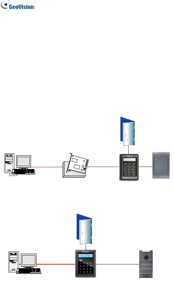
GV-AS100 / 1010 is a single door controller with a built-in a card reader and a LCD display.
You can connect one more card reader to GV-AS100, and up to two more card readers to GV-AS1010 for entry and exit applications. GV-AS100 / 1010 has the capability to store up to one thousand cards as a standalone model and up to 40,000 cards when connected to GV-ASManager. The programming is either done on the keypad or from the software GVASManager.
GV-AS100 / 1010 is suitable for controlling doors, parking gates and access to elevator call buttons.
Door
|
RS-232 |
RS-485 |
|
GV-ASManager |
GV-HUB / |
|
Wiegand / RS-485 |
|
GV-COM / |
GV-AS100 |
Reader |
|
GV-NET/IO Card |
IN |
OUT |
Figure 1-1
2
1 GV-AS100 / 1010 Controller
GV-AS100 can make network connection to GV-ASManager using the optional GV-ASBox or GV-ASNet. With GV-ASBox, two-door control is also possible as illustrated below.
Figure 1-2 Through GV-ASBox
Door
|
GV-ASNet |
|
|
|
|
RS-485 |
|
RS-485 |
TCP/IP |
GV-AS100 |
Wiegand / RS-485 |
Reader (x2) |
|
IN |
Reader |
|
|
|
OUT |
GVASManager
Figure 1-3 Through GV-ASNet
3

1.1.1 Main Features
GV-AS100
•1 door (one-way and two-way control), expandable to 2 doors with optional GV-ASBox
•1,000 / 40,000 cards (standalone / networked or RS-485 mode)
•Easy programming from keypad
•Built-in 3 digital inputs and 2 relay outputs
•1 Wiegand output (26 ~ 64 bits) and 1 RS-485 interface for extra reader programming
•Built-in 13.56 MHz Reader
•Built-in tampering alarm sensor
•IP54-compliant housing
•Anti-Passback (APB) support
GV-AS1010
•1 door (one-way and two-way control)
•1,000 / 40,000 cards (standalone / networked mode)
•Easy programming from keypad
•Function keys on keypad to register attendance data for GV-TAWeb
•Built-in 3 digital inputs and 2 relay outputs
•1 RS-485 interface for connecting to up to 2 readers
•1 network interface for connection with GV-ASManager and TCP/IP reader
•Built-in 13.56 MHz Reader
•Built-in tampering alarm sensor
•IP54-compliant housing
•Anti-Passback (APB) support
4

1 GV-AS100 / 1010 Controller
1.1.2 Packing List
GV-AS100
•GV-AS100
•Power Adaptor 12V DC / 1A
•Power Cord
•Screw x 3
•Screw Anchor x 2
•Master Card
•GV-AS ID F Card x 20
•Software CD
•Warranty Card
GV-AS1010
•GV-AS1010
•Power Adaptor 12V DC / 1.25A
•Screw x 3
•Screw Anchor x 2
•Enroll Card
•Delete Card
•GV-AS ID F Card x 20
•Torx Wrench
•Software CD
•Warranty Card
5
1.1.3 GV-AS100 / 1010 Board Layout
|
|
|
|
|
|
|
|
|
|
|
|
|
|
|
|
|
|
|
|
|
|
|
|
|
|
|
|
|
|
|
|
|
|
|
|
|
|
|
|
|
|
|
|
|
|
|
|
|
|
|
|
|
|
|
|
|
|
|
|
|
|
|
|
|
|
|
|
|
|
|
|
|
|
|
|
|
|
|
|
|
|
|
|
|
|
|
|
|
|
|
|
|
|
|
|
|
|
|
|
|
|
|
|
|
|
|
|
|
|
|
|
|
|
|
|
|
|
|
|
|
|
|
|
|
|
|
|
|
|
|
|
|
|
|
|
|
|
|
|
|
|
|
|
|
|
|
|
|
|
|
|
|
|
|
|
|
|
|
|
|
|
|
|
|
|
|
|
|
|
|
|
|
|
|
|
|
|
|
|
|
|
|
|
|
|
|
|
|
|
|
|
|
|
|
|
|
|
|
|
|
|
|
|
|
|
|
|
|
|
|
|
|
|
|
|
|
|
|
|
|
|
|
|
|
|
|
|
|
|
|
|
|
|
|
|
|
|
|
|
|
|
|
|
|
|
|
|
|
|
|
|
|
|
|
|
|
|
|
|
|
|
|
|
|
|
|
|
|
|
|
|
|
|
|
|
|
|
|
|
|
|
|
|
|
|
|
|
|
|
|
|
|
|
|
|
|
|
|
|
|
|
|
|
|
|
|
|
|
|
|
|
|
|
|
|
|
|
|
|
|
|
|
|
|
|
|
|
|
|
|
|
|
|
|
|
|
|
|
|
|
|
|
|
|
|
|
|
|
|
|
|
|
|
|
|
|
|
|
|
|
|
|
|
|
|
|
|
|
|
|
|
|
|
|
|
|
|
|
|
|
|
|
|
|
|
|
|
|
|
|
|
|
|
|
|
|
|
|
|
|
|
|
|
|
|
|
|
|
|
|
|
|
|
|
|
|
|
|
|
|
|
|
|
|
|
|
|
|
|
|
|
|
|
|
|
|
|
|
|
|
|
|
|
|
|
|
|
|
|
|
|
|
|
|
|
|
|
|
|
|
|
|
|
|
|
|
|
|
|
|
|
|
|
|
|
|
|
|
|
|
|
|
|
|
|
|
|
|
|
|
|
|
|
|
|
|
|
|
|
|
|
|
|
|
|
|
|
|
|
|
|
|
|
|
|
|
|
|
|
|
|
|
|
|
|
|
|
|
|
|
|
|
|
|
|
|
|
|
|
|
|
|
|
|
|
|
|
|
|
|
|
|
|
|
|
|
|
|
|
|
|
|
|
|
|
|
|
|
|
|
|
|
|
|
|
|
|
|
|
|
|
|
|
|
|
|
|
|
|
|
|
|
|
|
|
|
|
|
|
|
|
|
|
|
|
|
|
|
|
|
|
|
|
|
|
|
|
|
|
|
|
|
|
|
|
|
|
|
|
|
|
|
|
|
|
|
|
|
|
|
|
|
|
|
|
|
|
|
|
|
|
|
|
|
|
|
|
|
|
|
|
|
|
|
|
|
|
|
|
|
|
|
|
|
|
|
|
|
|
|
|
|
|
|
|
|
|
|
|
|
|
|
|
|
|
|
|
|
|
|
|
|
|
|
|
|
|
|
|
|
|
|
|
|
|
|
|
|
|
|
|
|
|
|
|
|
|
|
|
|
|
|
|
|
|
|
|
|
|
|
|
|
|
|
|
|
|
|
|
|
|
|
|
|
|
|
|
|
|
|
|
|
|
|
|
|
|
|
|
|
|
|
|
|
|
|
|
|
|
|
|
|
|
|
|
|
|
|
|
|
|
|
|
|
|
|
|
|
|
|
|
|
|
|
|
|
|
|
|
|
|
|
|
|
|
|
|
|
|
|
|
|
|
|
|
|
|
|
|
|
|
|
|
|
|
|
|
|
|
|
|
|
|
|
|
|
|
|
|
|
|
|
|
|
|
|
|
|
|
|
|
|
|
|
|
|
|
|
|
|
|
|
|
|
|
|
|
|
|
|
|
|
|
|
|
|
|
|
|
|
|
|
|
|
|
|
|
|
|
|
|
|
|
|
|
|
|
|
|
|
|
|
|
|
|
|
|
|
|
|
|
|
|
|
|
|
|
|
|
|
|
|
|
|
|
|
|
|
|
|
|
|
|
|
|
|
|
|
|
|
|
|
|
|
|
|
|
|
|
|
|
|
|
|
|
|
|
|
|
|
|
|
|
|
|
|
|
|
|
|
|
|
|
|
|
|
|
|
|
|
|
|
|
|
|
|
|
|
|
|
|
|
|
|
|
|
|
|
|
|
|
|
|
|
|
|
|
|
|
|
|
|
|
|
|
|
|
|
|
|
|
|
|
|
|
|
|
|
|
|
|
|
|
|
|
|
|
|
|
|
|
|
|
|
|
|
|
|
|
|
|
|
|
|
|
|
|
|
|
|
|
|
|
|
|
|
|
|
|
|
|
|
|
|
|
|
|
|
|
|
|
|
|
|
|
|
|
|
|
|
|
|
|
|
|
|
|
|
|
|
|
|
|
|
|
|
|
|
|
|
|
|
|
|
|
|
|
|
|
|
|
|
|
|
|
|
|
|
|
|
|
|
|
|
|
|
|
|
|
|
|
|
|
|
|
|
|
|
|
|
|
|
|
|
|
|
|
|
|
|
|
|
|
|
|
|
|
|
|
|
|
|
|
|
|
|
|
|
|
|
|
|
|
|
|
|
|
|
|
|
|
|
|
|
|
|
|
|
|
|
|
|
|
|
|
|
|
|
|
|
|
|
|
|
|
|
|
|
|
|
|
|
|
|
|
|
|
|
|
|
|
|
|
|
|
|
|
|
|
|
|
|
|
|
|
|
|
|
|
|
|
|
|
|
|
|
|
|
|
|
|
|
|
|
|
|
|
|
|
|
|
|
|
|
|
|
|
|
|
|
|
|
|
|
|
|
|
|
|
|
|
|
|
|
|
|
|
|
|
|
|
|
|
|
|
|
|
|
|
|
|
|
|
|
|
|
|
|
|
|
|
|
|
|
|
|
|
|
|
|
|
|
|
|
|
|
|
|
|
|
|
|
|
|
|
|
|
|
|
|
|
|
|
|
|
|
|
|
|
|
|
|
|
|
|
|
|
|
|
|
|
|
|
|
|
|
|
|
|
|
|
|
|
|
|
|
|
|
|
|
|
|
|
|
|
|
|
|
|
|
|
|
|
|
|
|
|
|
|
|
|
|
|
|
|
|
|
|
|
|
|
|
|
|
|
|
|
|
|
|
|
|
|
|
|
|
|
|
|
|
|
|
|
|
|
|
|
|
|
|
|
|
|
|
|
|
|
|
|
|
|
|
|
|
|
|
|
|
|
|
|
|
|
|
|
|
|
|
|
|
|
|
|
|
|
|
|
|
|
|
|
|
|
|
|
|
|
|
|
|
|
|
|
|
|
|
|
|
|
|
|
|
|
|
|
|
|
|
|
|
|
|
|
|
|
|
|
|
|
|
|
|
|
|
|
|
GV-AS100 |
|
|
|
|
|
|
|
|
GV-AS1010 |
|||||||||||||||||||||||||||
|
|
|
|
|
|
|
|
|
|
|
|
|
|
|
|||||||||||||||||||||||||||||
Figure 1-4
6

1 GV-AS100 / 1010 Controller
1.2 Installation
Open the GV-AS100 / 1010 to access the terminal block.
GV-AS100 |
|
|
|
|
|
|
|
|
|
|
|
|
|||||||
|
|
|
|
|
|
|
|
|
Pin |
|
|
Function |
|
|
Pin |
|
|
Function |
|
|
19 Door NO |
|
|
|
|
|
|
|
|
|
|
|
|
|
|
||||
|
|
|
|
|
|
|
|
|
|
|
|
|
|
|
|||||
|
18 Door NC |
|
|
|
|
|
|
1 |
|
|
12V Power |
11 |
|
|
Sensor IN1 |
||||
|
|
|
|
|
|
|
|
|
|
|
|||||||||
|
|
|
|
|
|
|
|
|
|
|
|||||||||
|
17 Door COM |
|
|
|
|
|
|
|
|
|
|
|
|
|
|
|
|
|
|
|
|
|
|
|
|
|
2 |
|
GND |
12 |
|
|
Button IN2 |
||||||
|
16 Alarm NO |
|
|
|
|
|
|
|
|
|
|||||||||
|
|
|
|
|
|
|
|
|
|
||||||||||
|
|
|
|
|
|
|
|
|
|
|
|
RS-485 A+ for ASBox / ASNet |
|
|
|
|
|
|
|
|
15 Alarm COM |
|
|
|
|
|
|
3 |
|
|
13 |
|
|
Fire IN3 |
|||||
|
|
|
|
|
|
|
|
|
|
|
|||||||||
|
|
|
|
|
|
|
|
|
|
|
|||||||||
|
14 IN COM |
|
|
|
|
|
|
|
|
or PC connection |
|
|
|||||||
|
|
|
|
|
|
|
|
|
|
|
|||||||||
|
|
|
|
|
|
|
|
|
|
|
|
|
|
|
|
|
|||
|
13 IN3 Fire |
|
|
|
|
|
|
|
|
|
|
|
|
|
|
|
|
|
|
4 |
|
|
RS-485 A-for ASBox / ASNet or |
14 |
|
IN COM |
|||||||||||||
|
|
|
|
|
|
|
|
|
|
||||||||||
|
|
|
|
|
|
|
|
|
|
||||||||||
|
12 IN2 Button |
|
|
|
|
|
|
|
|
|
|||||||||
|
|
|
|
|
|
|
|
|
PC connection |
|
|||||||||
|
|
|
|
|
|
|
|
|
|
||||||||||
|
11 IN1 Sensor |
|
|
|
|
|
|
|
|
|
|
|
|
|
|
|
|
||
|
|
|
|
|
|
|
|
|
|
|
|
|
|
|
|
|
|
|
|
|
|
|
|
RS-485 B+ for GV-Reader |
|
|
|
|
|
|
|||||||||
|
10 GND |
|
|
|
|
|
|
5 |
|
|
15 |
|
Alarm COM |
||||||
|
|
|
|
|
|
|
|
|
|
||||||||||
|
9 PWR Out 12V |
|
|
|
|
|
|
|
|
connection |
|
||||||||
|
|
|
|
|
|
|
|
|
|
|
|
|
|
|
|
|
|||
|
|
|
|
|
|
|
|
|
|
|
|
|
|
|
|
|
|||
|
8 Data1 |
|
|
|
|
|
|
|
|
|
|
|
|
|
|
|
|
|
|
|
|
|
|
|
|
|
6 |
|
|
RS-485 B- for GV-Reader |
16 |
|
Alarm NO |
||||||
|
|
|
|
|
|
|
|
|
|
||||||||||
|
7 Data0 |
|
|
|
|
|
|
|
|
|
|||||||||
|
|
|
|
|
|
|
|
|
connection |
|
|||||||||
|
|
|
|
|
|
|
|
|
|
||||||||||
|
6 RS485 B- |
|
|
|
|
|
|
|
|
|
|
|
|
|
|
|
|
|
|
7 |
|
|
Wiegand Data 0 |
17 |
|
Door COM |
|||||||||||||
|
5 RS485 B+ |
|
|
|
|
|
|
|
|
|
|||||||||
|
|
|
|
|
|
|
|
|
|
||||||||||
|
|
|
|
|
|
|
|
|
|
||||||||||
|
4 RS485 A- |
|
|
|
|
|
|
8 |
|
Wiegand Data 1 |
18 |
|
Door NC |
||||||
|
|
|
|
|
|
|
|
|
|||||||||||
|
|
|
|
|
|
|
|
|
|||||||||||
|
3 RS485 A+ |
|
|
|
|
|
|
|
|
||||||||||
|
|
|
|
|
|
|
|
|
|
|
|
|
|
|
|
|
|
|
|
9 |
|
12V Power Supply |
19 |
|
Door NO |
||||||||||||||
|
2 GND |
|
|
|
|
|
|
|
|
||||||||||
|
|
|
|
|
|
|
|
|
|||||||||||
|
|
|
|
|
|
|
|
|
|||||||||||
|
1 PWR In 12V |
|
|
|
|
|
|
10 |
|
GND |
|
|
|
|
|
|
|||
|
|
|
|
|
|
|
|
|
|
|
|
|
|
||||||
|
|
|
|
|
|
|
|
|
|
|
|
|
|
|
|
|
|
|
|
Figure 1-5
GV-AS1010
|
|
|
|
|
|
|
|
|
Pin |
|
|
Function |
|
|
Pin |
|
|
Function |
|
|
|
|
|
|
|
|
|
|
|
|
|
|
|
|
|
||||
|
|
|
|
|
|
|
|
|
|
|
|
|
|
|
|
||||
|
|
|
|
|
|
|
|
1 |
|
Door NC |
8 |
|
Input Fire |
||||||
|
|
|
|
|
|
|
|
|
|
||||||||||
|
|
|
|
|
|
|
|
|
|
||||||||||
|
|
|
|
|
|
|
|
|
|
|
|
|
|
|
|
|
|
|
|
|
|
|
|
|
|
|
|
2 |
|
Door NO |
9 |
|
|
Input Button |
|||||
|
|
|
|
|
|
|
|
|
|
|
|||||||||
|
|
|
|
|
|
|
|
|
|
|
|||||||||
|
|
|
|
|
|
|
|
|
|
|
|||||||||
|
|
|
|
|
|
|
|
3 |
|
|
Door COM |
10 |
|
|
Input Sensor |
||||
|
|
|
|
|
|
|
|
|
|
|
|
||||||||
|
|
|
|
|
|
|
|
|
|
|
|
||||||||
|
|
|
|
|
|
|
|
|
|
|
|
|
|
|
|
|
|
|
|
|
|
|
|
|
|
|
|
4 |
|
Alarm NC |
11 |
|
|
RS485 - |
|||||
|
|
|
|
|
|
|
|
|
|
|
|||||||||
|
|
|
|
|
|
|
|
|
|
|
|||||||||
|
|
|
|
|
|
|
|
|
|
|
|||||||||
|
|
|
|
|
|
|
|
5 |
|
|
Alarm NO |
12 |
|
|
RS485 + |
||||
|
|
|
|
|
|
|
|
|
|
|
|
||||||||
|
|
|
|
|
|
|
|
|
|
|
|
||||||||
|
|
|
|
|
|
|
|
|
|
|
|
||||||||
|
|
|
|
|
|
|
|
|
|
|
|
|
|
|
|
|
|
|
|
|
|
|
|
|
|
|
|
6 |
|
Alarm Com |
13 |
|
GND |
||||||
|
|
|
|
|
|
|
|
|
|
||||||||||
|
|
|
|
|
|
|
|
|
|
||||||||||
|
|
|
|
|
|
|
|
|
|
||||||||||
|
|
|
|
|
|
|
|
7 |
|
|
IN COM |
14 |
|
|
PWR In 12V |
||||
|
|
|
|
|
|
|
|
|
|
|
|
||||||||
|
|
|
|
|
|
|
|
|
|
|
|
||||||||
|
|
|
|
|
|
|
|
|
|
|
|
||||||||
|
|
|
|
|
|
|
|
|
|
|
|
|
|
|
|
|
|
|
|
|
|
|
|
|
|
|
|
|
|
|
|
|
|
|
|
|
|
|
|
|
|
|
|
|
|
|
|
|
|
|
|
|
|
|
|
|
|
|
|
|
|
|
|
|
|
|
|
|
|
|
|
|
|
|
|
|
|
|
|
|
|
|
|
|
|
|
|
|
|
|
|
|
|
|
|
|
|
|
|
|
|
|
|
|
|
|
|
|
|
|
|
|
|
|
|
|
|
|
|
|
|
|
|
|
|
|
|
|
|
|
|
|
|
|
|
|
|
|
|
|
|
|
|
|
|
|
|
|
|
|
|
|
|
|
|
|
|
|
|
Figure 1-6
7

1.2.1 Connecting Card Readers
1.2.1.A Wiegand Readers (GV-AS100 Only)
GV-AS100 provides one Wiegand input for connection of the Wiegand reader ranging from 26 to 64 bits. Through the GV-AS100 keypad, you can set the Wiegand reader as the entry or exit reader. To define the reader, see the AS100 Function option in 1.3.5 Setting Parameters.
Note: Wiegand connection is not supported for GV-AS1010.
The table below shows the pin assignments of the Wiegand input on GV-AS100. Please consult the documentation of your Wiegand reader for wiring.
Pin |
Function |
7 |
Wiegand Data 0 |
|
|
8 |
Wiegand Data 1 |
|
|
9 |
12V Power Supply |
|
|
10 |
GND |
|
|
8
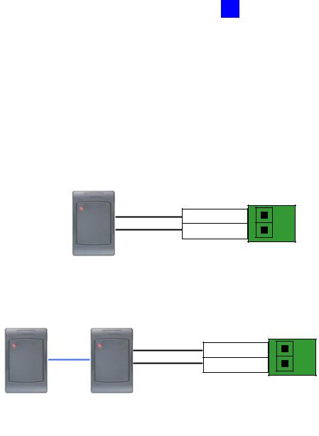
1 GV-AS100 / 1010 Controller
1.2.1.B RS485 Readers
For long-distance connection and non-Wiegand card readers, you can establish RS-485 connection with any GV-Readers and GV-GF1911 / 1912. GV-AS100 can connect with 1 reader through RS-485 connection. GV-AS1010 can connect with up to 2 readers through a single RS-485 cable.
When connecting a second reader to GV-AS1010, you will need to set up a separate power source to power the second reader.
Figure 1-7
9
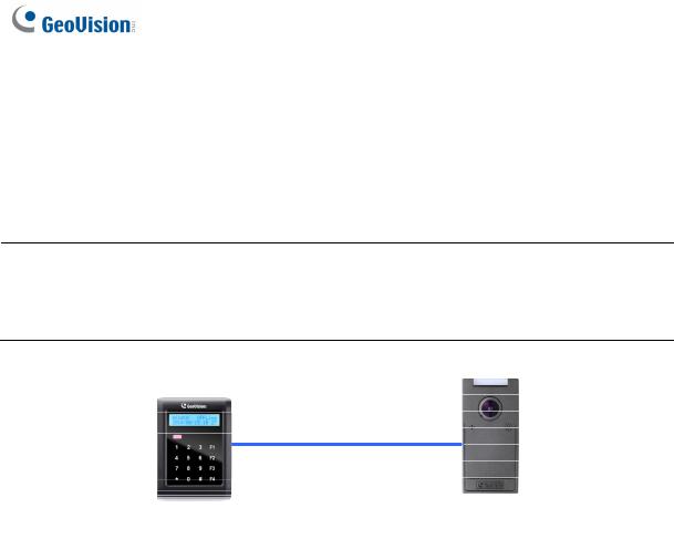
1.2.1.C Network Readers (GV-AS1010 Only)
GV-AS1010 supports network connection with GV-CR420 and GV-GF1921 / 1922. Through the GV-AS1010 keypad, you can set the network reader as the entry or exit reader. To define the reader, see the Door/Gate Function option in 2.3.2 Programming the GV-AS110 / 1110.
Note:
1.Network connection with readers is not supported for GV-AS110.
2.GV-AS1010 does not support network connection with GV-GF1911 / 1912.
Figure 1-8
10

1 GV-AS100 / 1010 Controller
1.2.2 Connecting Input Devices
GV-AS100 / 1010 supports 3 types of inputs:
1.Sensor inputs, e.g. door status sensor
2.Button inputs, e.g. door opener
3.Fire Sensor inputs, e.g. fire detector
All inputs are dry contact and can be configured as normally open (NO) or normally closed (NC) through the GV-AS100 / 1010 keypad. The default value is NO. To change the input status, see the Set Contact Type option in 1.3.5 Setting Parameters.
The table below shows the pin assignments of input connectors on GV-AS100 and GVAS1010.
GV-AS100
Pin |
Function |
11 |
Sensor IN1 |
|
|
12 |
Button IN2 |
|
|
13 |
Fire Sensor IN3 |
|
|
14 |
IN COM |
|
|
GV-AS1010 |
|
|
|
Pin |
Function |
7 |
IN COM |
|
|
8 |
Input Fire |
|
|
9 |
Input Button |
|
|
10 |
Input Sensor |
|
|
11

1.2.3 Connecting Output Devices
GV-AS100 supports 2 types of outputs:
1.Alarm outputs, e.g. siren or bell
2.Door outputs, e.g. electronic lock
The table below shows the pin assignments of output connectors on GV-AS100 / 1010.
GV-AS100
Pin |
Function |
|
|
15 |
Alarm COM |
|
|
|
|
|
|
16 |
Alarm NO |
|
|
|
|
|
|
17 |
Door COM |
|
|
|
|
|
|
18 |
Door NC |
|
|
|
|
|
|
19 |
Door NO |
|
|
|
|
|
|
GV-AS1010 |
|
||
|
|
|
|
Pin |
|
Function |
|
1 |
|
Door NC |
|
|
|
|
|
2 |
|
Door NO |
|
|
|
|
|
3 |
|
Door COM |
|
|
|
|
|
4 |
|
Alarm NC |
|
|
|
|
|
5 |
|
Alarm NO |
|
|
|
|
|
6 |
|
Alarm Com |
|
|
|
|
|
Check if your output device meets the following absolute maximum ratings before connecting it to the Door outputs.
Breakdown Voltage |
240V AC, 30V DC |
|
|
Continuous Load Current |
5A (NO), 3A (NC) |
|
|
Note: Absolute Maximum Ratings are those values beyond which damage to GVAS100 circuit board may occur. Continuous operation of GV-AS100 at the absolute rating level may affect GV-AS100 reliability.
12
Loading...