


 Loading...
Geovision GV-EBD4700, GV-EBD4711, GV-EBD8711, GV-TBL4710, GV-TBL8710 Quick Start Guide
...
Quick Start Guide
GV-IP Camera
 GV-EBD Series
 GV-ABL / TBL Series
 GV-ADR / TDR Series
 GV-AVD / TVD Series
Before attempting to connect or operate this product, |
UBN-QG-L |
please read these instructions carefully and save this manual for future use. |

© 2019 GeoVision, Inc. All rights reserved.
Under the copyright laws, this manual may not be copied, in whole or in part, without the written consent of GeoVision.
Every effort has been made to ensure that the information in this manual is accurate. GeoVision, Inc. makes no expressed or implied warranty of any kind and assumes no responsibility for errors or omissions. No liability is assumed for incidental or consequential damages arising from the use of the information or products contained herein. Features and specifications are subject to change without notice.
Note: No memory card slot or local storage function for Argentina.
GeoVision, Inc.
9F, No. 246, Sec. 1, Neihu Rd., Neihu District, Taipei, Taiwan Tel: +886-2-8797-8377
Fax: +886-2-8797-8335 http://www.geovision.com.tw
Trademarks used in this manual: GeoVision, the GeoVision logo and GV series products are trademarks of GeoVision, Inc. Windows is the registered trademark of Microsoft Corporation.
November 2019
Contents
Note for Connecting to GV-VMS / DVR / NVR ........................................................ |
ii |
||
Note for Installing Camera Outdoor ....................................................................... |
ii |
||
Note for Powering the Camera ............................................................................... |
ii |
||
Note for Face Detection ......................................................................................... |
iii |
||
Note for People Counting ...................................................................................... |
iv |
||
1. |
GV-EBD Series .................................................................................................. |
1 |
|
|
1.1 |
Packing List................................................................................................... |
2 |
|
1.2 |
Overview ....................................................................................................... |
3 |
|
1.2.1 GV-EBD2702 / 4700 / 8700 ............................................................................................ |
3 |
|
|
1.2.2 GV-EBD4711 / 8711......................................................................................................... |
4 |
|
|
1.3 |
Installation..................................................................................................... |
5 |
|
1.3.1 GV-EBD2702 / 4700 / 8700 Installation ........................................................................ |
5 |
|
|
1.3.2 GV-EBD4711 / 8711 Installation..................................................................................... |
8 |
|
2. |
GV-ABL / TBL Series........................................................................................ |
11 |
|
|
2.1 |
Packing List................................................................................................. |
12 |
|
2.2 |
Overview ..................................................................................................... |
13 |
|
2.2.1 GV-ABL2701 / 2703 / 4701 / 4703 & TBL2703 / 4703.............................................. |
13 |
|
|
2.2.2 GV-ABL2702 / 4712 / 8712 & TBL4710 / 8710.......................................................... |
14 |
|
|
2.3 |
Installation................................................................................................... |
15 |
3. |
GV-ADR / TDR Series...................................................................................... |
18 |
|
|
3.1 |
Packing List................................................................................................. |
19 |
|
3.2 |
Overview ..................................................................................................... |
20 |
|
3.3 |
Installation................................................................................................... |
21 |
4. |
GV-AVD / TVD Series ...................................................................................... |
24 |
|
|
4.1 |
Packing List................................................................................................. |
25 |
|
4.2 |
Overview ..................................................................................................... |
26 |
|
4.3 |
Installation................................................................................................... |
27 |
5. |
Waterproofing the Cable ................................................................................ |
29 |
|
6. |
Accessing the Camera ................................................................................... |
31 |
|
|
6.1 |
System Requirements ................................................................................. |
31 |
|
6.2 |
Looking Up the Dynamic IP Address ........................................................... |
32 |
|
6.3 |
Configuring the IP Address.......................................................................... |
34 |
7. |
The Web Interface........................................................................................... |
35 |
|
8. |
Upgrading System Firmware ......................................................................... |
37 |
|
9. |
Restoring to Factory Default.......................................................................... |
38 |
|
i

Note for Connecting to GV-VMS / DVR / NVR
The GV-IPCAM is designed to work with and record on GV-VMS / DVR / NVR, a video management system.
Once the camera is connected to the GV-VMS / DVR / NVR, the resolution set on the GV-VMS / DVR / NVR will override the resolution set on the camera’s Web interface. You can only change the resolution settings through the Web interface when the connection to the GV-VMS / DVR / NVR is interrupted.
The login password of the camera cannot contain the character “&” or any whitespace when connecting to GV-VMS.
The Video Analytic features under Intelligent (See 3.5 Intelligent in the User’s Manual) cannot be integrated with GV-VMS / DVR / NVR
Note for Installing Camera Outdoor
When installing the camera outdoor, be sure that:
1.The camera is set up above the junction box to prevent water from entering the camera along the cables.
2.Any PoE, power, audio and I/O cables are waterproofed using waterproof silicon rubber or the like.
3.The screws are tightened and the cover is in place after opening the camera cover.
Note for Powering the Camera
The Camera is powered by PoE. If you want to power the camera using the power connector, an optional power adapter is required.
ii

Note for Face Detection
To use the camera’s built-in face detection feature (see 3.5.1.7 Face Detection in the User’s Manual), not supported by GV-ABL2701 / 2703 / 4701 / 4703, GV-ADR2701 / 2702 / 4701 / 4702, GV-TBL series, GV-TDR2702 / 4702 and GV-TVD series, it is recommended to install the camera according to the criteria listed below:
Surveillance Condition
The camera shall be installed at a site with uniform, sufficient lighting, where the face(s) to be detected are fully illuminated.
Example of Recommended Scene |
Example of Non-recommended Scene |
|
|
|
|
Camera Position
The camera shall be mounted at a recommended height of 2.5 ~ 3 m.
The camera shall be mounted with a recommended depression angle of around 10°.
The camera shall be positioned so that the face(s) to be detected are directly aligned with the lens of the camera, with a horizontal deviation of no greater than 30°, a vertical deviation of no greater than 15° and a face size of at least 120 pixels.
iii

Note for People Counting
To use the camera’s built-in people counting feature (see 3.5.1.8 People Counting in the User’s Manual), not supported by GV-ABL2701 / 2703 / 4701 / 4703, GV-ADR2701 / 2702 / 4701 / 4702, GV-TBL series, GV-TDR2702 / 4702 and GV-TVD series, it is recommended to install the camera according to the criteria listed below:
Surveillance Condition
The camera shall be installed at a site with uniform, sufficient lighting, where the person(s) to be counted are fully illuminated.
The camera shall be installed at an entrance or exit with an ideal width of 1 ~ 4 m, where the persons(s) to be counted move toward the lens of the camera in single file.
Example of Recommended Scene |
Example of Non-recommended Scene |
|
|
|
|
Camera Position
The camera shall be mounted at a recommended height of 3 ~ 5 m.
The camera shall be mounted with a recommended depression angle of 70 ~ 80°.
The camera shall be positioned so that the person(s) to be counted face toward the lens of the camera and are displayed on the image with a shoulder size of between 120 ~ 160 pixels.
iv
1. GV-EBD Series
Camera Type |
Model No. |
|
|
GV-EBD2702 (IP67)
GV-EBD4700 (IP67)
Eyeball IP Dome GV-EBD4711 (IP67)
GV-EBD8700 (IP67)
GV-EBD8711 (IP67)
1

1.1Packing List
H.265 Target Eyeball Dome |
|
Screw Kit |
Drill Template Paster |
Waterproof Rubber Set |
Download Guide |
Warranty Card |
|
2

1 GV-EBD Series
1.2Overview
1.2.1 GV-EBD2702 / 4700 / 8700
No. |
Description |
1 |
Bottom ring |
|
|
2 |
Housing |
|
|
3 |
Lens |
|
|
4 |
Infrared indicator |
|
|
5 |
Power connector (DC 12 V) |
|
|
6 |
Ethernet connector / PoE |
|
|
3

1.2.2 GV-EBD4711 / 8711
No. Description
1Bottom ring
2Housing
3Microphone
4Lens
5Power connector (DC 12 V)
6Ethernet connector / PoE
7Micro SD card slot and default button compartment
8Default button
9Micro SD card slot
Note: If the default button doesn’t respond after pressing for 15 seconds, reboot the camera and try again within 10 minutes of rebooting.
4
1 GV-EBD Series
1.3Installation
The Target Eyeball Dome is designed for outdoors. With the standard package, you can install the camera on the ceiling. Or you can purchase optional mounting accessories to mount the dome on a wall.
Below are the instructions for Ceiling Mount. There are two kinds of Ceiling Mount:
Concealed Installation and Open Installation. In Concealed Installation, the cables are hidden in the ceiling. In Open Installation, the cables are led out from the open slot on t he bottom ring.
1.3.1 GV-EBD2702 / 4700 / 8700 Installation
For Concealed Installation
1.Stick the drill template paster to the ceiling and drill three holes according to the drill template.
8
2. Insert the screw anchors.
5

3. Remove the bottom ring by turning it anticlockwise.
Bottom Ring
4. Connect the cables and secure the camera.
5. Adjust the monitoring direction.
6

1 GV-EBD Series
6. Mount the bottom ring.
For Open Installation
Lead the cables out from the open slot on the bottom ring before screwing the camera to the ceiling as shown in step 4 of Conceal Installation.
7
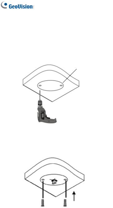
1.3.2 GV-EBD4711 / 8711 Installation
For Concealed Installation
1.Stick the drill template paster to the ceiling and drill three holes according to the drill template.
2.Insert the screw anchors.
8
Loading...