


 Loading...
GV-IP Speed Dome
User's Manual
Before attempting to connect or operate this product,
please read these instructions carefully and save this manual for future use. |
ISDV107-A-EN |
|
Preface
Welcome to the GV-IP Speed Dome User’s Manual.
There are two types of the GV-IP Speed Dome, Indoor and Outdoor. They are distinguished by model:
|
Application |
|
Model |
|
Firmware Version |
|
Indoor |
GV-SD220 (PoE) |
|
V1.07 |
|
|
|
|
|
|
|
|
Outdoor |
|
GV-SD220-S (PoE) |
|
|
|
|
|
|
||
|
|
|
|
|
|
|
Outdoor |
|
GV-SD2300 |
V1.07 |
|
|
|
|
|||
|
|
GV-SD2301 |
|||
|
|
|
|
|
|
|
|
|
|
|
|
This Manual provides an overview of the GV-IP Speed Dome and its accessories. The instructions will guide you through the installation and use of the GV-IP Speed Dome as well.
i

|
|
Contents |
|
Regulatory Notices................................................................................................... |
vi |
||
Note for Connecting to GV-System / GV-VMS ....................................................... |
vii |
||
Note for Recording ................................................................................................. |
viii |
||
Note for Installing Camera Outdoor ....................................................................... |
ix |
||
Optional Devices ...................................................................................................... |
x |
||
Chapter 1 |
Introduction........................................................................................... |
1 |
|
1.1 |
Overview............................................................................................................ |
….1 |
|
1.2 |
System Requirements............................................................................................. |
3 |
|
1.3 |
Packing List ............................................................................................................ |
4 |
|
|
1.3.1 Indoor GV-IP Speed Dome Camera (GV-SD220) ....................................... |
4 |
|
|
1.3.2 Outdoor GV-IP Speed Dome Camera (GV-SD220-S / GV-SD2300) ........... |
5 |
|
1.3.3 Outdoor GV-IP Speed Dome Camera (GV-SD2301)............................................... |
6 |
||
1.4 |
Functional Panel ..................................................................................................... |
7 |
|
|
1.4.1 Removing the Camera Cover ..................................................................... |
7 |
|
|
1.4.2 Camera Interior .......................................................................................... |
8 |
|
1.5 |
Installing the GV-IP Speed Dome.......................................................................... |
10 |
|
|
1.5.1 Indoor GV-IP Speed Dome: Hard-Ceiling Mount........................................ |
10 |
|
|
1.5.2 Outdoor GV-IP Speed Dome: Wall Pendant Mount.................................... |
12 |
|
1.6 |
Connecting the Camera ........................................................................................ |
20 |
|
|
1.6.1 Connecting the GV-PA901 PoE Adapter.................................................... |
22 |
|
Chapter 2 |
Getting Started.................................................................................... |
23 |
|
2.1 |
Looking Up the IP Address.................................................................................... |
23 |
|
2.2 |
Accessing Your Surveillance Images .................................................................... |
26 |
|
2.3 |
Configuring the Basics .......................................................................................... |
27 |
|
Chapter 3 Guest Mode and Live View Panel...................................................... |
28 |
||
3.1 |
The Live View Window.......................................................................................... |
29 |
|
3.2 |
The Control Panel of the Live View Window.......................................................... |
31 |
|
3.3 |
Snapshot of a Live Video ...................................................................................... |
32 |
|
3.4 |
Video Recording ................................................................................................... |
32 |
|
3.5 |
Picture-in-Picture and Picture-and-Picture View.................................................... |
33 |
|
3.6 |
Alarm Notification.................................................................................................. |
35 |
|
3.7 |
Video and Audio Configuration.............................................................................. |
36 |
|
3.8 |
Remote Configuration ........................................................................................... |
37 |
|
3.9 |
Camera Name Display.......................................................................................... |
37 |
|
3.10 |
Image Enhancement........................................................................................... |
37 |
|
3.11 |
PTZ Control......................................................................................................... |
38 |
|
ii |
|
|
|
3.12 |
Visual PTZ .......................................................................................................... |
39 |
3.13 |
I/O Control .......................................................................................................... |
41 |
3.14 |
Network Status.................................................................................................... |
41 |
Chapter 4 PTZ Control Panel .............................................................................. |
42 |
|
4.1 |
Preset Settings ..................................................................................................... |
45 |
4.2 |
Cruise Settings ..................................................................................................... |
46 |
4.3 |
Auto Pan Settings ................................................................................................. |
47 |
4.4 |
PTZ SettingsSequence Settings ......................................................................... |
48 |
4.5 |
PTZ SettingsTour Settings .................................................................................. |
50 |
4.6 |
Image SettingsWhite Balance............................................................................. |
52 |
4.7 |
Image SettingsAuto Exposure............................................................................. |
53 |
4.8 |
Image SettingsColor ........................................................................................... |
55 |
4.9 |
Image SettingsMask ........................................................................................... |
56 |
4.10 |
Image SettingsOther......................................................................................... |
58 |
4.11 |
PTZ SettingsSchedule ...................................................................................... |
60 |
4.12 |
PTZ Settings– Other ........................................................................................... |
61 |
4.13 |
System Configuration.......................................................................................... |
62 |
Chapter 5 Administrator Mode............................................................................ |
64 |
||
5.1 |
Video & Motion ..................................................................................................... |
66 |
|
|
5.1.1 |
Video Settings ........................................................................................... |
67 |
|
5.1.2 |
Motion Detection ....................................................................................... |
71 |
|
5.1.3 |
Text Overlay .............................................................................................. |
73 |
5.2 |
I/O Control ............................................................................................................ |
74 |
|
|
5.2.1 |
Input Settings ............................................................................................ |
74 |
|
5.2.2 |
Output Setting ........................................................................................... |
77 |
5.3 |
Events & Alerts...................................................................................................... |
78 |
|
|
5.3.1 |
E-mail........................................................................................................ |
79 |
|
5.3.2 |
FTP ........................................................................................................... |
81 |
|
5.3.3 |
Center V2.................................................................................................. |
83 |
|
5.3.4 |
VSM .......................................................................................................... |
85 |
|
5.3.5 |
Backup Center .......................................................................................... |
87 |
|
5.3.6 GV-Video Gateway / GV-Recording Server ............................................... |
89 |
|
|
5.3.7 |
ViewLog Server......................................................................................... |
91 |
|
5.3.8 |
RTSP / 3GPP ............................................................................................ |
92 |
5.4 |
Monitoring............................................................................................................. |
93 |
|
5.5 |
Recording Schedule.............................................................................................. |
94 |
|
|
5.5.1 |
Recording Schedule Settings .................................................................... |
94 |
|
5.5.2 |
I/O Monitoring Settings.............................................................................. |
95 |
iii

5.6 |
Remote ViewLog Player........................................................................................ |
96 |
|
5.7 |
Network ................................................................................................................ |
97 |
|
|
5.7.1 |
LAN Configuration..................................................................................... |
97 |
|
5.7.2 |
Advanced TCP/IP...................................................................................... |
99 |
|
5.7.3 |
IP Filter.................................................................................................... |
103 |
|
5.7.4 |
SNMP Settings........................................................................................ |
104 |
5.8 |
Management....................................................................................................... |
105 |
|
|
5.8.1 |
Date and Time Settings ........................................................................... |
105 |
|
5.8.2 |
Storage Settings...................................................................................... |
107 |
|
5.8.3 |
User Account........................................................................................... |
111 |
|
5.8.4 |
Log Information ....................................................................................... |
112 |
|
5.8.5 |
Tools........................................................................................................ |
113 |
|
5.8.6 |
Language ................................................................................................ |
115 |
Chapter 6 Recording and Playback................................................................... |
116 |
|
6.1 |
Recording ........................................................................................................... |
116 |
6.2 |
Playback ............................................................................................................. |
117 |
|
6.2.1 Playback Using the Memory Card ........................................................... |
117 |
|
6.2.2 Playback over Network............................................................................ |
121 |
|
6.2.3 Access to the Recorded Files through FTP Server .................................. |
121 |
|
6.2.4 Playback of Daylight Saving Time Events................................................ |
122 |
Chapter 7 Advanced Applications .................................................................... |
123 |
||
7.1 |
Upgrading System Firmware............................................................................... |
123 |
|
|
7.1.1 |
Using the Web Interface.......................................................................... |
124 |
|
7.1.2 Using the GV IP Device Utility ................................................................. |
125 |
|
7.2 |
Backing Up and Restoring Settings..................................................................... |
127 |
|
7.3 |
Restoring to Factory Default Settings.................................................................. |
129 |
|
7.4 |
Verifying Watermark............................................................................................ |
131 |
|
|
7.4.1 |
Accessing AVI Files ................................................................................. |
131 |
|
7.4.2 |
Running Watermark Proof ....................................................................... |
131 |
|
7.4.3 |
The Watermark Proof Window................................................................. |
132 |
7.5 |
Downloading Videos from the Memory Card ....................................................... |
133 |
|
|
7.5.1 Installing the GV-SDCardSync Utility ....................................................... |
133 |
|
|
7.5.2 |
The GV-SDCardSync Utility Window ....................................................... |
136 |
Chapter 8 DVR Configurations ......................................................................... |
137 |
|
8.1 |
Setting Up IP Cameras on GV-System................................................................ |
138 |
|
8.1.1 Customizing Camera Settings on GV-System ......................................... |
141 |
8.2 |
Remote Monitoring with Multi View ..................................................................... |
146 |
8.3 |
Remote Monitoring with E-Map........................................................................... |
148 |
iv
Chapter 9 CMS Configurations ......................................................................... |
150 |
|
9.1 |
Center V2 ........................................................................................................... |
150 |
9.2 |
Vital Sign Monitor................................................................................................ |
152 |
9.3 |
Dispatch Server .................................................................................................. |
153 |
Chapter 10 Smart Device Connection .............................................................. |
154 |
|
GV-IP Speed Dome Specifications ...................................................................... |
155 |
|
Appendix ........................................................................................................... |
163 |
|
A. The CGI Command................................................................................................. |
163 |
|
B. RTSP Protocol Support........................................................................................... |
164 |
|
C. Settings for Internet Explorer 8 ............................................................................... |
165 |
|
v
Regulatory Notices
FCC Notice
This equipment has been tested and found to comply with the limits for a Class A digital device, pursuant to part 15 of the FCC Rules. These limits are designed to provide reasonable protection against harmful interference when the equipment is operated in a commercial environment.
Class A
This equipment generates, uses, and can radiate radio frequency energy and, if not installed and used in accordance with the instruction manual, may cause harmful interference to radio communications. Operation of this equipment in a residential area is likely to cause harmful interference in which case the user will be required to correct the interference at their own expense.
CE Notice
This is a Class A product. In a domestic environment, this product may cause radio interference in which case the user may be required to take adequate measures.
RoHS Compliance
The Restriction of Hazardous Substances (RoHS) Directive is to forbid the use of hazardous materials of production. To meet the RoHS Directive requirements, this product is made to be RoHS compliant.
WEEE Compliance
This product is subject to the Waste Electrical and Electronic Equipment (WEEE) Directive and made compliant with the WEEE requirements.
vi
Naming Definition
|
GeoVision Analog and Digital Video Recording Software. The |
GV-System |
GV-System also refers to Multicam System, GV-NVR System, |
|
GV-DVR System and GV-Hybrid DVR System at the same time. |
GV-VMS |
GeoVision Video Management System for IP cameras. |
Note for Connecting to GV-System / GV-VMS
The GV-IP Speed Dome is designed to work with and record on GV-System / GV-VMS, a video management system.
1.By default, the images are recorded to the memory card inserted in the GV-IP Speed Dome.
2.Once the camera is connected to the GV-System / GV-VMS, the resolution set on the GV-System / GV-VMS will override the resolution set on the camera’s Web interface. You can only change the resolution settings through the Web interface when the connection to the GV-System / GV-VMS is interrupted.
vii

Note for Recording
1.By default, the images are recorded to the memory card inserted in the GV-IP Seed Dome.
2.Mind the following when using a memory card for recording:
•Recorded data on the memory card can be damaged or lost if the data are accessed while the camera is under physical shock, power interruption, memory card detachment or when the memory card reaches the end of its lifespan. No guarantee is provided for such causes.
•To avoid power outage, it is highly suggested to apply a battery backup (UPS).
•For better performance, it is highly suggested to use Micro SD card or SD card of MLC NAND flash, Class 10.
•Replace the memory card when its read/write speed is lower than 6 MB/s or when the memory card is frequently undetected by the camera.
viii
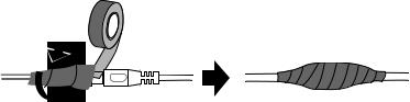
Note for Installing Camera Outdoor
When installing the GV-IP Speed Dome, be sure that any PoE, power, audio and I/O cables are waterproofed using waterproof silicon rubber or the like.
ix
Optional Devices
Optional devices can expand your camera’s capabilities and versatility. Contact your dealer for more information.
Device |
Description |
|
The GV-Mount Accessories provide a comprehensive |
|
lineup of accessories for installing the outdoor GV-IP |
GV-Mount Accessories |
Speed Dome on ceiling, wall corner and pole. For details, |
|
see GV-Mount Accessories Installation Guide on the |
|
Software CD. |
In-Ceiling Installation |
The in-ceiling package is used to install the indoor GV-IP |
Package |
Speed Dome by embedding the camera to the ceiling. |
|
|
|
The 24V DC power adapter is designed to convert AC 100V |
|
~ 240V 2.5A to DC 24V 3.75A and supply the power to |
Power Adapter |
indoor and outdoor GV-IP Speed Dome. The power |
|
adapter is available in the regions: AR, AU, EU, JU, UK, |
|
US. |
PA-901 PoE Adapter |
The GV-PA901 is a Power over Ethernet (PoE) adapter |
|
designed to provide power and network connection through |
|
a single Ethernet cable to outdoor GV-IP Speed Dome. |
GV-PoE Switch |
The GV-PoE Switch is designed to provide power along |
|
with network connection for IP devices. The GV-PoE |
|
Switch is available in various models with different numbers |
|
and types of ports. |
|
|
x

1 Introduction
Chapter 1 Introduction
1.1Overview
The GV-IP Speed Dome is a network PTZ camera designed for image quality and adaptability in various environments. This camera offers the image of 1080p at 30 fps, 720p at 60 fps and 20x / 30x optical zoom, capable of showing smooth live view with great detail. In low-light environments, image quality is promised with its image processing tools, such as IR cut filter (ICR), Wide Dynamic Range pro (WDR pro), Backlight Compensation and noise reduction.
Wide surveillance coverage is made possible with 360° endless panning and 180° tilting capacity. With GV-SD2301, it is up to 200° tilting angle. Dome movements such as Preset, Sequence, Auto Pan, Cruise and Tour can be programmed and activated by schedule. You can create multiple dome movement modes and have different modes enabled at different time slots. The GV-IP Speed Dome provides variable pan/tilt speeds ranging from a fast patrol of 400°/460° per second to a slow ramble of 0.5° per second with 0.2° pan accuracy for fast and accurate tracking ability.
GeoVision offers a complete series of GV-IP Speed Dome comes for indoor and outdoor use, and also optional mounting kits for outdoor installations on wall, ceiling and pole.
1

Features:
•1/2.8’’ progressive scan CMOS sensor
•Full HD 1080p at up to 30 fps and 720p at up to 60 fps
•20x / 30x optical zoom and 12x digital zoom
•Wide Dynamic Range Pro (WDR Pro)
•Day and night function with IR-cut filter
•2-way audio
•Vandal resistance (IK10 for metal and polycarbonate casing, GV-SD220-S / GV-SD2300
/GV-SD2301 only)
•Ingress protection (IP67 for GV-SD220-S / GV-SD2300 / GV-SD2301 only)
•Built-in SD card slot for local storage
•4 digital inputs, 1 relay output
•DC 24V / AC 24V / PoE + (IEEE 802.3at) for GV-SD220, PoE ++ (60 W) for GV-SD220-S
/GV-SD2300 and PoE ++ (50 W) for GV-SD2301
•Pan 360° endlessly
•Tilt from 0° to 180° for GV-SD220 / GV-SD220-S / GV-SD2300 and -20° to 220° for GV-SD2301
•Preset speed at up to 400°/sec for GV-SD220 and 460°/sec for GV-SD220-S / GV-2300 / GV-2301
•PTZ movement (Preset, Sequence, Auto Pan, Cruise and Tour)
•PTZ movement by schedule
•Auto and manual PTZ calibration
•Auto focus
•Backlight Compensation
•Image noise reduction
•Motion detection
•Privacy Mask
•Dual streams H.264 and MJEPG
•Smart phones & 3GPP support
•31 languages on Web interface
•ONVIF (Profile S) conformant
2

1 Introduction
1.2System Requirements
To access GV-IP Speed Dome functions through Web browser, ensure your PC is in good network connection and use one of the following web browsers:
•Microsoft Internet Explorer 7.x or later
•Google Chrome
•Mozilla Firefox
•Safari
Note:
1.For users of Internet Explorer 8, additional settings are required. For details, see
Appendix C.
2.With non-IE browsers,
A.Motion Detection, Text Overlay, two-way audio settings are not supported.
B.The Play function is only available on the live view window (Figure 3-2)
C.RTSP streaming must be kept as enabled. For more details, see 5.3.8 RTSP / 3GPP.
3
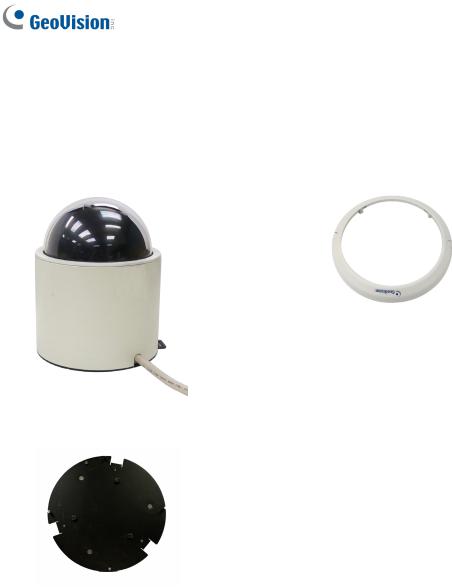
1.3Packing List
1.3.1 Indoor GV-IP Speed Dome Camera (GV-SD220)
• Indoor GV-IP Speed Dome |
• Hard-Ceiling Cover |
• Mounting Plate |
• GV-IP Speed Dome Software CD |
• GV-NVR Software DVD
4

1 Introduction
1.3.2 Outdoor GV-IP Speed Dome Camera (GV-SD220-S / GV-SD2300)
• Outdoor GV-IP Speed Dome |
• Pendant Tube |
• Hex Key x 2 |
• M6 Screw x 4 |
• |
Desiccant Pack x 4 |
• GV-IP Speed Dome Software CD |
• |
GV-NVR Software DVD |
|
5

1.3.3Outdoor GV-IP Speed Dome Camera (GV-SD2301)
• Outdoor GV-IP Speed Dome |
• Pendant Tube |
• Hex Key x 2 |
• Rubber ring |
• RJ-45 Connector |
• Desiccant Pack x 2 |
• Data Cable |
• GV-IP Speed Dome Software CD |
• GV-NVR Software DVD
6
1 Introduction
1.4Functional Panel
To access the functional panel of the GV-IP Speed Dome follow the section below to remove its camera cover first.
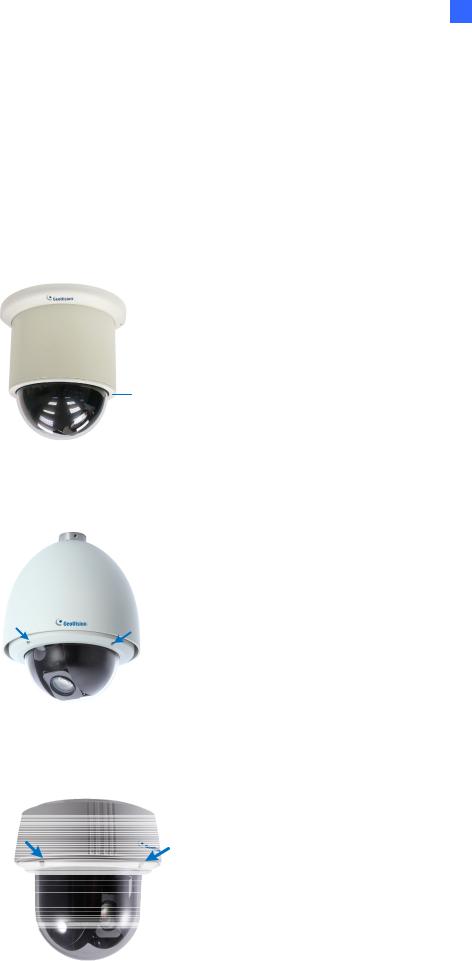
1.4.1 Removing the Camera Cover
•GV-SD220: Rotate to remove the camera cover.
camera cover
Figure 1-1
•GV-SD220S / GV-SD2300: Unscrew using the supplied hex key.
Figure 1-2
•GV-SD2300: Unscrew using the supplied hex key.
Figure 1-3
7

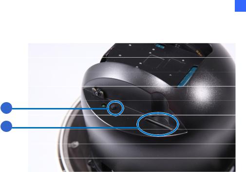
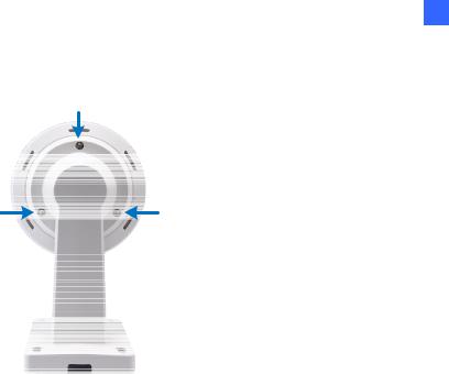
1.4.2 Camera Interior
1.4.2.1GV-SD220/ GV-SD220S / GV-SD2300
1
|
|
|
|
|
|
|
|
|
|
|
|
|
|
|
|
|
|
|
|
|
|
|
|
|
|
|
|
|
|
|
|
|
|
|
|
|
|
|
|
|
|
|
|
|
|
|
|
|
|
|
|
|
2 |
|
4 |
|
|
||
|
|
|
|
|
||||||||||
|
|
|
|
|
|
|
|
3 |
5 |
|
||||
|
|
|
|
|
|
|
|
|
|
|
|
|
|
|
|
|
|
|
6 |
|
|
|
|
|
|
||||
|
|
|
|
|
|
Figure 1-4 |
|
|
|
|
||||
|
|
|
|
|
|
|
|
|
|
|
||||
No. |
|
|
Name |
|
Function |
|
|
|
|
|||||
1. |
|
|
Default |
|
Restores all the settings to the factory default values. For details |
|||||||||
|
|
|
see 7.3 Restoring to Factory Default Settings. |
|||||||||||
|
|
|
|
|
||||||||||
|
|
|
|
|
|
|
||||||||
2. |
|
|
Status |
|
The status LED turns green when the power is on and fades |
|||||||||
|
|
|
when the camera is ready for use. |
|
|
|
|
|||||||
|
|
|
|
|
|
|
|
|
||||||
|
|
|
|
|
|
|
||||||||
3. |
|
|
Power |
|
The power LED turns green when the power is on. |
|||||||||
|
|
|
|
|
|
|||||||||
4. |
|
ACT |
|
The ACT LED flashes orange light upon data transmission. |
||||||||||
|
|
|
|
|
|
|
||||||||
5. |
|
|
Link |
|
The Link LED turns green with Internet connectivity. |
|||||||||
|
|
|
|
|
|
|||||||||
6. |
|
|
Memory Card Slot |
Insert a micro SD / SDHC card to store recording data. |
||||||||||
|
|
|
|
|
|
|
|
|
|
|
|
|
|
|
8
1 Introduction
1.4.2.2GV-SD2301
|
|
|
|
|
Figure 1-5 |
|
|
|
|
|
|
No. |
|
|
Name |
|
Function |
1. |
|
|
Default |
|
Restores all the settings to the factory default values. For details |
|
|
|
see 7.3 Restoring to Factory Default Settings. |
||
|
|
|
|
|
|
|
|
|
|
|
|
2. |
|
Memory Card Slot |
|
Insert a SD / SDHC card to store recording data. |
|
|
|
|
|
|
|
9
1.5Installing the GV-IP Speed Dome
1.5.1 Indoor GV-IP Speed Dome: Hard-Ceiling Mount
Required Items
• Indoor packing (supplied)
• ceiling screws x 3 (user-prepared)
Figure 1-6
1. Secure the mounting plate to the ceiling with self-prepared screws.
Figure 1-7
10
1 Introduction
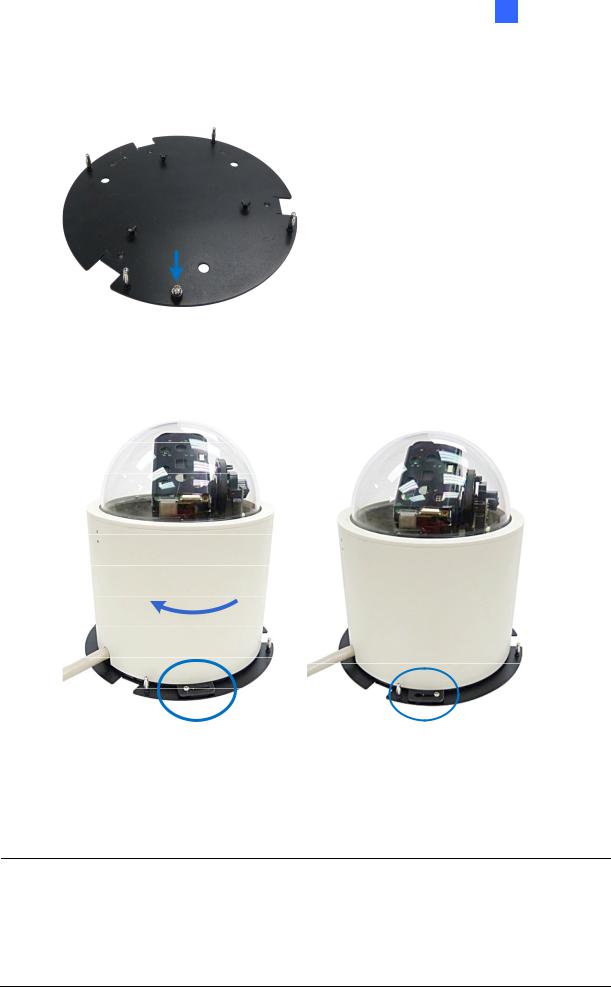
2.Secure the indoor GV-IP Speed Dome to the mounting plate. A. Loosen the screw on the mounting plate
Figure 1-8
B. Align the camera to the mounting plate and rotate the camera body to the right.
Figure 1-9
C.Tighten the screw.
3.Put on the hard-ceiling cover.
Note:
1.Cut away a side of the cover if you want to run the cable through.
2.You may also install the indoor GV-IP Speed Dome into the ceiling with optional mounting kits. For detail, see GV-Mount Accessories Installation Guide on the Software CD.
11
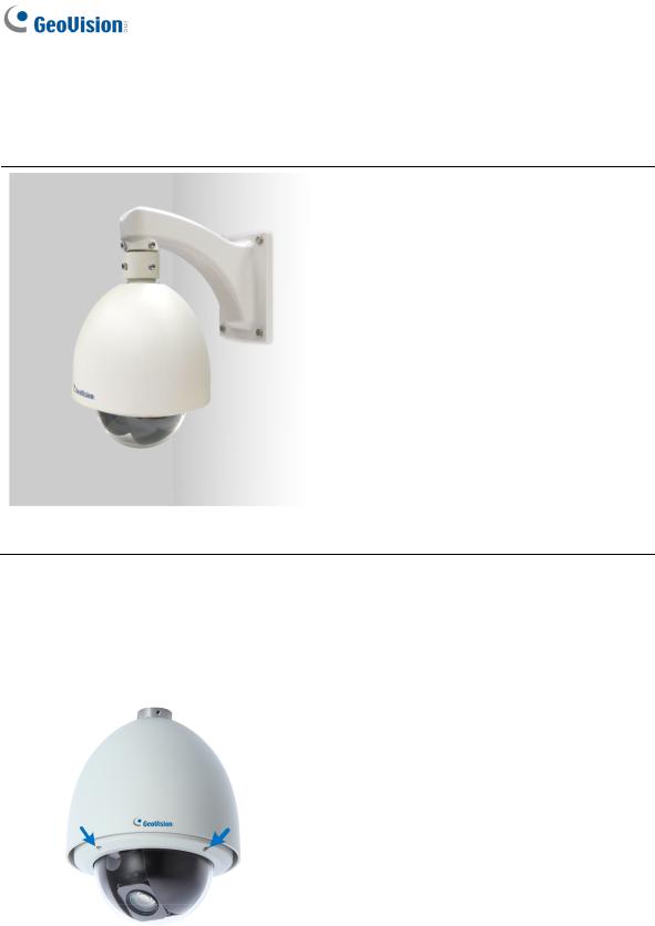
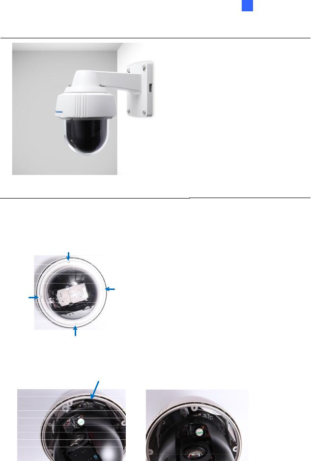
1.5.2Outdoor GV-IP Speed Dome: Wall Pendant Mount
1.5.2.1GV-SD220-S / GV-SD2300
Required Items
• Outdoor packing (supplied)
• Ceiling screws x 4 (user-prepared)
Figure 1-10
1.Insert the desiccants to the camera.
A. Remove the camera cover using the supplied hex key.
Figure 1-11
12

1 Introduction
B. Insert two desiccant packs to the indicated places.
Figure 1-12
IMPORTANT: Be sure to conceal the desiccants in the GV-IP Speed Dome within 2 minutes of opening the desiccant pack.
C.Insert your micro SD card into the memory card slot. See 1.4.2.1 GV-SD220/ GV-SD220S / GV-SD2300
D.Follow step 1A to secure the camera cover with the supplied hex key.
2.Assemble the camera with the pendant tube.
A.Thread the camera cable through the pendant tube.
B.Rotate the camera and lock it to the pendant tube.
Figure 1-13
13
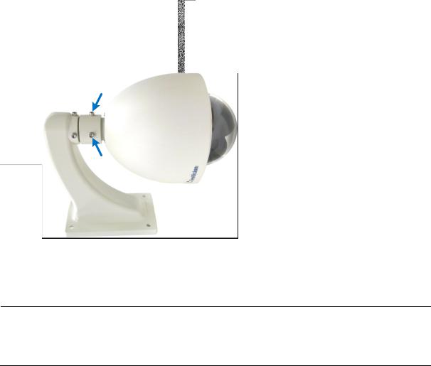
C. Secure the camera with the supplied M6 screws.
Figure 1-14
3. Secure the pendant tube to the wall with self-prepared screws.
Note: You may also install the camera to ceilings, wall corners (concave or convex), and poles using optional mounting kits. For details, see GV-Mount Accessories Installation Guide on the Software CD.
14
1 Introduction
1.5.2.2GV-SD2301
Required Items
• Outdoor packing (supplied)
• Ceiling screws x 4 (user-prepared)
Figure 1-15
1.Insert the desiccants to the camera.
A. Remove the camera cover using the supplied hex key.
Figure 1-16
B. Insert one desiccant pack to the indicated place.
Figure 1-17
15
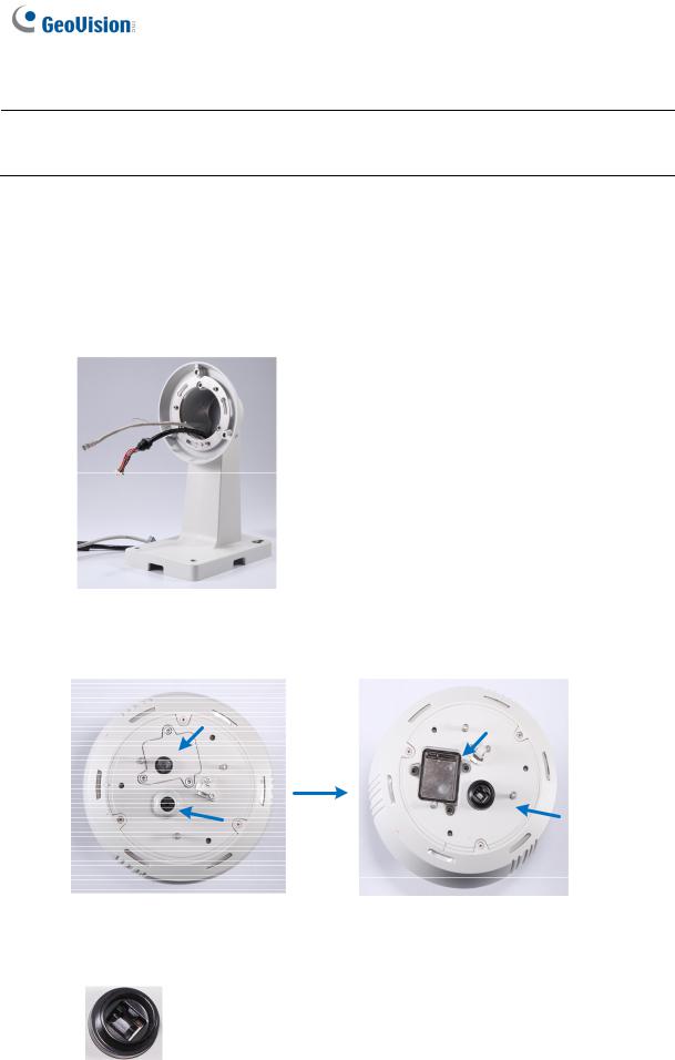
IMPORTANT: Be sure to conceal the desiccants in the GV-SD2301 within 2 minutes of opening the desiccant pack.
C.Insert your SD card into the SD card slot. See 1.4.2.2 GV-SD2301.
D.Secure the camera cover with the supplied hex key.
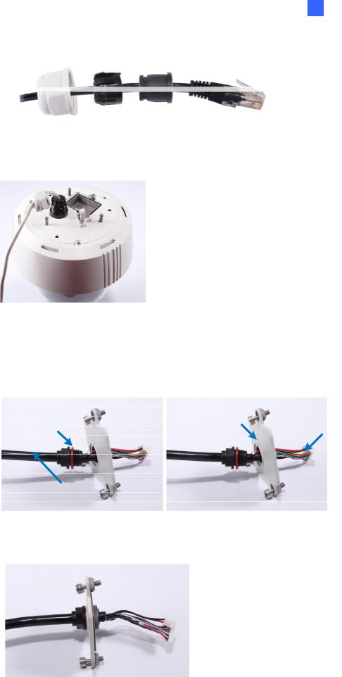
2.Connect the cables to the camera.
A.Thread the Ethernet cable and the data cable through the pendant tube.
Figure 1-18
B. Remove the cap and the mounting plate at the back of the camera.
Figure 1-19
C. Insert the Ethernet cable to the LAN port on the camera.
Figure 1-20
16
1 Introduction
D. Slide the cap and components through the Ethernet cable as shown below.
Figure 1-21
E. Move the cap and the components toward the LAN port.
Figure 1-22
F.Secure the cap tightly.
G.Slip the rubber ring on the Data Cable and then pass the pin connectors of the Data Cable through the mounting plate.
Figure 1-23
H. Fasten the data cable with the mounting plate and the rubber ring.
Figure 1-24
17
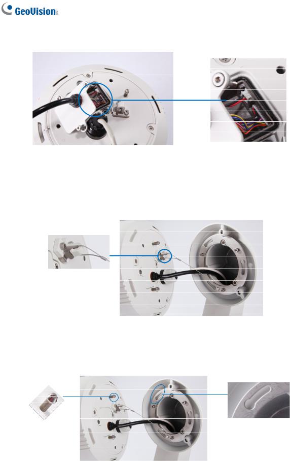
I.Insert the pin connectors of the Data Cable to the indicated area.
Figure 1-25
J.Secure the mounting plate with the supplied hex key.
3.Assemble the camera with the pendant tube.
A.Secure the safety lock.
Figure 1-26
B.Push the rivets into the holes on the pendant tube and rotate clockwise to lock the position.
Figure 1-27
18
C. Tighten the screws with the supplied hex key.
Figure 1-28
D. Secure the pendant tube to the wall with self-prepared screws.
1 Introduction
19
Loading...