


 Loading...
GV-Fisheye IP Camera H.264
User's Manual
Before attempting to connect or operate this product, |
|
please read these instructions carefully and save this manual for future use. |
FER12203V101-A |

© 2015 GeoVision, Inc. All rights reserved.
Under the copyright laws, this manual may not be copied, in whole or in part, without the written consent of GeoVision.
Every effort has been made to ensure that the information in this manual is accurate. GeoVision, Inc. makes no expressed or implied warranty of any kind and assumes no responsibility for errors or omissions. No liability is assumed for incidental or consequential damages arising from the use of the information or products contained herein. Features and specifications are subject to change without notice.
Note: No memory card slot or local storage function for Argentina.
GeoVision, Inc.
9F, No. 246, Sec. 1, Neihu Rd., Neihu District, Taipei, Taiwan Tel: +886-2-8797-8377
Fax: +886-2-8797-8335 http://www.geovision.com.tw
Trademarks used in this manual: GeoVision, the GeoVision logo and GV series products are trademarks of GeoVision, Inc. Windows and Windows XP are registered trademarks of Microsoft Corporation.
October 2015

Preface
Welcome to the GV-Fisheye IP Camera User’s Manual.
The GV-Fisheye IP Camera has the following models with different resolutions. This Manual is designed for the following models and firmware versions:
|
Model |
|
Model Number |
|
Firmware Version |
|
|
|
GV-FE2301 |
|
V3.0 |
|
|
|
|
|
|
|
Fisheye Camera |
|
GV-FE4301 |
|
|
|
|
|
|
||
|
|
|
|
|
|
|
|
GV-FE3402 / 3403 |
V3.03 |
||
|
|
|
|||
|
|
|
|
|
|
|
|
|
GV-FE5302 / 5303 |
V3.0 |
|
|
|
|
|
|
|
|
|
|
GV-FER3402 / 3403 |
|
V3.03 |
|
|
|
|
|
|
|
Fisheye Rugged Camera |
|
GV-FER521 |
|
V3.0 |
|
|
|
|
||
|
|
GV-FER5302 / 5303 |
|
||
|
|
|
|
|
|
|
|
|
|
|
|
|
|
|
GV-FER12203 |
|
V1.01 |
|
|
|
|
|
|
Note:
1.To upgrade the camera firmware from V2.07 or earlier to the latest version, back up the files in the camera’s memory card first before the upgrade and it is required to re-format the memory card after the upgrade.
2.Starting from V3.0, GV-Fisheye IP Camera (except GV-FER12203) supports recording to NAS devices using the Network Neighborhood settings.
i
Contents
Naming and Definition ........................................................... |
vii |
||
Note for Connecting to GV-System / GV-VMS .................... |
viii |
||
Note for Recording.................................................................. |
ix |
||
Note for USB Storage and WiFi Adapter ................................ |
x |
||
Note for Installing Camera...................................................... |
xi |
||
Chapter 1 |
Introduction .......................................................... |
1 |
|
1.1 |
Key Features ......................................................................................................... |
2 |
|
1.2 |
Packing List ........................................................................................................... |
5 |
|
1.3 |
System Requirement ............................................................................................ |
11 |
|
1.4 |
Optional Accessories ............................................................................................ |
12 |
|
1.5 |
Physical Description.............................................................................................. |
13 |
|
|
1.5.1 GV-FE2301 / 4301 and GV-FER521......................................................... |
13 |
|
|
1.5.2 GV-FE3402 / 3403 / 5302 / 5303 .............................................................. |
15 |
|
|
1.5.3 GV-FER3402 / 3403 / 5302 / 5303............................................................ |
16 |
|
|
1.5.4 |
GV-FER12203 .......................................................................................... |
19 |
1.6 |
Installation ............................................................................................................ |
20 |
|
|
1.6.1 |
Hard Ceiling Mount ................................................................................... |
21 |
|
1.6.2 |
In-Ceiling Mount........................................................................................ |
29 |
|
1.6.3 Standard Wall Mount and Ground Mount.................................................. |
32 |
|
|
1.6.4 |
Ground Mount........................................................................................... |
32 |
1.7 |
Connecting the GV-Fisheye Camera .................................................................... |
33 |
|
|
1.7.1 |
GV-FE2301 / 4301.................................................................................... |
33 |
|
1.7.2 |
GV-FER521 .............................................................................................. |
35 |
|
1.7.3 GV-FE3402 / 3403 / 5302 / 5303 .............................................................. |
36 |
|
|
1.7.4 Connecting PoE Converter and IR LED Ring for GV-FE3403 / 5303 ........ |
37 |
|
|
1.7.5 GV-FER3402 / 3403 / 5302 / 5303............................................................ |
40 |
|
|
1.7.6 |
GV-FER12203 .......................................................................................... |
42 |
ii
Chapter 2 Getting Started ................................................... |
43 |
|
2.1 |
Installing on a Network.......................................................................................... |
43 |
|
2.1.1 Checking the Dynamic IP Address............................................................ |
44 |
|
2.1.2 Assigning an IP Address........................................................................... |
46 |
|
2.1.3 Configuring the Wireless Connection ........................................................ |
48 |
2.2 |
Configuring the Basics .......................................................................................... |
51 |
Chapter 3 Accessing the Camera....................................... |
52 |
|
3.1 Accessing Your Surveillance Images .................................................................... |
52 |
|
3.2 Functions Featured on the Main Page .................................................................. |
53 |
|
3.2.1 |
The Live View Window.............................................................................. |
54 |
3.2.2 |
Fisheye View ............................................................................................ |
57 |
3.2.3 The Control Panel of the Live View Window ............................................. |
61 |
|
3.2.4 Snapshot of a Live Video .......................................................................... |
65 |
|
3.2.5 |
Video Recording ....................................................................................... |
65 |
3.2.6 Wide Angle Lens Dewarping..................................................................... |
66 |
|
3.2.7 |
Picture-in-Picture and Picture-and-Picture View........................................ |
67 |
3.2.8 |
Object Tracking......................................................................................... |
69 |
3.2.9 |
Alarm Notification...................................................................................... |
71 |
3.2.10 Video and Audio Configuration ............................................................... |
73 |
|
3.2.11 |
Remote Configuration............................................................................. |
75 |
3.2.12 |
Camera Name Display............................................................................ |
75 |
3.2.13 |
Image Enhancement............................................................................... |
75 |
3.2.14 |
I/O Control .............................................................................................. |
76 |
3.2.15 |
Visual Automation................................................................................... |
77 |
3.2.16 |
Network Status ....................................................................................... |
78 |
Chapter 4 |
Administrator Mode ........................................... |
79 |
|
4.1 |
Video & Motion ..................................................................................................... |
81 |
|
|
4.1.1 |
Video Settings .......................................................................................... |
82 |
|
4.1.2 |
Motion Detection....................................................................................... |
88 |
|
4.1.3 |
Privacy Mask ............................................................................................ |
90 |
|
4.1.4 |
Text Overlay ............................................................................................. |
91 |
|
4.1.5 |
Tampering Alarm ...................................................................................... |
92 |
|
4.1.6 |
Visual Automation..................................................................................... |
94 |
4.2 |
I/O Control ............................................................................................................ |
95 |
|
|
|
|
iii |
|
4.2.1 |
Input Settings............................................................................................ |
95 |
|
4.2.2 |
Output Settings......................................................................................... |
96 |
4.3 |
Events & Alerts ..................................................................................................... |
97 |
|
|
4.3.1 |
E-mail ....................................................................................................... |
97 |
|
4.3.2 |
FTP........................................................................................................... |
99 |
|
4.3.3 |
Center V2 ............................................................................................... |
102 |
|
4.3.4 |
Vital Sign Monitor.................................................................................... |
104 |
|
4.3.5 |
Backup Center........................................................................................ |
106 |
|
4.3.6 Video Gateway / Recording Server......................................................... |
108 |
|
|
4.3.7 |
ViewLog Server ...................................................................................... |
110 |
|
4.3.8 |
RTSP/ONVIF .......................................................................................... |
111 |
4.4 |
Monitoring........................................................................................................... |
113 |
|
4.5 |
Recording Schedule............................................................................................ |
114 |
|
|
4.5.1 |
Recording Schedule Settings.................................................................. |
114 |
|
4.5.2 |
I/O Monitoring Settings ........................................................................... |
115 |
4.6 |
Remote ViewLog ................................................................................................ |
116 |
|
4.7 |
Network .............................................................................................................. |
117 |
|
|
4.7.1 |
LAN ........................................................................................................ |
117 |
|
4.7.2 |
Wireless Client Mode.............................................................................. |
119 |
|
4.7.3 |
Advanced TCP/IP ................................................................................... |
121 |
|
4.7.4 |
UMTS Settings........................................................................................ |
125 |
|
4.7.5 |
IP Filtering .............................................................................................. |
127 |
|
4.7.6 |
SNMP Setting ......................................................................................... |
128 |
4.8 |
Management....................................................................................................... |
129 |
|
|
4.8.1 |
Date and Time Settings .......................................................................... |
129 |
|
4.8.2 |
Storage Settings ..................................................................................... |
131 |
|
4.8.3 |
User Account .......................................................................................... |
136 |
|
4.8.4 |
Log Information....................................................................................... |
137 |
|
4.8.5 |
Tools....................................................................................................... |
139 |
|
4.8.6 |
Language................................................................................................ |
141 |
Chapter 5 Recording and Playback ................................. |
142 |
|
5.1 |
Recording ........................................................................................................... |
142 |
5.2 |
Playback ............................................................................................................. |
143 |
|
5.2.1 Playback from the Memory Card............................................................. |
143 |
|
5.2.2 Playback over Network ........................................................................... |
148 |
|
5.2.3 Access to the Recorded Files through FTP Server ................................. |
149 |
|
5.2.4 Playback of Daylight Saving Time Events............................................... |
150 |
iv |
|
|
Chapter 6 |
Advanced Applications ................................... |
151 |
|
6.1 |
Upgrading System Firmware............................................................................... |
151 |
|
|
6.1.1 |
Using the Web Interface ......................................................................... |
153 |
|
6.1.2 Using the GV-IP Device Utility ................................................................ |
154 |
|
6.2 |
Backing Up and Restoring Settings..................................................................... |
156 |
|
|
6.2.1 Backing Up the Settings.......................................................................... |
156 |
|
|
6.2.2 |
Restoring the Settings............................................................................. |
157 |
6.3 |
Restoring to Factory Default Settings.................................................................. |
158 |
|
|
6.3.1 |
Using the Web Interface ......................................................................... |
158 |
|
6.3.2 Directly on the Camera ........................................................................... |
158 |
|
6.4 |
Changing Password............................................................................................ |
161 |
|
6.5 |
Verifying Watermark ........................................................................................... |
163 |
|
|
6.5.1 |
Accessing AVI Files ................................................................................ |
163 |
|
6.5.2 |
Running Watermark Proof ...................................................................... |
163 |
|
6.5.3 |
The Watermark Proof Window ................................................................ |
164 |
6.6 |
Downloading Videos from the Micro SD Card ..................................................... |
165 |
|
|
6.6.1 Installing the GV-SDCardSync Utility ...................................................... |
165 |
|
|
6.6.2 |
The GV-SDCardSync Utility Window ...................................................... |
168 |
Chapter 7 DVR Configurations ......................................... |
169 |
|
7.1 |
Setting Up IP Cameras on GV-System ............................................................... |
171 |
|
7.1.1 Customizing the Basic Settings on GV-System....................................... |
174 |
7.2 |
Setting Up IP Cameras on GV-VMS ................................................................... |
175 |
7.3 |
Remote Monitoring with Multi View ..................................................................... |
178 |
|
7.3.1 Connecting to the IP Camera.................................................................. |
178 |
7.4 |
Remote Monitoring with E-Map........................................................................... |
179 |
|
7.4.1 Creating an E-Map for the IP Camera..................................................... |
179 |
|
7.4.2 Connecting to the IP Camera.................................................................. |
180 |
Chapter 8 CMS Configurations......................................... |
181 |
|
8.1 |
Center V2 ........................................................................................................... |
181 |
8.2 |
Vital Sign Monitor................................................................................................ |
184 |
8.3 |
Dispatch Server .................................................................................................. |
185 |
v
Appendix 187 |
|
A. Settings for Internet Explore 8 or later..................................................................... |
187 |
B. RTSP Protocol Support........................................................................................... |
188 |
C. The Supported Mobile Broadband Devices............................................................. |
189 |
D. The CGI Command................................................................................................. |
190 |
E. Supported Firmware for Flash Memory ................................................................... |
191 |
vi
Naming and Definition
GeoVision Analog and Digital Video Recording Software. The GV-
GV-System System also refers to Multicam System, GV-NVR System, GVHybrid DVR System and GV-DVR System at the same time.
GV-VMS |
GeoVision Video Management System for IP cameras. |
|
|
vii

Note for Connecting to GV-System / GV-VMS
The GV-Fisheye IP Camera is designed to work with GV-System / GV-VMS, a video management system. Note the following when the camera is connected to GV-System / GVVMS:
1.By default, the images are recorded to the memory card inserted in the GV-Fisheye IP Camera.
2.Once the camera is connected to the GV-System / GV-VMS, the resolution set on the GV-System / GV-VMS will override the resolution set on the camera’s Web interface. You can only change the resolution settings through the Web interface when the connection to the GV-System / GV-VMS is interrupted.
viii
Note for Recording
1.By default, the images are recorded to the memory card inserted in the GV-Fisheye IP Camera. Make sure the Write recording data into local storage option (see 4.1.1 Video Settings) is enabled. If this option is disabled, the camera will stop recording to the memory card while the live view is accessed through Web browsers or other applications.
2.Mind the following when using a memory card for recording:
•Recorded data on the memory card can be damaged or lost if the data are accessed while the camera is under physical shock, power interruption, memory card detachment or when the memory card reaches the end of its lifespan. No guarantee is provided for such causes.
•The stored data can be lost if the memory card is not accessed for a long period of time. Back up your data periodically if you seldom access the memory card.
•Memory cards are expendable and their durability varies according to the conditions of the installed site and how they are used. Back up your data regularly and replace the memory card annually.
•To avoid power outage, it is highly suggested to apply a battery backup (UPS).
•For better performance, it is highly suggested to use Micro SD card of MLC NAND flash, Class 10.
•Replace the memory card when its read/write speed is lower than 6 MB/s or when the memory card is frequently undetected by the camera.
3.It is recommended to use memory cards of the following setting and specifications:
•Apply a battery backup (UPS) to avoid power outage.
•Use Micro SD card of MLC NAND flash, Class 10 for better performance.
ix

Note for USB Storage and WiFi Adapter
Mind the following limitations and requirements for using USB storage and GV-WiFi Adapter:
1.The USB hard drive must be of 2.5’’ or 3.5’’, version 2.0 or above.
2.The USB hard drive’s storage capacity must not exceed 2TB.
3.USB flash drives and USB hubs are not supported.
4.External power supply is required for the USB hard drive.
5.To connect a GV-WiFi Adapter, make sure it is connected before the camera is powered on.
x
Note for Installing Camera
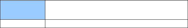
When installing GV-FER outdoor models, be sure that:
1.The camera is set up above the junction box to prevent water from entering the camera along the cables.
2.Any PoE, power, audio and I/O cables are waterproofed using waterproof silicon rubber or the like.
3. The screws are tightened and the cover is in place after opening the camera cover.
xi
4.The silica gel bag loses it effectiveness when the dry camera is opened. To prevent the lens from fogging up, use the supplied adhesive tap and replace the silica gel bag every time you open the camera, and conceal the gel bag in camera within 2 minutes of exposing to open air.
When installing GV-FE indoor models, be sure to:
•Keep the indoor camera shielded from rain and moisture.
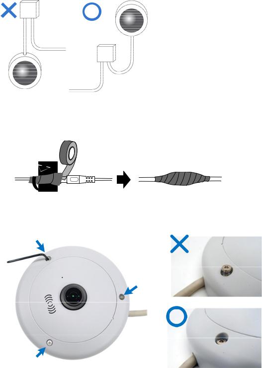
When installing GV-FE or GV-FER models with IR LED rings, be sure that:
•An operating IR LED ring may reach high temperatures of up to 60°C (140°F). Disconnect the power supply and allow the IR LED ring to cool down before handling the device.
xii

1 Introduction
Chapter 1 Introduction
The fisheye camera allows you to monitor all angles of a location using just one camera. It can be installed to the ceiling, wall, wall corner and pole. The distorted hemispherical image of the fisheye camera will be converted into the conventional rectilinear projection.
Without installing any software, you can watch live view and utilize functions such as motion detection, privacy mask, and alert notification through the Web interface. In addition, GVFisheye IP Camera seamlessly integrates with the GV-System / GV-VMS, providing advanced monitoring and video management features.
The following GV-Fisheye Cameras are available:
|
Models |
|
|
Type |
|
Description |
|
|
GV-FE2301 / 4301 |
|
|
|
|
2 MP / 4 MP |
|
|
|
|
|
|
|
|
|
|
GV-FE3402 / 5302 |
|
|
Indoor |
3 MP WDR Pro / 5 MP |
||
|
|
|
|
|
|
|
|
|
GV-FE3403 / 5303 |
|
|
|
|
3 MP WDR Pro / 5 MP, IR LED ring |
|
|
|
|
|
|
|
|
|
|
GV-FER521 |
|
|
|
5 |
MP, IP66, IK10 for metal casing |
|
|
|
|
|
|
|
|
|
|
GV-FER3402 / 5302 |
|
|
|
3 |
MP WDR Pro / 5 MP, IP67, IK10+ for |
|
|
|
|
|
|
metal casing |
||
|
|
|
|
Outdoor |
|
||
|
|
|
|
|
|
|
|
|
GV-FER3403 / 5303 |
|
|
3 |
MP WDR Pro / 5 MP, IR LED ring, IP67, |
||
|
|
|
|
|
IK10+ for metal casing |
||
|
|
|
|
|
|
||
|
|
|
|
|
|
|
|
|
GV-FER12203 |
|
|
|
|
12 MP, IR LED, IP 67, IK10+ for metal |
|
|
|
|
|
|
casing |
||
|
|
|
|
|
|
||
|
|
|
|
|
|
|
|
1
1.1 Key Features
• Image sensor
Camera Model |
Image Sensor |
|
|
GV-FE2301
GV-FE4301
1/2.5’’ progressive scan CMOS
GV-FE5302 / 5303 GV-FER521 / 5302 / 5303
GV-FE3402 / 3403
1/3.2’’ progressive scan CMOS
GV-FER3402 / 3403
GV-FER12203 |
1/1.7’’ progressive scan CMOS |
|
|
•Dual streams from H.264 or MJPEG
•Frame rate
|
Camera Model |
|
|
Frame Rate |
|
|
|
|
|
|
GV-FE2301 |
|
|
Up to 15 fps at 1440 x1376 |
|
|
|
|
|
|
GV-FE3402 / 3403 |
|
|
Up to 15 fps at 2048 x 1536 |
|
GV-FER3402 / 3403 |
|
|
|
|
|
|
|
|
|
|
|
|
|
|
GV-FE4301 |
|
|
Up to 15 fps at 2048 x 1944 |
|
|
|
|
|
|
GV-FE5302 / 5303 |
|
|
Up to 10 fps at 2560 x 1920 |
|
GV-FER521 / 5302 / 5303 |
|
|
|
|
|
|
|
|
|
|
|
|
|
|
GV-FER12203 |
|
|
Up to 15 fps at 4000 x 3000 |
|
|
|
|
|
2

1 Introduction
• Day and night function
Camera Model |
Day / Night function |
|
|
GV-FE2301 / 4301
Electronic
GV-FER521
GV-FE3402 / 3403
GV-FE5302 / 5303
GV-FER3402 / 3403 Removable IR-cut filter
GV-FER5302 / 5303
GV-FER12203
•Effective distance of IR LED
-Up to 10 m / 32.81 ft (GV-FE3403 / 5303 and GV-FER3403 / 5303 only)
-Up to 30 m / 98.43 ft (GV-FER12203)
•Wide Dynamic Range
-WDR for GV-FE5302 / 5303 and GV-FER5302 / 5303
-WDR Pro for GV-FE3402 / 3403 and GV-FER3402 / 3403
•Defog (Except GV-FER12203)
•Ingress protection rating
-IP66 rating (GV-FER521 only)
-IP67 rating (GV-FER3402 / 3403 / 5302 / 5303 / 12203 only)
•Vandal Resistance Rating
-IK10 rating for metal casing (GV-FER521 only)
-IK10+ for metal casing (GV-FE3402 / 3403 / 5302 / 5303 and GV-FER3402 / 3403 / 5302 / 5303 / 12203 only)
•2D noise reduction
•Low lux enhancement (GV-FER12203 only)
•EN50155 compliance for rolling stock applications (GV-FER521 only)
•Built-in micro SD card slot (SD/SDHC) for local storage
•Audio
-Built-in microphone and speaker (Except GV-FER12203)
-Built-in microphone and 1 stereo phone jack for external speaker (GV-FER12203)
•Mini USB slot for WiFi adapter or USB hard drive (GV-FE3402 / 3403 / 5302 / 5303)
•USB slot for WiFi adapter (GV-FER12203)
3
•One sensor input and alarm output (GV-FE2301 / 4301 only and GV-FER12203)
•Digital Object Tracking
•Virtual PTZ function
•Auto Pan function
•Provides 360° and 180° panorama view
•No mechanical moving parts
•Different angle of view controllable by multiple users at the same time
•Playback from any view angle and zoom level
•Privacy mask
•Visual automation
•Tampering alarm
•Text overlay
•31 languages on Web interface
•ONVIF (Profile S) conformant
Note: GV-FER12203 currently does not support micro SD cards and USB storage devices.
4
1 Introduction
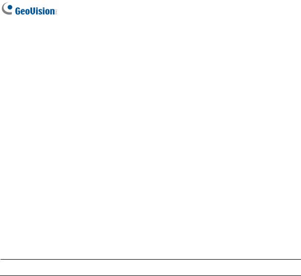
1.2 Packing List
GV-FE2301 / 4301 and GV-FER521
• Fisheye Camera |
• Support Bracket x 3 |
• Camera Cover (Hard Ceiling Mount) |
• Camera Cover (In-Ceiling Mount) |
• Screw (Hard Ceiling Mount) x 3 |
• Screw (In-Ceiling Mount) x 3 |
• Torx Wrench |
• Plastic Screw Anchor x 3 |
•Installation Sticker
•For GV-FE2301 / 4301 only:
-3-Pin or 2-Pin Terminal Block
-DC 12V Power Adapter
•For GV-FER521 only:
-Cable Connector
-Silica Gel Bag and Adhesive Tape x 2
•GV-IPCAM H.264 Software DVD
•GV-NVR Software DVD
•Warranty Card
5
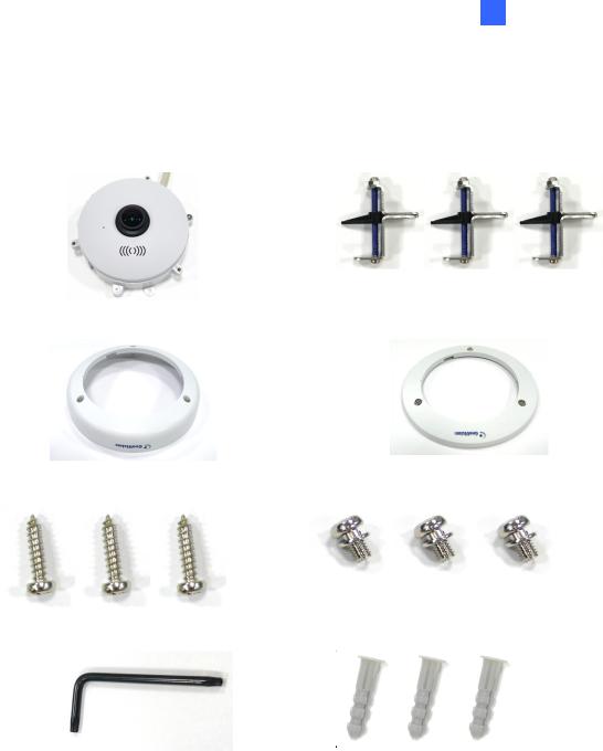
GV-FE3402 / 5302 and GV-FE3403 / 5303
• Fisheye Camera |
• Support Bracket x 3 |
• Camera Cover (Hard Ceiling Mount) |
• Camera Cover (In-Ceiling Mount) |
• Screw (Hard Ceiling Mount) x 3 |
• Screw (In-Ceiling Mount) x 3 |
• Torx Wrench |
• Plastic Screw Anchor x 3 |
• Mini USB Extension Cable |
• IR LED Ring (GV-FE3403 / 5303 only) |
6
1 Introduction
•PoE Converter set (including 1 module, 1 DC Power Y-cable, 1 RJ-45 cable and 3 PoE Screws) (GV-FE3403 / 5303 only)
• Installation Sticker
•Power Adapter
•GV-IPCAM H.264 Software DVD
•GV-NVR Software DVD
•GV-Fisheye IP Dome Hardware Installation Guide
•Warranty Card
Note: The power adapter can be excluded upon request.
7
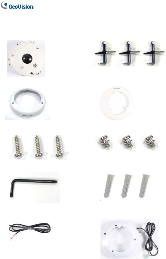
GV-FER3402 / 5302 and GV-FER3403 / 5303
• Fisheye Camera |
• Support Bracket x 3 |
• Camera Cover (Hard Ceiling Mount) |
• Camera Cover (In-Ceiling Mount) |
• Screw (Hard Ceiling Mount) x 3 |
• Screw (In-Ceiling Mount) x 3 |
• Torx Wrench |
• Plastic Screw Anchor x 3 |
• IR LED Ring (GV-FER3403 / 5303 only) |
• Waterproof Rubber |
8
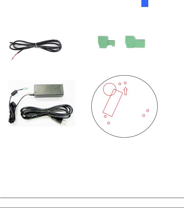
1 Introduction
• Power Cable |
• Terminal Block x 2 |
|
(female) |
(male) |
• IR Power Adapter (DC 12V, 3.5A, GV- |
• Installation Sticker |
|
FER3403 / 5303 only) |
|
|
• Silica Gel Bag and Adhesive Tape x 2 |
• Cable Connector |
•Power Adapter (DC 12V, 1.25A)
•GV-IPCAM H.264 Software DVD
•GV-NVR Software DVD
•GV-Fisheye IP Dome Hardware Installation Guide
•Warranty Card
Note: The power adapter can be excluded upon request.
9
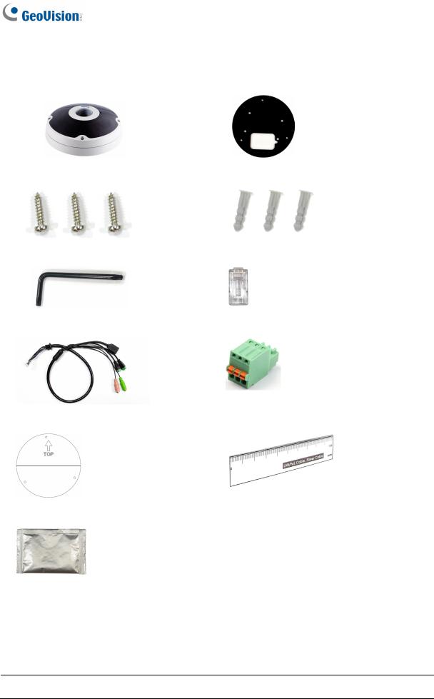
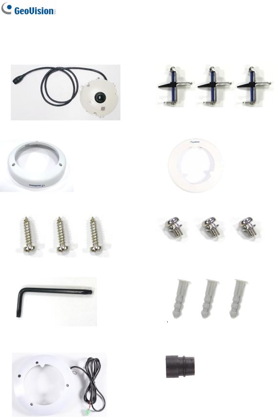
GV-FER12203
• Fisheye Camera |
• Back Plate |
• Plate Screw x 3 |
• Plastic Screw Anchor x 3 |
• Torx Wrench |
• RJ-45 Connector |
• Data Cable |
• Terminal Block |
• Installation Sticker |
• Ruler |
•Silica Gel Bag x 2
•Power Adapter
•GV-IPCAM H.264 Software DVD
•GV-NVR Software DVD
•Warranty Card
Note: The power adapter can be excluded upon request.
10

1 Introduction
1.3 System Requirement
To operate the camera through a web browser, make sure your PC has good network connection, and meet the following system requirement:
OS |
64-bit |
Windows 7 / 8 / 8.1 / Server 2008 R2 / Server 2012 R2 |
|
GV-VMS |
V14.1 or later |
||
GV-System Version |
V8.5.9.0 with patch files or later versions |
||
Browser |
• Internet Explorer 7.x or later |
||
|
|
• |
Firefox |
|
|
• |
Google Chrome |
|
|
• |
Safari |
Note:
1.If you are using Microsoft Internet Explorer 8.0 or later, additional settings are required. Refer to Settings for Internet Explorer 8 or later in Appendix A.
2.When using non-IE browsers,
a.The following functions are not supported: Motion Detection, Tampering Alarm, Visual Automation, Text Overlay, and Two-Way Audio. To see the functions available on live view windows using non-IE browsers, see Figure 3-4.
b.RTSP streaming must be enabled. By default, RTSP streaming is enabled. See 4.3.8 RTSP to see more details on RTSP settings.
To access GV-FER12203 images, the following PC specifications should be met:
CPU |
Intel Core i5-4670, 3.40 GHz |
Memory |
DDR3 8 GB RAM |
On Board Graphics |
Intel HD Graphics 4600 (Versions of driver from year 2014 or later |
|
required) |
11

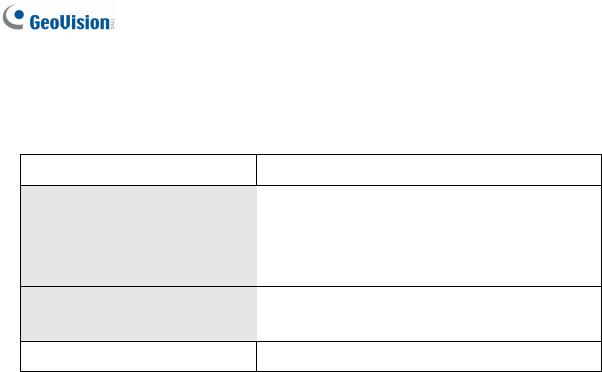
1.4 Optional Accessories
Optional devices can expand the capabilities and versatility of your GV-Fisheye Camera. Contact your dealer for more information.
|
Name |
|
Details |
|
|
|
|
|
GV-PA191 |
|
The GV-PA191 is a Power over Ethernet (PoE) adapter |
|
Power over Ethernet (PoE) |
|
designed to provide power to the IP device through a single |
|
|
Ethernet cable. |
|
|
Adapter |
|
|
|
|
|
|
|
|
|
|
|
GV-Mount Accessories |
|
The GV-Mount Accessories provides a comprehensive |
|
|
|
lineup of accessories for installation on ceiling, wall and |
|
|
|
pole. For details, see GV-Mount Accessories Installation |
|
|
|
Guide online. |
|
|
|
|
|
GV-WiFi Adapter |
|
The GV-WiFi Adapter is a plug-and-play device that provides |
|
|
|
WiFi connectivity to GV-IP Cameras through a mini USB |
|
|
|
port. This product complies with IEEE 802.11 b/g/n (Draft |
|
|
|
3.0) standards for wireless networking. |
|
|
|
|
|
GV-POE Switch |
|
The GV-POE Switch is designed to provide power along with |
|
|
|
network connection for IP devices. The GV-POE Switch is |
|
|
|
available in various models with different numbers and types |
|
|
|
of ports. |
|
|
|
|
|
Power Adapter |
|
Contact your sales representative for the countries and |
|
|
|
areas supported. |
|
|
|
|
12
1 Introduction
1.5 Physical Description
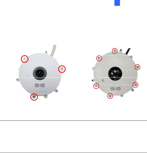
1.5.1 GV-FE2301 / 4301 and GV-FER521
To access the Default button, LED indicators and micro SD card slot, unscrew the screws indicated below and then remove the camera cover.
Figure 1-1a: GV-FE2301 / 4301 |
Figure 1-1b: GV-FER521 |
Note: For GV-FER521, a silica gel bag is attached to the inside of the camera cover. The silica gel loses effectiveness after you open the camera cover. To prevent the lens from fogging up, it is highly recommended to replace the silica gel bag every time you open the camera. To replace the silica gel bag, use the supplied adhesive tape to attach a new silica gel bag and fasten the camera cover within 2 minutes of opening the silica gel bag package.
13

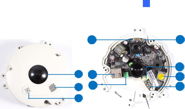
You can now access the Load Default button, LED indicators, and the micro SD card slot.
5
6 |
1 |
|
2 |
7 |
3 |
8 |
4 |
|
Figure 1-2a: GV-FE2301 / 4301
1
2
3
6 |
5 |
7 |
8 |
4 |
|
|
|
|
|
Figure 1-2b: GV-FER521 |
|
|
|
|
|
|
No. |
|
|
Name |
|
Function |
|
|
|
|
|
|
1 |
|
|
Lens |
|
Receives image inputs. |
|
|
|
|
|
|
2 |
|
|
Speaker |
|
Talks to the surveillance area from the local computer. |
|
|
|
|
|
|
3 |
|
|
Microphone |
|
Receives the sound from the camera. |
|
|
|
|
|
|
4 |
|
|
Default Button |
|
Resets all configurations to default factory settings. See 6.3 |
|
|
|
Restoring to Factory Default Settings. |
||
|
|
|
|
|
|
|
|
|
|
|
|
5 |
|
|
Micro SD Card Slot |
|
Inserts a micro SD / SDHC memory card to store recorded data. |
|
|
|
|
|
|
6 |
|
|
Network status LED |
|
Indicates the network status. |
|
|
|
|
|
|
7 |
|
|
Power status LED |
|
Indicates whether the camera is powered on or off. |
|
|
|
|
|
|
8 |
|
|
System status LED |
|
Indicates whether the system is booted successfully or not. |
|
|
|
|
|
|
Note: SDXC and UHS-I card types are not supported.
14
1 Introduction
1.5.2 GV-FE3402 / 3403 / 5302 / 5303
4 |
7 |
|
|
8 |
1 |
5 |
9 |
|
|
|
2 |
6 |
10 |
3 |
|
|
|
|
|
|
|
Figure 1-3 |
|
|
|
|
|
|
No. |
|
|
Name |
|
Function |
|
|
|
|
|
|
1. |
|
|
Lens |
|
Receives image inputs. |
|
|
|
|
|
|
2. |
|
|
Speaker |
|
Talks to the surveillance area from the local computer. |
|
|
|
|
|
|
3. |
|
|
Microphone |
|
Receives the sound from the camera. |
|
|
|
|
|
|
4. |
|
|
Status LED |
|
Indicates whether the device is booted successfully or not. |
|
|
|
|
|
|
5. |
|
|
LAN / PoE |
|
Connects to a 10/100 Ethernet or PoE. |
|
|
|
|
|
|
6. |
|
|
Terminal Block |
|
Connects to power. |
|
|
|
|
|
|
7. |
|
|
Default Button |
|
Resets all configurations to default factory settings. See 6.3 |
|
|
|
Restoring to Factory Default Settings. |
||
|
|
|
|
|
|
|
|
|
|
|
|
8. |
|
|
Audio Out |
|
Connects to an external speaker for broadcast. |
|
|
|
|
|
|
9. |
|
|
Micro SD Card Slot |
|
Inserts a micro SD / SDHC memory card to store recorded |
|
|
|
data. |
||
|
|
|
|
|
|
|
|
|
|
|
|
10. |
|
|
Mini USB Slot |
|
Connects to a GV-WiFi Adapter or a USB hard drive for |
|
|
|
external storage. |
||
|
|
|
|
|
|
|
|
|
|||
Note: SDXC and UHS-I card types are not supported. |
|||||
|
|
|
|
|
|
15
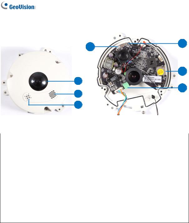
1.5.3 GV-FER3402 / 3403 / 5302 / 5303
4 |
5 |
|
6
1
7
2
3
|
|
|
|
|
Figure 1-4 |
|
|
|
|
|
|
No. |
|
|
Name |
|
Function |
|
|
|
|
|
|
1. |
|
|
Lens |
|
Receives image inputs. |
|
|
|
|
|
|
2. |
|
|
Speaker |
|
Talks to the surveillance area from the local computer. |
|
|
|
|
|
|
3. |
|
|
Microphone |
|
Receives the sound from the camera. |
|
|
|
|
|
|
4. |
|
|
LEDs |
|
See the table below for details. |
|
|
|
|
|
|
5. |
|
|
Default Button |
|
Resets all configurations to default factory settings. See 6.3 |
|
|
|
Restoring to Factory Default Settings. |
||
|
|
|
|
|
|
|
|
|
|
|
|
6. |
|
|
Micro SD Card Slot |
|
Inserts a micro SD / SDHC memory card to store recorded |
|
|
|
data. |
||
|
|
|
|
|
|
|
|
|
|
|
|
7. |
|
|
Terminal Block |
|
Connects to power. |
|
|
|
|
|
|
Note: SDXC and UHS-I card types are not supported.
16
Loading...