


 Loading...
GV-Control Center
User's Manual V3.6.0
CCV36-A

© 2019 GeoVision, Inc. All rights reserved.
Under the copyright laws, this manual may not be copied, in whole or in part, without the written consent of GeoVision.
Every effort has been made to ensure that the information in this manual is accurate. GeoVision, Inc. makes no expressed or implied warranty of any kind and assumes no responsibility for errors or omissions. No liability is assumed for incidental or consequential damages arising from the use of the information or products contained herein. Features and specifications are subject to change without notice.
GeoVision, Inc.
9F, No. 246, Sec. 1, Neihu Rd., Neihu District, Taipei, Taiwan Tel: +886-2-8797-8377
Fax: +886-2-8797-8335 http://www.geovision.com.tw
Trademarks used in this manual: GeoVision, the GeoVision logo and GV series products are trademarks of GeoVision, Inc.
July 2019
Contents
Naming and Definition ........................................................................................................ |
v |
||
GDPR Practice..................................................................................................................... |
v |
||
GPU Decoding Specifications ............................................................................................ |
vi |
||
Chapter 1 |
Introduction...................................................................................................... |
1 |
|
1.1 |
Minimum System Requirements ................................................................................. |
2 |
|
|
1.1.1 |
Software License................................................................................................................. |
3 |
1.1.2 Supported GeoVision IP Devices and Software .................................................................. |
3 |
||
1.2 |
Options ....................................................................................................................... |
4 |
|
1.3 |
Overview..................................................................................................................... |
5 |
|
|
1.3.1 The Control Center Main Window....................................................................................... |
5 |
|
1.3.2 |
The Toolbar.......................................................................................................................... |
6 |
|
1.3.3 |
The Host List ....................................................................................................................... |
8 |
|
1.3.4 |
The Group List ..................................................................................................................... |
9 |
|
Chapter 2 |
Getting Started................................................................................................ |
10 |
|
2.1 |
Installation ................................................................................................................. |
10 |
|
2.2 |
Hosts and Groups...................................................................................................... |
11 |
|
|
2.2.1 |
Creating a Host ................................................................................................................. |
12 |
2.2.2 |
Creating a Group ............................................................................................................... |
13 |
|
2.3 |
Connecting to Control Center..................................................................................... |
14 |
|
|
2.3.1 The Control Center Server Window .................................................................................. |
15 |
|
2.3.2 |
Advanced Settings............................................................................................................. |
16 |
|
Chapter 3 |
Live Video........................................................................................................ |
18 |
|
3.1 |
Live View ................................................................................................................... |
18 |
|
3.1.1 Displaying Single Live View............................................................................................... |
18 |
||
|
3.1.2 Displaying Multi Views................................................................................................ |
20 |
|
3.1.3 |
Enhancing Live Video ........................................................................................................ |
24 |
|
3.1.4 |
Adjusting Distorted Views .................................................................................................. |
25 |
|
3.2 |
PIP and PAP View ..................................................................................................... |
26 |
|
3.2.1 |
Starting PIP View ............................................................................................................... |
27 |
|
3.2.2 |
Starting PAP View .............................................................................................................. |
28 |
|
3.3 |
Panorama View ......................................................................................................... |
29 |
|
3.3.1 Creating a Panorama View................................................................................................ |
31 |
||
3.3.2 Accessing a Panorama View ............................................................................................. |
35 |
||
3.3.3 |
Panorama View Controls ................................................................................................... |
35 |
|
3.4 |
VMD Monitoring ......................................................................................................... |
36 |
|
3.4.1 |
Running VMD .................................................................................................................... |
36 |
|
i
3.4.2 The Controls on the Window ............................................................................................. |
37 |
||
3.4.3 |
Temperature Alarm ............................................................................................................ |
38 |
|
3.4.4 |
Dual-Monitor Display ......................................................................................................... |
39 |
|
3.4.5 |
Pop-up Viewer on Another Monitor.................................................................................... |
41 |
|
Chapter 4 |
Audio Communication.................................................................................... |
42 |
|
4.1 |
Audio Communication................................................................................................ |
42 |
|
4.2 |
Audio Broadcast ........................................................................................................ |
43 |
|
4.2.1 |
Starting the Audio Broadcast ............................................................................................. |
43 |
|
4.2.2 |
The Audio Broadcast Window ........................................................................................... |
44 |
|
Chapter 5 |
Playback .......................................................................................................... |
45 |
|
5.1 |
Instant Playback ........................................................................................................ |
45 |
|
5.2 |
Remote Playback....................................................................................................... |
48 |
|
5.2.1 Running the Remote ViewLog........................................................................................... |
48 |
||
Chapter 6 Remote DVR Applications.............................................................................. |
49 |
||
6.1 |
Remote DVR ............................................................................................................. |
49 |
|
6.1.1 Running the Remote DVR ................................................................................................. |
49 |
||
6.2 |
Remote Desktop ........................................................................................................ |
51 |
|
6.2.1 |
Running Remote Desktop ................................................................................................. |
51 |
|
6.2.2 |
File Transfer....................................................................................................................... |
52 |
|
6.3 |
Data Event Query on GV-DVR / NVR ....................................................................... |
53 |
|
Chapter 7 I/O Central Panel ............................................................................................. |
55 |
||
7.1 |
Running the I/O Central Panel ................................................................................... |
55 |
|
7.2 |
The I/O Central Panel ................................................................................................ |
56 |
|
7.3 |
Creating a Group for Cascade Triggers ..................................................................... |
57 |
|
7.3.1 |
Creating a Group ............................................................................................................... |
57 |
|
7.3.2 |
Editing a Group.................................................................................................................. |
58 |
|
7.3.3 Editing an I/O Device ......................................................................................................... |
59 |
||
7.4 |
Monitoring Hosts from the I/O Central Panel.............................................................. |
60 |
|
7.5 |
Configuring the I/O Central Panel .............................................................................. |
62 |
|
7.6 |
Viewing Connection Log ............................................................................................ |
63 |
|
7.7 |
Setting Up Mode Schedule ........................................................................................ |
64 |
|
7.7.1 |
Creating a Mode ................................................................................................................ |
64 |
|
7.7.2 Creating a Mode Schedule ................................................................................................ |
65 |
||
7.8 |
Quick Link.................................................................................................................. |
66 |
|
7.9 |
Forcing Output........................................................................................................... |
67 |
|
7.10 |
Editing Background Image ....................................................................................... |
68 |
|
7.11 Managing a Group of I/O Devices ............................................................................ |
69 |
||
7.12 |
Controlling I/O Devices ............................................................................................ |
70 |
|
7.13 Popping Up Live Video upon Input Trigger............................................................... |
71 |
||
ii
Chapter 8 Multi Monitors Applications ..................................................................... |
73 |
||
8.1 |
Application Position ................................................................................................... |
73 |
|
8.2 |
Matrix View................................................................................................................ |
76 |
|
8.2.1 Running the Matrix View.................................................................................................... |
77 |
||
8.2.2 |
Live View Enhancement .................................................................................................... |
80 |
|
8.2.3 |
Two-Way Audio .................................................................................................................. |
80 |
|
8.2.4 |
Instant Playback ................................................................................................................ |
81 |
|
8.2.5 Channel Display on Another Monitor ................................................................................. |
82 |
||
8.2.6 |
Quick Zoom ....................................................................................................................... |
83 |
|
8.2.7 Configuring the Matrix Position.......................................................................................... |
84 |
||
8.2.8 |
POS Live View................................................................................................................... |
85 |
|
8.2.9 |
Advanced Settings............................................................................................................. |
86 |
|
8.3 |
Video Wall ................................................................................................................. |
87 |
|
8.3.1 Setting Up a Video Wall Server ......................................................................................... |
89 |
||
8.3.2 |
The Layout List .................................................................................................................. |
92 |
|
8.3.3 Adding a Server and Configuring the Layout .................................................................... |
93 |
||
8.3.4 |
Advanced Layout Settings ................................................................................................. |
98 |
|
8.3.5 Activating the Channel and Layout.................................................................................. |
100 |
||
8.3.6 Setting Up a Zoom Window............................................................................................. |
101 |
||
8.3.7 Setting Up a Scan Window.............................................................................................. |
103 |
||
8.3.8 Displaying Remote Monitor, Web Page and Playing Back Videos.................................. |
106 |
||
8.3.9 Displaying Live View from Remote E-Map ....................................................................... |
113 |
||
8.3.10 Setting Up a VMD Window ............................................................................................. |
114 |
||
8.3.11 |
Remotely Accessing the Video Wall Server.................................................................... |
115 |
|
8.3.12 Updating the Video Wall Server Version ........................................................................ |
116 |
||
8.4 |
Fisheye View........................................................................................................... |
117 |
|
8.4.1 |
Virtual PTZ Tour ............................................................................................................... |
120 |
|
Chapter 9 Other Applications ................................................................................... |
122 |
||
9.1 |
Remote E-Map ........................................................................................................ |
122 |
|
9.1.1 The E-Map Editor Window............................................................................................... |
124 |
||
9.1.2 |
Creating an E-Map........................................................................................................... |
125 |
|
9.1.3 |
E-Map Alerts .................................................................................................................... |
127 |
|
9.1.4 |
Setting the Polygonal Area .............................................................................................. |
128 |
|
9.1.5 Setting up the View Zone................................................................................................. |
129 |
||
9.1.6 |
The E-Map Window ......................................................................................................... |
130 |
|
9.1.7 Configuring the Remote E-Map ....................................................................................... |
131 |
||
9.1.8 |
Connecting to GV-ASManager ........................................................................................ |
132 |
|
9.2 MultiLang Tool for Translated Text ........................................................................... |
133 |
||
9.3 |
Batch Functions....................................................................................................... |
137 |
|
iii
9.3.1 |
Configuring the IP Address ................................................................................... |
138 |
||
9.3.2 |
Renaming Devices .............................................................................................. |
140 |
||
9.3.3 |
Configuring the NAS ............................................................................................ |
141 |
||
9.3.4 Viewing the Storage Information............................................................................ |
144 |
|||
9.3.5 |
Updating Host Information .................................................................................... |
145 |
||
9.4 |
Authentication Center .............................................................................................. |
146 |
||
9.4.1 |
Installing the Authentication Center........................................................................ |
146 |
||
9.4.2 |
The Authentication Center Window ........................................................................ |
147 |
||
9.4.3 Setting Up the Authentication Center ..................................................................... |
149 |
|||
9.4.4 Logging In the GV-Control Center.......................................................................... |
152 |
|||
9.4.5 |
System Settings .................................................................................................. |
154 |
||
9.4.6 |
Backup Settings .................................................................................................. |
156 |
||
9.5 |
Authentication Server .............................................................................................. |
157 |
||
9.6 |
Multicast Setting ...................................................................................................... |
159 |
||
Chapter 10 |
System Configuration ........................................................................... |
162 |
||
10.1 |
General Settings.................................................................................................... |
162 |
||
10.2 |
Network Settings ................................................................................................... |
164 |
||
10.3 |
VMD System Settings............................................................................................ |
165 |
||
10.4 |
Remote Desktop Settings...................................................................................... |
166 |
||
10.5 |
Video Wall Settings ............................................................................................... |
167 |
||
10.6 |
Authentication Center Settings .............................................................................. |
168 |
||
10.7 |
Account Management............................................................................................ |
169 |
||
10.8 |
Backing Up System Configurations ....................................................................... |
171 |
||
Appendix A. GV-USB Dongle Upgrade ................................................................... |
172 |
|||
Dongle Requirements ....................................................................................................................... |
172 |
|||
Upgrading the Black Dongle............................................................................................................. |
172 |
|||
Appendix B. PTZ Control Using GV-Joystick and/or GV-Keyboard.................. |
174 |
|||
Appendix C. |
RTSP Streaming................................................................................... |
176 |
||
Appendix D. |
Specifications....................................................................................... |
177 |
||
iv
Naming and Definition
GV--DVR /
GeoVision Analog and Digital Video Recording Software. The GV-DVR also
NVR
refers to GV-Multicam System, GV-NVR System, GV-DVR System and GV-Hybrid DVR System at the same time.
GV-VMS GeoVision Video Management System for IP cameras.
GDPR Practice
For details on how GeoVision Inc. is committed to helping users become GDPR (General Data Protection Regulation) compliant, visit the GDPR Consent Request.
v
GPU Decoding Specifications
For GV-Control Center and GV-Video Wall V3.1.1 or later, GPU (Graphics Processing Unit) decoding is added to lower the CPU loading and to increase the maximum frame rate. GPU decoding can be performed on on-board VGA, external VGA, or both, under the following specifications.
On-board VGA: GPU decoding is only supported when using the following Intel chipsets:
For H.264 Video Compression
•2nd Generation Intel Core i3 / i5 / i7 Desktop Processors (Sandy Bridge) - only support 1 MP to 2 MP videos
•3rd Generation Intel Core i3 / i5 / i7 Desktop Processors (Ivy Bridge)
•4th Generation Intel Core i3 / i5 / i7 Desktop Processors (Haswell / Haswell Refresh)
•6th Generation Intel Core i3 / i5 / i7 Desktop Processors (Skylake)
•7th Generation Intel Core i3 / i5 / i7 Desktop Processors (Kaby lake)
For H.265 Video Compression
•6th Generation Intel Core i3 / i5 / i7 Desktop Processors (Skylake)
•7th Generation Intel Core i3 / i5 / i7 Desktop Processors (Kaby lake)
External VGA: GPU decoding is only supported when using NVIDIA graphics cards with compute capability 5.0 or above and memory 2 GB or above. To look up the commute capability of the NVIDIA graphics cards, refer to: https://developer.nvidia.com/cuda-gpus.
Note:
1.Only one external NVIDIA graphics card can be supported by GV-Control Center V3.6 to perform GPU decoding for free of charge.
2.GeForce GTX1060 is not supported.
On-board VGA + External VGA: To have both the on-board VGA and external VGA performed GPU decoding, the VGAs must follow their respective specifications listed above.
Note: If you have both on-board VGA and external VGA installed, the on-board VGA must be connected to a monitor for H.264 / H.265 GPU decoding to be enabled.
vi
Software Specifications for H.264 and H.265
GPU decoding is only supported under the following operating system, resolution, and codec.
|
|
|
|
|
|
|
|
Ivy Bridge / Haswell / |
|
|
|
|
|
|
|
|
|
|
|
|
Sandy Bridge |
Haswell Refresh / Skylake |
|
Skylake |
|
|
Kaby Lake |
|
|
|
|
|
|
|
|
/ External VGA (NVIDIA) |
|
|
|
|
|
|
|
|
|
|
|
|
|
|
|
|
|
|
|
|
Operating |
|
|
64-Bit |
|
|
Windows 8 / 8.1 / 10 / Server 2008 R2 / Server 2012 R2 |
|
|
Windows 10 |
|||
|
System |
|
|
|
|
|
|
||||||
|
|
|
|
|
|
|
|
|
|
|
|
|
|
|
|
|
|
|
|
|
|
|
|
|
|
||
|
Resolution |
|
|
1 MP / 2 MP |
1 MP / 2 MP / 3 MP / 4 MP / |
|
1 MP / 2 MP / 3 MP / |
||||||
|
|
|
|
|
4 MP / 5 MP |
||||||||
|
|
|
|
|
|
|
|
5 MP / 8 MP / 12 MP |
|
||||
|
|
|
|
|
|
|
|
|
|||||
|
Codec |
|
|
|
H.264 |
|
|
H.265 |
|||||
|
|
|
|
|
|
|
|
|
|
|
|
|
|
vii
Chapter 1 Introduction
Control Center is a central monitoring station solution (CMS) that provides the CMS operator with these major features:
Picture-in-Picture and Picture-and-Picture views (See 3.2 PIP and PAP View)
Panorama View (See 3.3 Panorama View)
Pop-up video alerts upon motion detection, input trigger, critical temperature and many more (See 3.4 VMD Monitoring)
Instant Playback (See 5.1 Instant Playback)
Remote playback (See 5.2 Remote Playback)
Access to client DVRs (See 6.1 Remote DVR)
Access the desktop of a host GV-DVR / NVR / VMS and the operating system (See 6.2 Remote Desktop)
Central management for I/O devices from different hosts (See Chapter 7 I/O Central Panel)
Display of up to 96 cameras from different hosts on the same screen (See 8.2 Matrix View)
Video Wall (See 8.3 Video Wall)
Access to the desktop of Video Wall server (See 8.3.9 Remotely Accessing the Video Wall Server)
Remote E-Map (See 9.1 Remote E-Map)
Support for 31 languages on the user interface
Control Center also supports GV-IP Devices (GV–Video Server, GV-Compact DVR, and GV-IPCam) and GV-Recording Server or GV-Video Gateway for central monitoring.
1
1.1 Minimum System Requirements
Before installation, make sure your computer meets the following requirements.
OS |
64-bit |
Windows 8 / 8.1 / 10 / Server 2008 R2 / Server 2012 R2 |
CPU |
|
Core i7 2600K, 3.4 GHz |
RAM |
|
16 GB Dual Channels |
Hard Disk |
|
1 GB |
|
|
|
Graphic Card |
Please see the GPU Decoding Specifications above. |
|
DirectX |
|
9.0c |
LAN Card |
|
Gigabit Ethernet x 2 |
Hardware |
|
Internal or External GV-USB Dongle |
Note: |
|
|
1.We do not recommend installing GV-Control Center and GV-Center V2 Pro on the same PC. Running GV-Control Center and GV-Center V2 Pro on the same PC may result in CPU overload error or system failure.
2.To display a megapixel IP channel across monitors, make sure the external graphic cards on a server are of the same brand, model and driver version, and the capacity of graphic cards are of NVIDIA GTS 450 or higher to ensure maximum efficiency.
3.When you find CPU usage is high or live view is unsmooth (dropping frames), you may need to increase the CPU thread and memory, or decrease the number of connected cameras to improve the system performance.
4.For Control Center to support up to 8 Matrix views with 768 cameras at a time, the minimum CPU and memory requirements are Core i7 3770 and 16 GB dual channels respectively.
2

1 Introduction
1.1.1Software License
Free License |
N/A |
|
|
|
|
|
|
Maximum License |
Unlimited |
||
|
|
|
|
Increment for each license |
N/A |
|
|
|
|
|
|
|
|
1. |
Control Center |
|
|
2. |
Control Center + Video Wall (1 to 200 license) |
Optional Combinations |
3. |
Control Center + Vital Sign Monitor |
|
|
|
4. |
Control Center + Vital Sign Monitor + Video Wall (1 to |
|
|
|
200 license) |
|
|
||
Dongle Type |
Internal or external |
||
|
|
|
|
Note: |
|
|
|
1. |
For Video Wall, make sure you insert a GV-USB dongle with Video Wall function to |
||
|
Control Center server. |
|
|
2. |
It is recommended to use the internal GV-USB dongle to have Hardware Watchdog |
||
|
which restarts the PC when Windows crashes or freezes. |
||
|
|
|
|
1.1.2Supported GeoVision IP Devices and Software
GV-DVR / NVR (V8.5 or later)
GV-VMS (V14.1 or later)
GV-ASManager (V4.3 or later)
GV-SNVR0400F / 1600 (FW V1.1 or later); GV-SNVR0411 (FW V2.0 or later); GV-SNVR0812 (FW V1.03 or later); GV-SNVR1611 (FW V3.03 or later); GV-SNVR0412
GV-VS11 / 12 / 14 / 2400 / 2420 / 2800 / 2820 (FW V1.01 or later)
GV-VS2401 / VS21600
3

1.2 |
Options |
|
Optional devices can be purchased to assist your surveillance management. |
||
|
|
|
Device |
|
Description |
GV-Keyboard V3 |
GV-Keyboard V3 can be used to operate PTZ camera, Matrix View, |
|
|
||
|
|
ViewLog and Video Wall. |
|
|
|
GV-Joystick V2 |
GV-Joystick can be used in conjunction with GV-Keyboard V3 to |
|
|
||
|
|
control PTZ channels from GV-Control Centers. |
|
|
|
|
|
GV-IO Box series (4E / 4 Ports / 8 Ports / 16 Ports) provide 4 / 8 / 16 |
GV-IO Box Series |
inputs and relay outputs and support both DC and AC output |
|
|
||
|
|
voltages, with optional support for Ethernet module and 4E |
|
|
additionally supporting PoE, TCP/IP and RS-485 connection. |
|
|
|
Internal GV-USB |
Internal GV-USB Dongle provides the hardware watchdog function to |
|
Dongle |
|
restart the PC when Windows crashes. |
|
|
|
4
1 Introduction
1.3 Overview
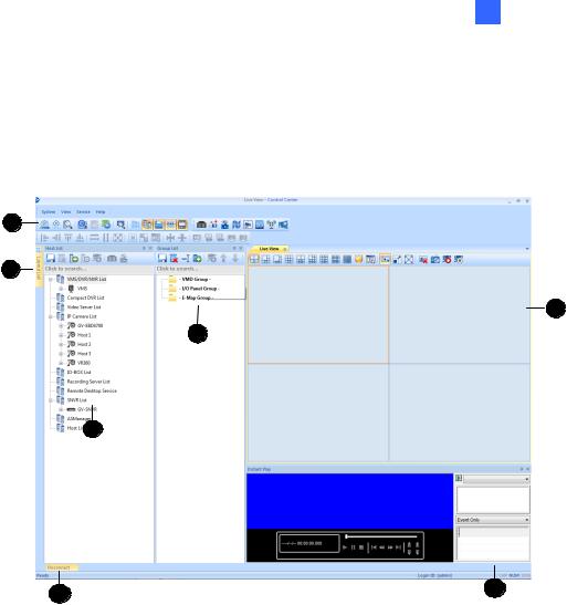
1.3.1The Control Center Main Window
1
5
4
3
2
|
7 |
|
6 |
|
|
|
|
|
|
|
|
|
|
Figure 1-1 |
|
|
|
|
|
No. |
Name |
|
|
Description |
1 |
Toolbar |
|
See 1.3.2 The Toolbar later. |
|
|
|
|
|
|
2 |
Host List |
|
Displays hosts and its channels in a tree diagram. See 1.3.3 The Host |
|
|
List. |
|||
|
|
|
|
|
|
|
|
|
|
3 |
Group List |
|
Displays hosts in Groups of VMD, I/O and E-Map. See 1.3.4 The Group |
|
|
List. |
|||
|
|
|
|
|
|
|
|
|
|
4 |
Live View |
|
Displays images from the hosts. Drag and drop the cameras from the |
|
|
Host List for live view display. See 3.1.2 Displaying Multi Views. |
|||
|
|
|
|
|
|
|
|
|
|
5 |
Layout List |
|
Click the tab to switch to the Layout List. The Layout List contains layouts |
|
|
for Video Wall. See 8.3.2 The Layout List. |
|||
|
|
|
|
|
|
|
|
|
|
6 |
Instant Play |
|
Displays the Instant Play window on the main window for playback. See |
|
|
5.1 Instant Playback. |
|||
|
|
|
|
|
|
|
|
|
|
7 |
Disconnect |
|
Click View on the main window and select Disconnected List to display |
|
|
the disconnected cameras from live view, Matrix View and Video Wall. |
|||
|
|
|
|
|
|
|
|
|
|
5
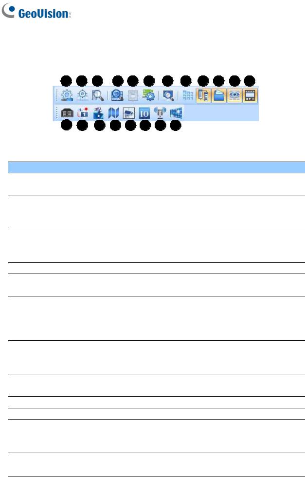
1.3.2The Toolbar
1 |
2 |
3 |
4 |
5 |
6 |
7 |
8 |
9 |
10 |
11 |
12 |
|
13 |
14 |
15 |
16 |
17 |
18 |
19 |
20 |
|
|
|
|
|
|
|
Figure 1-2 |
|||
No. Name |
Description |
|
|
|
|
||||
1. |
Configure |
Displays system settings including general settings, network settings, |
|||||||
VMD settings, Remote Desktop and Video Wall. |
|||||||||
|
|
||||||||
|
Application |
Configures position and resolutions of application windows, including |
|||||||
2. |
GV-DVR / NVR / VMS, Remote ViewLog, Remote E-Map, I/O Central |
||||||||
Position |
|||||||||
|
Panel, and up to 8 matrices. See 8.1 Application Position. |
||||||||
|
|
||||||||
|
|
Opens the Search Host window, with which you can detect and add |
|||||||
3. |
Search Host |
devices of the same LAN to the Host List and select a network card if |
|||||||
|
|
you have installed more than one. |
|||||||
4. |
Search Server |
Searches for Video Wall servers. See 8.3 Video Wall. |
|||||||
5. |
Open Activated |
Opens the activated layout on the Control Center’s main window. See |
|||||||
Layout |
8.3 Video Wall. |
|
|
|
|||||
|
|
|
|
||||||
|
|
Manages mass number of GV-IP Devices with integrated interface. |
|||||||
6. |
Batch Update |
You can change/assign IP address, rename devices, assign NAS and |
|||||||
Wizard |
view storage space information of multiple GV-IP Devices. See 9.4 |
||||||||
|
|||||||||
|
|
Batch Functions. |
|
|
|
||||
|
|
Searches for any remote servers with Remote Desktop service |
|||||||
7. |
Search Server |
activated. See Displaying a Remote Monitor on Video Wall, 8.3.7 |
|||||||
|
|
Displaying Remote Monitor, Web Page and Playing Back Videos. |
|||||||
8. |
Layout List |
Displays the Video Wall Layout List on the main window. See 8.3.2 |
|||||||
The Layout List. |
|
|
|
||||||
|
|
|
|
|
|||||
9. |
Host List |
Displays Host List on the main window. |
|||||||
10. |
Group List |
Displays the Group List on the main window. |
|||||||
Live View
Displays live views collectively on the main window. Drag and drop
11. cameras for live view display. For more detail, see 3.1.2 Displaying Window
Multi-Views.
12. Instant Play
Displays the Instant Play window on the main window. See 5.1 Instant
Playback.
6

1 Introduction
No. |
Name |
|
Description |
13. |
Remote DVR |
|
Allows the Control Center to access a remote client GV-DVR / NVR. |
|
See 6.1 Remote DVR. |
||
|
|
|
|
|
|
|
|
14. |
Remote DVR |
|
Allows the Control Center to access the desktop of a host GV-DVR / |
Desktop |
|
NVR and the operating system. See 6.2 Remote Desktop. |
|
|
|
||
|
|
|
|
15. |
Remote ViewLog |
|
Allows the Control Center to access the event files of different hosts |
|
and play them back. See 5.2 Remote ViewLog. |
||
|
|
|
|
16. |
Remote E-Map |
|
Allows you to monitor client DVR and GV-IP Devices on E-Maps. See |
|
9.1 Remote E-Map. |
||
|
|
|
|
|
|
|
|
17. |
VMD System |
|
Displays pop-up live views when a motion, input or temperature alert |
|
is detected. See 3.4 VMD Monitoring. |
||
|
|
|
|
|
|
|
|
18. |
I/O Central Panel |
|
Collectively manages I/O devices of different hosts. See I/O Central |
|
Panel, Chapter 7. |
||
|
|
|
|
19. |
Broadcast Service |
|
Speaks to multiple hosts over LAN or the Internet simultaneously. See |
|
4.2 Audio Broadcast. |
||
|
|
|
|
20. |
Matrix Quick |
|
Displays a selected camera view on the primary monitor when |
Zoom |
|
multiple monitors are used. For Matrix View, see 8.2 Matrix View. |
|
|
|
||
|
|
|
|
7

1.3.3The Host List
1 2 3 4 5 6 7
Figure 1-3
The controls on the Host List:
No. |
Name |
|
Description |
1 |
Save |
|
Saves the changes made in Host List. |
2 |
Delete |
|
Deletes the selected host. |
3 |
Add Host |
|
Adds a Host. |
|
|
|
|
4 |
Host Settings |
|
Displays the host settings of the selected host. |
5 |
Camera |
|
Click to watch live view, access Remote ViewLog and play back |
Information |
|
recordings instantly. |
|
|
|
||
6 |
Remote |
|
Access applications including Remote DVR, Remote Desktop and Event |
Control |
|
Data Query. See Remote DVR Applications, Chapter 6. |
|
|
|
||
7 |
Remote |
|
Plays back recordings of the selected camera. See 5.2 Remote ViewLog. |
ViewLog |
|
||
|
|
|
8

1 Introduction
1.3.4The Group List
1 |
2 |
3 |
4 |
5 |
6 |
7 |
8 |
9 |
Figure 1-4
The buttons on the Group List:
No. |
Name |
Description |
1 |
Save |
Saves the changes made in Group List. |
|
|
|
2 |
Delete |
Deletes the selected group. |
|
|
|
3 |
Rename Group |
Renames the selected group. |
|
|
|
4 |
Add Group |
Adds a new group under the selected category. |
|
|
|
5 |
Camera Information Looks up device information and access its live view. |
|
|
|
|
6 |
Move up |
Moves the selected camera up in its group. |
|
|
|
7 |
Move down |
Moves the selected camera down in its group. |
|
|
|
8 |
Matrix |
Displays matrix view. See 8.2 Matrix View. |
|
|
|
9 |
Remote ViewLog |
Plays back recordings of the selected camera. See 5.2 Remote |
|
|
ViewLog. |
|
|
|
9
Chapter 2 Getting Started
2.1 Installation
Follow the steps below to install GV-Control Center from the Software DVD or GeoVision Website.
IMPORTANT: By default, the GV-Control Center contains an Administrator account with the Login ID admin and no password. To change the password or create another account, see
10.7 Account Management.
Installing from Software DVD
1.Plug in the GV-USB Dongle to the computer.
2.Insert the Software DVD to your computer. It runs automatically and a window appears.
3.To install the USB device driver, select Install or Remove GeoVision GV-Series Driver and follow the on-screen instructions.
4.To install GV-Control Center, select Install GeoVision GV-Control Center and click Yes to accept the License Agreement.
5.Click GeoVision Control Center and follow the on-screen instructions.
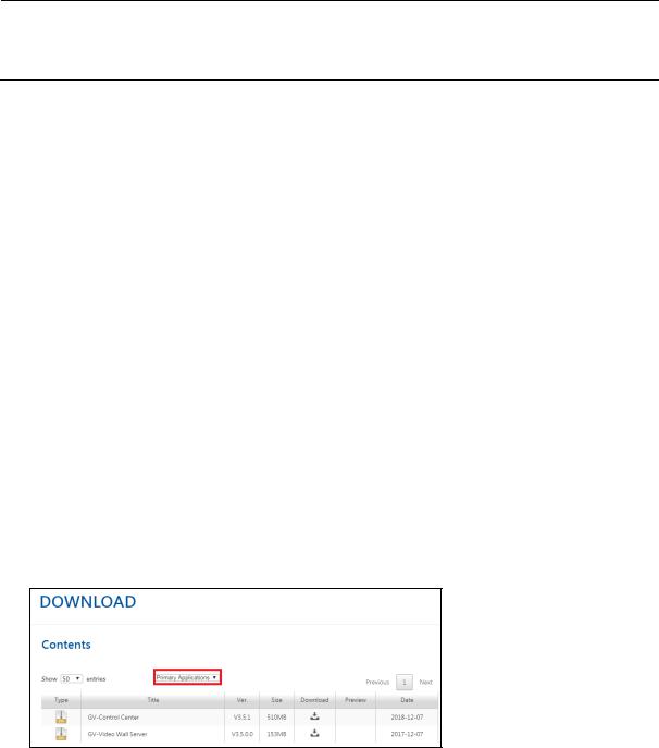
Downloading from GeoVision Website
1.Plug in the GV-USB Dongle to the computer.
2.Go to the Download page of GeoVision Website
3.To install the USB device driver, select Driver, F/W, Patch from the drop-down list to download the driver.
4.To install GV-Control Center, select Primary Applications from the drop-down list to download the software.
10

2 Getting Started
2.2 Hosts and Groups
You need to create hosts and groups before starting the services. To create hosts, you can use the Search Host function  (No. 3, Figure 1-2) to detect GV devices and compatible third-party IP devices on the same LAN and add them to the Host List, or you can follow the steps in the following section.
Note:
1.To use the Search Host function to locate GV devices, it is required to open TCP port 5201 on the client DVR, TCP port 5202 on the Video Server and Compact DVR, and UDP port 5200 on the Control Center.
2.If antivirus software is installed, the Search Host function may be interfered and will not detect the available hosts. In this case, turn off the antivirus software and try again.
11
2.2.1Creating a Host
You can create a host of the DVR, Compact DVR, Video Server, IP Camera, I/O Box and Recording Server. The Host Settings dialog box may look different among these devices. The following steps are an example of adding an IP camera host.
1.On the Host List window, click the Add Host button  (No. 3, Figure 1-3) and select Add IP Camera. This dialog box appears.
Figure 2-1
2.Type the host name, IP address, login ID and password of the host. Keep the communication port as default, unless otherwise necessary.
3.Click the Update Information button to request the number of cameras, I/O modules and streams of the host. When the update is complete, the message Update system information successfully appears.
4.Optionally select Stream 1 or Stream 2 for live view display. By default, the Stream setting is Auto and the received streaming is based on the streaming setting of the connected IP camera.
5.Click OK to add the host.
12

2 Getting Started
Tip:
1.To access the Web interface of the IP device, click Configure on the Host Settings dialog box (Figure 2-1).
2.To access live view of a camera, right-click the camera on the Host List and select Live View.
Note:
1.To add a DVR host, it is required to enable Control Center Service at the DVR; otherwise the message Unable to Connect will appear when accessing the live view. See 2.3 Connecting to Control Center.
2.The Control Center supports IP video devices using RTSP, ONVIF and PSIA standards. To connect the IP device compatible with any of these standards, select Protocol from the Brand drop-down list. See RTSP Streaming, Appendix C.
2.2.2Creating a Group
You can group cameras from different hosts by location and purpose (such as matrix view display).
1.On the Group List window, click the Add Group button  (No. 4, Figure 1-4).
2.Name the created group.
3.Drag the desired cameras from the Host List to the created group.
4.Click the Save button  (No. 1, Figure 1-4) to store your settings.
Tip: Right-click a camera to see the device information and access the live view.
13
2.3 Connecting to Control Center
The Control Center supports several types of hosts. Only the DVR (GV-DVR / NVR / VMS) hosts need to be configured and started for connection to Control Center.
To configure the client DVR in order to access the Control Center services remotely through a network connection, click the Network button on the main screen, select Control Center Server, and select Start Default Service or Start All Service to connect.
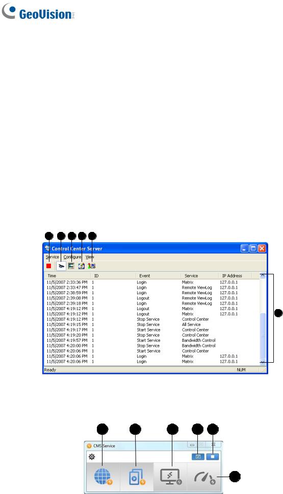
2.3.1The Control Center Server Window
When the client DVR starts the Control Center Service (CCS) as described above, the server will be minimized to the system tray. Click the server’s icon to restore its window.
GV-DVR / NVR
1 |
3 |
4 |
5 |
6 |
7
Figure 2-2
GV-VMS
3 |
4 |
5 |
2 |
1 |
6
Figure 2-3
14

2 Getting Started
The controls on the CMS Server:
No. |
Name |
Description |
1 |
Stop All Service |
Stops all Control Center Server services. |
|
|
|
2 |
Start Default Service |
Starts all default services. |
3
Start / Stop
Control Center Service
Starts or stops these services: Matrix, I/O Central Panel and Remote DVR. It indicates that the host allows or not allows the Control Center to access the I/O modules and GV-DVR / NVR / VMS.
4 |
Start/Stop Remote |
Allows or prohibits the Control Center to access the ViewLog |
|
ViewLog Service |
files. |
||
|
|||
5 |
Start/Stop Desktop |
Allows or prohibits the Control Center to control the desktop. |
|
Service |
|||
|
|
||
|
Start / Stop |
Allows or prohibits the Bandwidth Control Server to control the |
|
6 |
Bandwidth Control |
bandwidth. See 11.11 Bandwidth Control Applications, |
|
|
Service |
GV-DVR User’s Manual on the Software DVD. |
|
7 |
Event List |
Indicates login ID, event type, event time, service activation |
|
and IP address. |
|||
|
|
Note:
1.By default, the live stream images of GV-DVR / NVR / VMS are compressed for better bandwidth control at the cost of increased CPU usage. The number of remote connections allowed from the same GV-DVR / NVR / VMS depends on the specs and the usage of the DVR’s / NVR’s / VMS’ CPU.
2.For GV-VMS V17.1 or later, optionally enable the Substream FIFO function under the Settings  of CMS Server (Figure 2-3) for reduced CPU usage of the GV-VMS and improved streaming quality at the cost of increased bandwidth. The number of remote connections allowed from the same GV-VMS depends on the amount of bandwidth available.
3.To access certain specified streams of a GV-VMS host from multiple CMS servers under the same LAN, the Multicast function is recommended. For details, see 9.6 Multicast Setting.
15
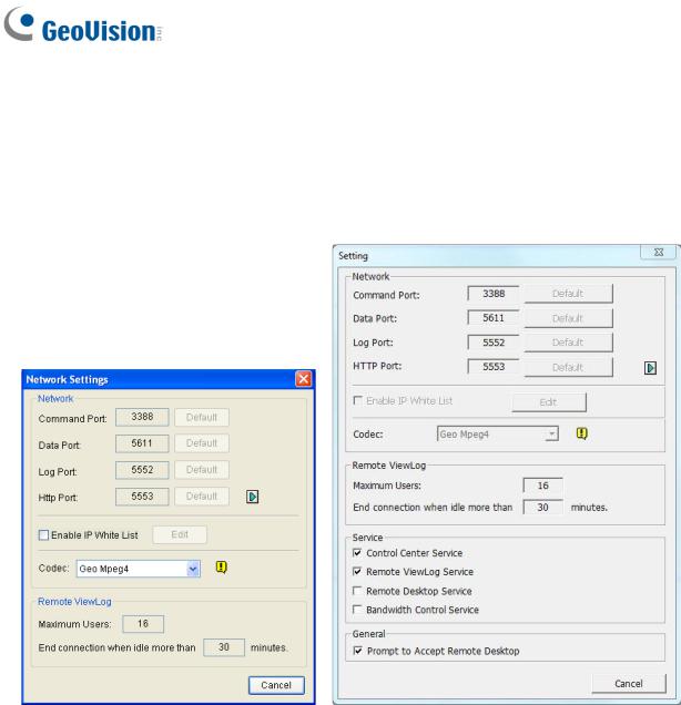
2.3.2Advanced Settings
To configure the CCS Server, click Configure on the window menu.
[Network Settings] Keep the four communication ports as default, unless otherwise necessary.
Figure 2-4 GV-DVR / NVR |
Figure 2-5 GV-VMS |
Enable IP White List: Limits access to the Control Center Server by assigning IP ranges.
Codec: Sets video compression to Geo Mpeg4 or Geo H264. Note Remote Desktop does not support Geo H264 codec.
UPnP: To automatically configure three communication ports on your router, click the Arrow button beside Http Port for UPnP settings.
Remote ViewLog : Sets the maximum number of users to access the video files for playback from 1 to 16. It also sets the idle time after which to end the Remote ViewLog application.
16
2 Getting Started
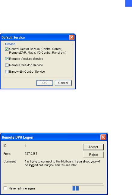
[Event Log Settings] Sets the log storage path and duration.
[Set Default Service] Select the desired services to set as default.
Figure 2-6 GV-DVR / NVR
[Prompt to accept] The client can be prompted to accept or reject the connection when the Control Center attempts to access its GV-System (through Remote DVR service) or Desktop (through Remote Desktop).
Figure 2-7 GV-DVR / NVR
[Auto start default service when Windows starts] Automatically runs the default services at Windows startup.
[Hide when minimized] Hides the minimized Control Center Server window to the system tray.
17
Chapter 3 Live Video
3.1 Live View
You can choose to display live views in separate windows or collectively on the Live View window.
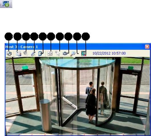
3.1.1Displaying Single Live View
To display single live view window (Figure 3-1):
On the Host List (Figure 1-3) or Group List (Figure 1-4), right-click any camera and select
Live View.
On the Host List or Group List, select a camera, click the Camera Information button
and select Live View.
On a Remote E-Map window (Figure 9-11), click a camera icon.
1 2 3 4 5 6 7 8 9 10
Figure 3-1
18

3 Live Video
The controls on the single Live View window:
No. |
Name |
Description |
|
|
|
Change
1 Switches to another camera of the same host. Camera
Stream1/Stream2: Changes the size of the live video. The size corresponds to the video resolution set at the host. The size choices are only available when the video resolution is higher than 320 x 240.
Defog: Enhances image visibility.
Stabilizer: Stabilizes live images.
PIP View: Refers to Picture in Picture. You can zoom in on the video. See 3.2 PIP and PAP View.
2 |
Change Size |
PAP View: Refers to Picture and Picture. You can create a split video |
|
|
|
effect with multiple close-up views on the video. See 3.2 PIP and PAP |
|
|
|
View. |
|
|
|
Fisheye: Dewarps the fisheye view to quad view. |
|
|
|
IMV1 Panomorph: Dewarps the fisheye view. Note this option is only |
|
|
|
available for a third-party fisheye camera and when the camera |
|
|
|
resolution is set as 1280 x 1024 or higher. |
|
|
|
Wide Angle Lens Dewarping: Corrects live view distortions. See |
|
|
|
3.1.4 Adjusting Distorted Views. |
|
|
|
|
|
3 |
Audio |
Receives audio from the host. |
|
|
|
|
|
4 |
Microphone |
Enables speaking to the host. A microphone must be installed properly in |
|
the computer. |
|||
|
|
Enables and configures the audio and video settings; Adjusts the image |
|
5 |
Setting |
color (Normalization) and decreases the fogginess of the image (Sampling |
|
|
|
Range). Fixes the window to a specific size. |
|
|
|
|
|
6 |
PTZ |
Activates the PTZ control by selecting PTZ Panel or PTZ Automation. |
|
|
|
|
|
|
Visual |
Allows you to change the current state of an electronic device, e.g. light |
|
7 |
ON, by clicking on its image directly. The function is only available when |
||
Automation |
|||
|
the same function is set at the host. |
||
|
|
||
8 |
Snapshot |
Takes the snapshot of the displayed live video. |
|
|
|
|
|
9 |
Zoom |
Enlarges the video by selecting 1.0x, 2.0x and 3.0x. |
|
|
|
|
|
10 |
Instant Play |
Plays back the recording in the last 10 seconds, 30 seconds, 1 minute or 5 |
|
minutes. |
|||
|
|
|
19

Note: When the video resolution of the IP camera is larger than the screen resolution of the Control Center, the maximum live video you can view is approximately half size of that IP Camera resolution.
3.1.2Displaying Multi Views
The Live View window is designed for multi-channel live view display. You can monitor up to 36 channels simultaneously. To display live view on this window, you can:
Drag the cameras from the Host List (Figure 1-3) to Live View window (Figure 3-2).
From a Remote E-Map (Figure 9-11), click on a camera icon.
Note: For live views enabled from Remote E-Map to display on the Live View window, define the display position in Application Position window. For detail, see Step 3 in 8.1 Application Position.
1 |
2 |
3 |
4 |
5 |
6 |
7 |
8 |
9 |
10 |
11
12
Figure 3-2
20

3 Live Video
The controls on the Live View window:
No. |
Name |
|
Description |
|
|
|
|
1. |
Screen Division |
|
Select a screen division. |
|
|
|
|
|
|
|
Click Set Quad to specify the number of rows and columns in the |
2. |
Favorite |
|
live view layout. Click Add to List to save the current layout and |
|
|
|
camera assignment to the Favorite list. |
|
|
|
|
|
|
|
Contains the following settings: |
|
|
|
• Full-screen: You can designate a monitor to be used when |
|
|
|
you click the full-screen button. |
|
|
|
• QView: When there are two or more monitors connected, you |
|
|
|
can designate a monitor for QView function if you wish to view |
3. |
Live View Setup |
|
a single-channel live view as full screen on a separate monitor. |
|
|
|
• Caption: Select to display the camera name and host name. |
|
|
|
• Waveout When Zoomed: Enable audio waveout when a live |
|
|
|
view is selected and extended to single view. |
|
|
|
• Snapshot Select: Set the storage path for captured |
|
|
|
snapshots. |
|
|
|
|
4. |
Fit Window |
|
Extends the live view to fill the channel. |
|
|
|
|
5. |
Keep Image Ratio |
|
Displays the live view proportionally to its source. |
|
|
|
|
6. |
Full Screen |
|
Changes the live view window to full-monitor display. |
|
|
|
|
7. |
Close all video |
|
Closes all the live view channels. |
|
|
|
|
8. |
Snapshot |
|
Snapshots and saves the live views currently displayed on the |
|
Live View window. |
||
|
|
|
|
|
|
|
|
9. |
Monitor |
|
Enables monitoring of all the live views. |
|
|
|
|
10. |
Stop All Monitoring |
|
Disenables monitoring of all the live views. |
|
|
|
|
|
|
|
The monitoring status is indicated by the color of the device |
|
|
|
name. |
|
|
|
For GV-DVR / NVR / VMS / GV-IP Device / GV-Recording Server |
|
|
|
hosts (V1.25 or later): |
|
|
|
• Red: |
11 |
Monitoring Status |
|
A channel from GV-DVR / NVR / VMS V17.1 or later is |
|
|
|
being monitored and recorded. |
|
|
|
A GV-IP Device / GV-Recording Server host is being |
recorded.
• Green: The channel is being monitored but not recorded.
• Yellow: The camera is not monitored nor recorded.
21
Loading...