


GV-IP Camera
Quick Start Guide
 Box Camera
 Ultra Box Camera
 Arctic Box Camera
 Target Box Camera
Before attempting to connect or operate this product, |
ICH265-BX-BXE-A |
please read these instructions carefully and save this manual for future use. |

© 2019 GeoVision, Inc. All rights reserved.
Under the copyright laws, this manual may not be copied, in whole or in part, without the written consent of GeoVision.
Every effort has been made to ensure that the information in this manual is accurate. GeoVision, Inc. makes no expressed or implied warranty of any kind and assumes no responsibility for errors or omissions. No liability is assumed for incidental or consequential damages arising from the use of the information or products contained herein. Features and specifications are subject to change without notice. Note: no memory card slot or local storage function for Argentina.
GeoVision, Inc.
9F, No. 246, Sec. 1, Neihu Rd., Neihu District, Taipei, Taiwan Tel: +886-2-8797-8377
Fax: +886-2-8797-8335 http://www.geovision.com.tw
Trademarks used in this manual: GeoVision, the GeoVision logo and GV series products are trademarks of GeoVision, Inc.
July 2019
|
Contents |
|
Contents .............................................................................. |
i |
|
Caution |
.............................................................................. |
iv |
Safety Notice .................................................................... |
iv |
|
Options .............................................................................. |
v |
|
Creating GV-IP Camera’s Login Credentials................ |
vii |
|
Note for Installing Camera Outdoor............................. |
viii |
|
Note for USB Storage and WiFi Adapter ........................ |
ix |
|
Note for Silica Gel Bags ................................................... |
ix |
|
Chapter 1 Box Camera ..................................................... |
1 |
|
1.1 |
Packing List .............................................................................. |
3 |
|
1.1.1 For H.265 Cameras ..................................................... |
3 |
|
1.1.2 For H.264 Cameras ..................................................... |
4 |
1.2 |
Overview .................................................................................. |
5 |
1.3 |
Connecting the Camera............................................................ |
8 |
1.4 |
Accessory Installation............................................................. |
10 |
|
1.4.1 C-Mount Lenses......................................................... |
10 |
|
1.4.2 Infrared Illuminators (Optional)................................... |
11 |
1.5 |
I/O Terminal Block .................................................................. |
12 |
|
1.5.1 Pin Assignment.......................................................... |
12 |
|
1.5.2 Connecting to GV-Relay V2 (Optional)....................... |
13 |
i |
|
|
1.6 |
Loading Factory Default.......................................................... |
14 |
|
|
1.6.1 |
Using the Web Interface............................................. |
14 |
|
1.6.2 |
Directly on the Camera .............................................. |
15 |
Chapter 2 IR Arctic Box Camera ................................... |
16 |
||
2.1 |
Packing List ............................................................................ |
17 |
|
2.2 |
Overview ................................................................................ |
18 |
|
|
2.2.1 GV-BX4700-E ............................................................. |
18 |
|
2.3 |
Installation .............................................................................. |
19 |
|
2.4 |
Connecting the Camera.......................................................... |
23 |
|
2.5 |
Notice for Using the IR Arctic Box Camera ............................. |
25 |
|
|
2.5.1 |
Enabling IR LED after Loading Default....................... |
26 |
|
2.5.2 |
Disabling Status LED under Low Light Conditions...... |
27 |
2.6 |
Loading Factory Default.......................................................... |
28 |
|
Chapter 3 Target Box Camera ....................................... |
29 |
||
3.1 |
Packing List ............................................................................ |
29 |
|
3.2 |
Overview ................................................................................ |
30 |
|
3.3 |
Installation .............................................................................. |
31 |
|
3.4 |
Connecting the Camera.......................................................... |
33 |
|
3.5 |
Loading Factory Default.......................................................... |
34 |
|
|
3.5.1 Using the Web Interface.............................................. |
34 |
|
|
3.5.2 Directly on the Camera ............................................... |
34 |
|
Chapter 4 Accessing the Camera.................................. |
35 |
||
ii
4.1 |
System Requirement .............................................................. |
35 |
||
4.2 |
Accessing the Live View ......................................................... |
35 |
||
|
4.2.1 Checking the Dynamic IP Address ............................. |
36 |
||
|
4.2.2 |
Configuring the IP Address ........................................ |
37 |
|
|
4.2.3 |
Configuring the Wireless Connection ......................... |
39 |
|
4.3 |
Adjusting Image Clarity........................................................... |
42 |
||
Chapter 5 |
The Web Interface ......................................... |
44 |
||
Chapter 6 |
Upgrading System Firmware ....................... |
47 |
||
iii
Caution
Risk of explosion if battery is replaced by an incorrect type. Dispose of used batteries according to the instructions.
Safety Notice
The GV-IPCAM uses a Lithium battery as the power supply for its internal real-time clock (RTC). The battery should not be replaced unless required!
If the battery does need replacing, please observe the following:
Danger of Explosion if battery is incorrectly replaced
Replace only with the same or equivalent battery, as recommended by the manufacturer
Dispose of used batteries according to the manufacturer's instructions
iv

Options
Optional devices can expand your camera’s capabilities and versatility. Contact your dealer for more information.
Device
Power Adapter
GV-PA191 PoE
Adapter
GV-PA482 PoE
Adapter
GV-POE Switch
GV-Mount
Accessories
Description
The power adapter is available for all Box Camera, Ultra Box Camera, and Target Box Camera. Contact your sales representative for the countries and areas supported.
The GV-PA191 PoE adapter is designed to provide power and network connection to the cameras over a single Ethernet cable.
The GV-PA482 PoE adapter is designed to provide power and network connection to GV-BX4700-E over a single Ethernet cable.
The GV-POE Switch is designed to provide power along with network connection for IP devices. The GV-POE Switch is available in various models with different numbers and types of ports.
The GV-Mount Accessories provide a comprehensive lineup of accessories for installation on ceiling, wall corner and pole. For details, see GVMount Accessories Installation Guide.
v

Device
GV-WiFi Adapter
GV-Relay V2
Description
The GV-WiFi Adapter is a plug-and-play device designed to connect your camera to to wireless network. The product complies with IEEE 802.11 b/g/n (Draft 3.0) standards for wireless networking.
Note: Only the compatible models and firmware versions can support GV-WiFi Adapter.
The GV-Relay V2 is designed to expand the voltage load of GV IP devices. It provides 4 relay outputs, and each can be set as normally open (NO) or normally closed (NC) independently as per your requirement.
vi
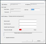
Creating GV-IP Camera’s Login
Credentials
The default Administrator and Guest accounts are no longer supported by
GV-IPCAM H.265 series firmware V1.14 or later. When purchasing a new camera or performing factory resetting, you need to set up a login username and password for the camera.
1.Download and install GV-IP Device Utility from the company website.
2.On the GV-IP Device Utility window, click  to search for your GVIP camera.
3.Double-click your GV-IP camera in the GV-IP Device Utility list. This dialog box appears.
4.Click the Change Username and Password tab to type a new username and password. Note that the new password must meet the password strength requirements.
5.Optionally click Upgrade all devices to use the same username and password on all other devices.
vii
Note for Installing Camera Outdoor
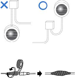
When installing the IR Arctic Box Camera outdoor, be sure that:
1.The camera is set up above the junction box to prevent water from entering the camera along the cables.
2.Any PoE, power, audio and I/O cables are waterproofed using waterproof silicon rubber or the like.
3.The silica gel bag loses its effectiveness when the dry camera is opened. To prevent the lens from fogging up, replace the silica gel bag every time you open the camera, and conceal the gel bag in camera within 2 minutes of exposing to open air.
viii
Note for USB Storage and WiFi Adapter
Mind the following limitations and requirements for using USB storage and GV-WiFi Adapter:
1.The USB hard drive must be of 2.5’’ or 3.5’’, version 2.0 or above.
2.The USB hard drive’s storage capacity must not exceed 2TB.
3.USB flash drives and USB hubs are not supported.
4.External power supply is required for the USB hard drive.
5.To connect a GV-WiFi Adapter, make sure it is connected before the camera is powered on.
Note for Silica Gel Bags
1.The silica gel bag loses its effectiveness when the dry camera is opened. To prevent the lens from fogging up, replace the silica gel bag every time you open the camera, and conceal the gel bag in camera within 2 minutes of exposing to open air.
2.When the camera is shipped, a silica gel bag will be included inside the camera. For the first-time user, replace the silica gel bag prior to the installation to avoid foggy live view.
ix

1 Box Camera
Chapter 1 Box Camera
The Box Camera is a series of indoor IP cameras consisting of fixed focal and varifocal models in different resolutions. The Box Camera supports lens replacement and features an automatic infrared-cut filter for day and night surveillance. The super low lux models are capable of displaying color live view in near darkness. Models equipped with a mini USB port can be connected wirelessly through a GV-WiFi Adapter (optional). The WDR Pro models can produce clear image for scenes with contrasting intensity of lights. Models using P-Iris allow for precise control of exposure, producing images with better clarity and contrast. The FD (Face Detection) models can detect human faces in the live view mode.
The Box Camera models are detailed below:
|
Model No. |
|
|
Specifications |
Description |
|
|
|
|
|
|
|
|
|
|
|
|
|
|
2 MP, H.265, |
|
GV-BX2700-8F |
|
|
|
|
Super Low |
|
|
|
|
|
Lux, D/N, |
|
|
|
|
|
|
Fixed Iris, f: 2.8 mm, |
|
|
|
|
|
|
WDR Pro |
|
|
|
|
|
|
F/1.8, 1/2.5’’ CS |
|
|
|
|
|
|
4 MP, H.265, |
|
|
|
|
|
|
Lens |
|
|
|
|
Fixed Lens |
|
Super Low |
|
GV-BX4700-8F |
|
|
|
|||
|
|
|
|
Lux, D/N, |
||
|
|
|
|
|
|
|
|
|
|
|
|
|
WDR Pro |
|
|
|
|
|
Fixed Iris, f: 2.95 |
5 MP, H.265, |
GV-BX5700-8F |
|
|
|
mm, F/2.0, 1/1.8’’ CS |
Low Lux, D/N, |
|
|
|
|
|
|
Lens |
WDR |
|
|
|
Varifocal |
|
DC drive Iris, f: 4.1 ~ |
12 MP, H.264, |
GV-BX12201 |
|
|
9 mm, F/1.6, 1/1.8” |
|||
|
Lens |
|
D/N |
|||
|
|
|
|
CS Lens |
||
|
|
|
|
|
|
|
1
P-Iris Models
Model No. |
|
|
Specifications |
|
GV-BX2700-3V |
|
|
|
P-Iris, f: 3 ~ 10.5 |
|
|
|
|
|
|
|
|
|
mm, F/1.4, 1/2.7” |
|
|
|
|
|
GV-BX4700-3V |
|
Varifocal |
|
CS Lens |
|
|
|
||
|
|
|
|
|
|
|
Lens |
|
|
|
|
|
|
|
GV-BX5700-3V |
|
|
|
P-Iris, f: 3.6 ~ 10 |
|
|
|
|
|
|
|
|
|
mm, F/1.5, 1/1.8” |
GV-BX8700 |
|
|
|
CS Lens |
|
|
|
|
|
Description
2 MP, H.265, Super
Low Lux, D/N,
WDR Pro
4 MP, H.265, Super
Low Lux, D/N,
WDR Pro
5 MP, H.265, Low
Lux, D/N, WDR
8 MP, H.265, Super
Low Lux, D/N,
WDR Pro
FD (Face Detection) Models
Model No. |
Specifications |
GV-BX2600-FD
P-Iris, f: 3 ~ 10.5
mm, F/1.4, 1/2.7” GV-BX2700-FD Varifocal CS Lens
Lens
GV-BX4700-FD
P-Iris, f: 3.6 ~ 10 GV-BX8700-FD mm, F/1.5, 1/1.8”
CS Lens
Description
2 MP, H.265,
Super Low Lux,
D/N, WDR Pro
4 MP, H.265,
Super Low Lux,
D/N, WDR Pro
8 MP, H.265, Low
Lux, D/N, WDR Pro
2

1 Box Camera
1.1 Packing List
1.1.1 For H.265 Cameras
Box Camera
Terminal Block (2-Pin and 3-Pin)
Fixed Focal or Varifocal Megapixel Lens
Six Lens Rings (only for Varifocal Lens)
Video Out Wire
Camera Holder
Holder Screw x 2
Download Guide
Warranty Card
3
1.1.2 For H.264 Cameras
Box Camera
Terminal Block (2-Pin and 3-Pin)
Fixed Focal or Varifocal Megapixel Lens
Six Lens Rings (only for Varifocal Lens)
Video Out Wire
Camera Holder
Holder Screw x 2
Power Adapter
Download Guide
Warranty Card
Note: The power adapter can be excluded upon request.
4
1 Box Camera
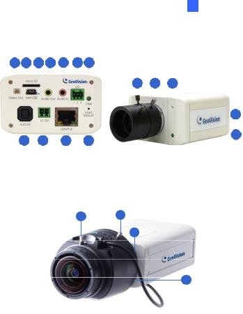
1.2 Overview
1 |
2 |
3 |
|
4 |
5 |
|
6 |
7 |
|
|
|
|
|
|
|
|
|
|||||||
|
|
|
|
|
|
|
|
|
|
|
|
|
|
|
12 |
13 |
14 |
|
15 |
|||||
|
|
|
|
|
|
|
|
|
|
|
|
|
|
|
||||||||||
|
|
|
|
|
|
|
|
|
|
|
|
|
|
|
|
|
|
|
|
|
|
|
||
|
|
|
|
|
|
|
|
|
|
|
|
|
|
|
|
|
|
|
|
|
|
|
||
|
|
|
|
|
|
|
|
|
|
|
|
|
|
|
|
|
|
|
|
|
|
|
||
|
|
|
|
|
|
|
|
|
|
|
|
|
|
|
|
|
|
|
|
|
|
|
||
|
|
|
|
|
|
|
|
|
|
|
|
|
|
|
|
|
|
|
|
|
|
|
||
|
|
|
|
|
|
|
|
|
|
|
|
|
|
|
|
|
|
|
|
|
|
|
|
16 |
|
|
|
|
|
|
|
|
|
|
|
|
|
|
|
|
|
|
|
|
|
|
|
|
|
|
|
|
|
|
|
|
|
|
|
|
|
|
|
|
|
|
|
|
|
|
|
|
|
|
|
|
|
|
|
|
|
|
|
|
|
|
|
|
|
|
|
|
|
|
|
|
|||
|
|
8 |
9 |
|
|
10 |
|
|
11 |
|
|
|
|
|
|
|
|
|||||||
|
|
|
|
|
|
|
|
|
|
|
|
|
|
|
||||||||||
|
|
|
Figure 1-1a |
|
|
|
|
|
Figure 1-1b: |
|
|
|
||||||||||||
|
|
|
|
|
|
|
|
|
|
|
|
|
|
|
GV-BX2700 Series / 4700 |
Series / 5700 |
||||||||
|
|
|
|
|
|
|
|
|
|
|
|
|
|
|
Series / 8700 / 2600-FD / 2700-FD / |
|||||||||
|
|
|
|
|
|
|
|
|
|
|
|
|
|
|
|
4700-FD / 8700-FD |
||||||||
Figure 1-1c
GV-BX12201
5

Note:
1.The Auto Iris Connector (No. 8) is only functional for the models with auto iris lens.
2.The Zoom Screw (No. 13) doesn’t work on the models with fixed lens.
3.The Memory Card Slot (No. 2) is currently not supported for GVBX12201.
4.Mini USB Slot (No. 3) connected to USB hard drive is currently not supported for GV-BX12201.
No. |
|
|
Name |
|
Description |
|
|
|
|
|
Connects to a portable monitor for setting the |
1 |
|
|
Video Out |
|
focus and angle of Box Camera during initial |
|
|
|
|
|
installation. |
2 |
|
|
Memory Card |
|
Inserts a micro SD card (SD/SDHC, version |
|
|
Slot |
|
2.0 only, Class 10) to store recording data. |
|
|
|
|
|
||
3 |
|
|
Mini USB Slot |
|
Connects to a GV-WiFi Adapter or a USB |
|
|
|
hard drive. |
||
|
|
|
|
|
|
4 |
|
|
Audio Out |
Connects a speaker for audio output. |
|
5 |
|
|
Audio In |
Connects a microphone for audio input. |
|
6 |
|
|
I/O Terminal |
|
Connects to I/O devices. For details, see 1.6 |
|
|
Block |
|
I/O Terminal Block. |
|
|
|
|
|
||
7 |
|
|
Power LED |
|
Indicates the power is supplied. For detail, |
|
|
|
see the table below. |
||
|
|
|
|
|
|
8 |
|
|
Auto Iris |
|
Plug the iris control cable to the connector. |
|
|
Connector |
|
||
|
|
|
|
|
|
9 |
|
|
DC 12V Port |
|
Connects to power. |
6

|
|
|
|
|
|
1 |
Box Camera |
|
|
|
|
|
|
|
|
||
No. |
|
|
Name |
|
Description |
|
||
10 |
|
|
LAN / PoE |
|
Connects to a 10/100 Ethernet or PoE. |
|
||
11 |
|
|
Default |
|
Restores the camera to factory default. For |
|
||
|
|
|
details, see 1.7 Loading Factory Default. |
|
||||
|
|
|
|
|
|
|||
12 |
|
|
Iris Screw |
|
Adjusts the iris of the camera. |
|
||
13 |
|
|
Zoom Screw |
|
Adjusts the zoom of the camera. |
|
||
14 |
|
|
Microphone |
Records the sounds. |
|
|||
15 |
|
|
Focus Screw |
Adjusts the focus of the camera. |
|
|||
16 |
|
|
Status LED |
|
Turns on when the unit is ready for use. For |
|
||
|
|
|
detail, see the table below. |
|
||||
|
|
|
|
|
|
|||
|
|
|
|
|
||||
LED |
|
|
|
Description |
|
|||
Power LED turns green |
The system powers on and succeeds to boot |
|
||||||
up. |
|
|||||||
|
|
|
|
|
||||
Status LED turns green |
The system is ready for use. |
|
||||||
Note: For GV-BX2600-FD, the Status LED (No. 16, Figure 1-1b) turns off after 10 seconds into startup and turns on again when the device is ready for operation,
7
 Loading...