


 Loading...
GV-IPCam
Quick Start Guide
 Cube Camera
 Mini Fixed Dome
 Mini Fixed Rugged Dome
 Target Mini Fixed Dome
 Target Mini Fixed Rugged Dome
Before attempting to connect or operate this product, |
ICH265HISI2V10-B |
please read these instructions carefully and save this manual for future use. |
Caution
Risk of explosion if battery is replaced by an incorrect type. Dispose of used batteries according to the instructions.
Safety Notice
The GV-IPCAM uses a Lithium battery as the power supply for its internal real-time clock (RTC). The battery should not be replaced unless required!
If the battery does need replacing, please observe the following:
Danger of Explosion if battery is incorrectly replaced
Replace only with the same or equivalent battery, as recommended by the manufacturer
Dispose of used batteries according to the manufacturer's instructions

© 2017 GeoVision, Inc. All rights reserved.
Under the copyright laws, this manual may not be copied, in whole or in part, without the written consent of GeoVision.
Every effort has been made to ensure that the information in this manual is accurate. GeoVision, Inc. makes no expressed or implied warranty of any kind and assumes no responsibility for errors or omissions. No liability is assumed for incidental or consequential damages arising from the use of the information or products contained herein. Features and specifications are subject to change without notice. Note: no memory card slot or local storage function for Argentina.
GeoVision, Inc.
9F, No. 246, Sec. 1, Neihu Rd., Neihu District, Taipei, Taiwan Tel: +886-2-8797-8377
Fax: +886-2-8797-8335 http://www.geovision.com.tw
Trademarks used in this manual: GeoVision, the GeoVision logo and GV series products are trademarks of GeoVision, Inc.
September 2017
Contents
Contents .............................................................................. |
|
i |
|
Options ............................................................................. |
|
iv |
|
Note for Installing Camera Outdoor.............................. |
vii |
||
Chapter 1 Mini Fixed Dome (Part I) & Mini Fixed |
|
||
Rugged Dome..................................................................... |
1 |
||
1.1 |
Packing List .............................................................................. |
4 |
|
1.2 |
Overview .................................................................................. |
6 |
|
|
1.2.1 GV-MFD120 / 130 / 320 ............................................... |
6 |
|
|
1.2.2 GV-MFD1501 Series / 2401 Series / 2501 Series / 3401 |
||
|
Series / 5301 Series .............................................................. |
8 |
|
|
1.2.3 GV-MDR .................................................................... |
10 |
|
1.3 |
Installation .............................................................................. |
13 |
|
|
1.3.1 GV-MFD Series.......................................................... |
13 |
|
|
1.3.2 GV-MDR Series ......................................................... |
15 |
|
1.4 |
Connecting the Camera.......................................................... |
20 |
|
|
1.4.1 |
Wire Definition ........................................................... |
20 |
|
1.4.2 Power and Network Connection................................. |
21 |
|
|
1.4.3 |
Vehicle Installation ..................................................... |
22 |
1.5 |
Loading Factory Default.......................................................... |
23 |
|
|
1.5.1 |
Using the Web Interface............................................. |
23 |
|
1.5.2 |
Directly on the Camera .............................................. |
24 |
Chapter 2 Mini Fixed Dome (Part II) .............................. |
25 |
||
2.1 |
Packing List ............................................................................ |
26 |
|
2.2 |
Overview ................................................................................ |
27 |
|
2.3 |
Installation .............................................................................. |
29 |
|
2.4 |
Connecting the Camera.......................................................... |
32 |
|
i

2.4.1 |
Wire Definition ........................................................... |
32 |
2.4.2 |
Voltage Load Expansion (Optional)............................ |
33 |
2.5 Loading Factory Default.......................................................... |
34 |
|
2.5.1 |
Using the Web Interface............................................. |
34 |
2.5.2 |
Directly on the Camera .............................................. |
34 |
Chapter 3 Target Mini Fixed Dome................................ |
35 |
||
3.1 |
Packing List ............................................................................ |
36 |
|
3.2 |
Overview ................................................................................ |
37 |
|
|
3.2.1 GV-EFD2700 ............................................................. |
39 |
|
3.3 |
Installation .............................................................................. |
41 |
|
3.4 |
Connecting the Camera.......................................................... |
44 |
|
|
3.4.1 |
I/O Connector ............................................................ |
45 |
|
3.4.2 |
Voltage Load Expansion (Optional)............................ |
46 |
3.5 |
Loading Factory Default.......................................................... |
47 |
|
|
3.5.1 |
Using the Web Interface............................................. |
47 |
|
3.5.2 |
Directly on the Camera .............................................. |
47 |
Chapter 4 Target Mini Fixed Rugged Dome |
.................48 |
||
4.1 |
Packing List ............................................................................ |
49 |
|
4.2 |
Overview ................................................................................ |
51 |
|
|
4.2.1 GV-EDR2700............................................................. |
52 |
|
4.3 |
Installation .............................................................................. |
53 |
|
4.4 |
Connecting the Camera.......................................................... |
60 |
|
4.5 |
Loading Factory Default.......................................................... |
61 |
|
|
4.5.1 |
Using the Web Interface............................................. |
61 |
|
4.5.2 |
Directly on the Camera .............................................. |
61 |
Chapter 5 Cube Camera ................................................. |
63 |
|
5.1 |
Packing List ............................................................................ |
64 |
5.2 |
Overview ................................................................................ |
65 |
5.3 |
Installation .............................................................................. |
66 |
5.4 |
Connecting the Camera.......................................................... |
68 |
ii
5.5 Loading Factory Default.......................................................... |
69 |
|
5.5.1 |
Using the Web Interface............................................. |
69 |
5.5.2 |
Directly on the Camera .............................................. |
69 |
Chapter 6 Advanced Cube Camera............................... |
70 |
||
6.1 |
Packing List ............................................................................ |
71 |
|
6.2 |
Overview ................................................................................ |
72 |
|
6.3 |
Installation .............................................................................. |
74 |
|
6.4 |
Connecting the Camera.......................................................... |
76 |
|
6.5 |
Loading Factory Default.......................................................... |
77 |
|
|
6.5.1 |
Using the Web Interface............................................. |
77 |
|
6.5.2 |
Directly on the Camera .............................................. |
77 |
Chapter 7 |
Accessing the Camera.................................. |
78 |
||
7.1 |
System Requirement .............................................................. |
78 |
||
7.2 |
Accessing the Live View ......................................................... |
79 |
||
|
7.2.1 Checking the Dynamic IP Address ............................. |
80 |
||
|
7.2.2 |
Configuring the IP Address ........................................ |
82 |
|
|
7.2.3 |
Configuring the Wireless Connection ......................... |
84 |
|
7.3 |
Adjusting Image Clarity........................................................... |
87 |
||
Chapter 8 |
The Web Interface ......................................... |
90 |
||
Chapter 9 |
Upgrading System Firmware ....................... |
93 |
||
iii
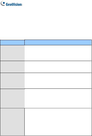
Options
Optional devices can expand your camera’s capabilities and versatility. Contact your dealer for more information.
Device
Power Adapter
GV-PA191 PoE
Adapter
GV-POE Switch
GV-Mount
Accessories
GV-WiFi Adapter
Description
The power adapter is available for all Mini Fixed Dome, Cube Camera, and Advanced Cube Camera. Contact your sales representative for the countries and areas supported.
The GV-PA191 PoE adapter is designed to provide power and network connection to the cameras over a single Ethernet cable.
The GV-POE Switch is designed to provide power along with network connection for IP devices. The GV-POE Switch is available in various models with different numbers and types of ports.
The GV-Mount Accessories provide a comprehensive lineup of accessories for installation on ceiling, wall corner and pole. For details, see GVMount Accessories Installation Guide on the Software DVD.
The GV-WiFi Adapter is a plug-and-play device designed to connect GV-MFD1501 series / 2401 series / 2501 series / 3401 series / 5301 series to wireless network. This product complies with IEEE 802.11 b/g/n (Draft 3.0) standards for wireless networking.
iv

Device
Plastic PG21
Conduit
Connector
GV-Relay V2
Description
The plastic PG21 conduit connector is used for running the wires of Target Mini Fixed Rugged Dome through a 1/2” conduit pipe.
The connector is not supported by GV-EFD2700 / 4700 Series and GV-MFD2700 / 4700 Series.
The GV-Relay V2 is supported by GV-EFD2700 Series and GV-MFD2700 / 4700 Series. The GVRelay V2 is designed to expand the voltage load of GV IP devices. It provides 4 relay outputs, and each can be set as normally open (NO) or normally closed (NC) independently as per your requirement.
v

Note for USB Storage and WiFi
Adapter
Mind the following limitations and requirements for using USB storage and GV-WiFi Adapter:
1.The USB hard drive must be of 2.5’’ or 3.5’’, version 2.0 or above.
2.The USB hard drive’s storage capacity must not exceed 2TB.
3.USB flash drives and USB hubs are not supported.
4.External power supply is required for the USB hard drive.
5.To connect a GV-WiFi Adapter, make sure it is connected before the camera is powered on.
vi
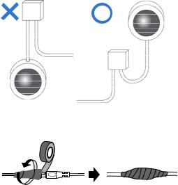
Note for Installing Camera Outdoor
When installing Mini Fixed Rugged Dome outdoor, be sure that:
1.The camera is set up above the junction box to prevent water from entering the camera along the cables.
2.Any PoE, power, audio and I/O cables are waterproofed using waterproof silicon rubber or the like.
3.The silica gel bag loses its effectiveness when the dry camera is opened. To prevent the lens from fogging up, replace the silica gel bag every time you open the camera, and conceal the gel bag in camera within 2 minutes of exposing to open air.
vii
1 Mini Fixed & Rugged Dome
Chapter 1 Mini Fixed Dome (Part I) & Mini Fixed Rugged Dome
The Mini Fixed Dome (GV-MFD) and Mini Fixed Rugged Dome (GV-MDR) are fixed, mini-sized ceiling-mount network cameras.
The GV-MDR series is designed for outdoor surveillance, conforming to IK10 and IP67 standards. The camera is adjustable in 3 axis (pan, tilt and rotate) and can be connected through PoE.
The GV-MFD series is designed for indoor surveillance. Adjustable in 2 axis (pan and tilt), the camera also supports PoE.
The super low lux models can provide color live view in near darkness and the WDR Pro models can process scenes of contrasting intensity of lights.
1

Mini Fixed Dome (GV-MFD)
|
Model No. |
|
|
Specifications |
Description |
|
|
|
|
|
|
Fixed Iris, f: 4 mm, |
1.3 MP Low Lux, |
|
GV-MFD120 |
|
|
|
F/1.5, 1/3’’ M12 |
|
|
|
|
|
H.264, Color |
||
|
|
|
|
|
Mount |
|
|
|
|
|
|
|
|
|
GV-MFD130 |
|
|
|
Fixed Iris, f: 2.54 |
1.3 MP / 2 MP / 3 |
|
|
|
|
mm, F/2.8, 1/2.5’’ |
MP / 5MP, H.264, |
|
|
GV-MFD320 |
|
|
|
||
|
|
|
|
M12 Mount |
Color |
|
|
|
|
|
|
||
|
GV-MFD1501-0F |
|
|
|
|
|
|
GV-MFD2401-0F |
|
|
|
Fixed Iris, f: 2.8 mm, |
|
|
GV-MFD2501-0F |
|
|
|
F/2.0, 1/3’’ M12 |
|
|
GV-MFD3401-0F |
|
|
|
Mount |
|
|
GV-MFD5301-0F |
|
|
|
|
|
|
GV-MFD1501-1F |
|
|
|
Fixed Iris, f: 4 mm, |
|
|
|
|
|
F/1.5, 1/3’’ M12 |
|
|
|
GV-MFD2501-1F |
|
|
|
|
|
|
|
|
|
Mount |
|
|
|
|
|
|
|
|
|
|
GV-MFD1501-2F |
|
|
|
|
|
|
GV-MFD2401-2F |
|
Fixed |
|
Fixed Iris, f: 8 mm, |
|
|
GV-MFD2501-2F |
|
Lens |
|
F/1.6, 1/3’’ M12 |
1.3 MP Super |
|
GV-MFD3401-2F |
|
|
|
Mount |
|
|
|
|
|
Low Lux / 2 MP / |
||
|
GV-MFD5301-2F |
|
|
|
|
|
|
|
|
|
|
2 MP Super Low |
|
|
GV-MFD1501-3F |
|
|
|
|
|
|
|
|
|
|
Lux / 3 MP / 5 |
|
|
GV-MFD2401-3F |
|
|
|
Fixed Iris, f: 12 mm, |
MP, H.264, Color |
|
GV-MFD2501-3F |
|
|
|
F/1.6, 1/3’’ M12 |
|
|
GV-MFD3401-3F |
|
|
|
Mount |
|
|
GV-MFD5301-3F |
|
|
|
|
|
|
GV-MFD1501-4F |
|
|
|
Fixed Iris, f: 2.1 mm, |
|
|
|
|
|
F/1.8, 1/3’’ M12 |
|
|
|
GV-MFD2401-4F |
|
|
|
|
|
|
|
|
|
Mount |
|
|
|
|
|
|
|
|
|
|
GV-MFD1501-5F |
|
|
|
|
|
|
GV-MFD2401-5F |
|
|
Fixed Iris, f: 3.8 mm, |
|
|
|
GV-MFD2501-5F |
|
|
F/1.8, 1/3’’ M12 |
|
|
|
GV-MFD3401-5F |
|
|
Mount |
|
|
|
GV-MFD5301-5F |
|
|
|
|
|
2

1 Mini Fixed & Rugged Dome
|
Model No. |
|
|
Specifications |
Description |
|
|
GV-MFD2501-6F |
|
Fixed |
|
Fixed Iris, f: 2.3mm, |
2 MP Super Low |
|
|
|
F/2.2, 1/3’’ M12 |
Lux / 3 MP WDR |
||
|
GV-MFD3401-6F |
|
Lens |
|
||
|
|
|
Mount |
Pro, H.264, Color |
||
|
|
|
|
|
||
Mini Fixed Rugged Dome (GV-MDR)
|
Model No. |
|
|
Specifications |
|
|
GV-MDR220 |
|
|
|
Fixed Iris, f: 2.54 |
|
GV-MDR320 |
|
|
|
mm, F/2.8, 1/2.5’’ |
|
GV-MDR520 |
|
|
|
M12 Mount |
|
GV-MDR1500-1F |
|
Fixed |
|
Fixed Iris, f: 2.8 |
|
GV-MDR3400-1F |
|
|
mm, F/2.0, 1/3’’ |
|
|
|
Lens |
|
||
|
GV-MDR5300-1F |
|
|
M12 Mount |
|
|
|
|
|
||
|
GV-MDR1500-2F |
|
|
|
Fixed Iris, f: 3.8 |
|
GV-MDR3400-2F |
|
|
|
mm, F/1.8, 1/3’’ |
|
GV-MDR5300-2F |
|
|
|
M12 Mount |
Description
2 MP / 3 MP / 5MP,
H.264, Color
1.3 MP super low lux / 2 MP WDR Pro / 2 MP super low lux / 3 MP WDR Pro / 5 MP, H.264, Color
3
1.1 Packing List
GV-MFD
Mini Fixed Dome
Torx Wrench
Self Tapping Screw x 2
Screw Anchor x 2
Cable stopper
2-pin terminal block (for GV-MFD120 / 130 / 320)
Short-Body RJ-45 Plug (for GV-MFD1501 series / 2401 series / 2501 series / 3401 series / 5301 series)
USB / Audio Y-cable (for GV-MFD1501 series / 2401 series / 2501 series / 3401 series / 5301 series)
Power Adapter
GV-IPCAM H.264 Software DVD
GV-Software DVD
Warranty Card
Note: The power adapter can be excluded upon request.
4

1 Mini Fixed & Rugged Dome
GV-MDR
Mini Fixed Rugged Dome
Torx Wrench
Self Tapping Screw x 2
Screw Anchor x 2
Cable stopper
Cable Connector
Installation sticker
Silica gel bag x 2
Adhesive Tape for Silica Gel Bag x 2
Ferrite core for vehicle installation
GV-IPCAM H.264 Software DVD
GV-Software DVD
Note:
1.The power adapter can be excluded upon request.
2.When purchasing GV-MDR1500 / 3400 / 5300, choose one of the two LAN connector types (for motor vehicles or for general use). For details, see LAN Connector, 1.2.3 GV-MDR.
5
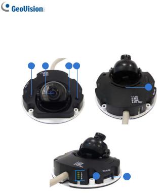
1.2 Overview
1.2.1 GV-MFD120 / 130 / 320
1 |
2 |
3 |
4 |
5
 6 7
6 7
|
|
|
|
|
Figure 1-1 |
|
|
|
|
|
|
No. |
|
|
Name |
|
Description |
1 |
|
|
Default Button |
|
Resets the camera to factory default. For |
|
|
|
details, see 1.5 Loading Factory Default. |
||
|
|
|
|
|
|
2 |
|
|
Lens |
Receives image inputs. |
|
3 |
|
|
Tilt Screw |
Loosens the screw to adjust tilt angle. |
|
4 |
|
|
Microphone |
Provides one-way audio. |
|
5 |
|
|
Pan Screw |
Loosens the screw to pan. |
|
6

1 Mini Fixed & Rugged Dome
No. |
Name |
Description |
6 |
LED Indicators |
See LED Indicators below. |
7 |
Memory Card Slot |
Inserts a micro SD card (SD/SDHC, |
|
|
version 2.0 only, Class 10) to store |
|
|
recording data. |
LED Name |
Description |
|
1. |
Link |
Turns on when the network is connected. |
2. |
ACT |
Turns on when data are being transmitted. |
3. |
PWR |
Turns on when power is on. |
4. |
SW RDY (Status) |
Turns on when the system is ready. |
7
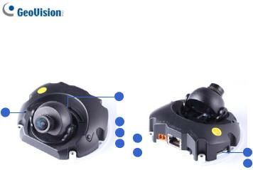
1.2.2 GV-MFD1501 Series / 2401 Series / 2501 Series / 3401 Series / 5301 Series
2
1
|
|
|
|
|
|
|
|
|
3 |
|
|
|
|
|
|
|
|
|
||
|
|
|
|
|
|
|
|
|
|
|
|
|
|
|
|
|
|
|||
|
|
|
|
|
|
|
|
|
|
4 |
6 |
|
|
|
|
|
|
|
|
|
|
|
|
|
|
|
|
|
|
|
|
|
|
|
|
|
|
|
|||
|
|
|
|
|
|
|
|
|
|
5 |
|
|
|
|
|
|
8 |
|
||
|
|
|
|
|
|
|
|
|
|
7 |
|
|
|
|
|
|
|
|||
|
|
|
|
|
|
|
|
|
|
|
|
|
|
|
|
|
|
|
||
|
|
|
|
|
|
|
|
|
|
|
|
|
|
|
||||||
|
|
|
|
|
|
|
|
|
|
|
|
|
|
|
|
|||||
|
|
|
|
|
|
|
|
|
|
|
|
|
|
|
|
|
|
|
9 |
|
|
|
|
|
|
|
|
|
Figure 1-2 |
||||||||||||
|
|
|
|
|
|
|
|
|
|
|||||||||||
|
|
|
|
|
|
|
|
|||||||||||||
No. |
|
|
Name |
|
Description |
|
|
|||||||||||||
1 |
|
|
Microphone |
Receives sound. |
|
|
||||||||||||||
2 |
|
|
Pan Screw |
Loosens the screw to pan. |
|
|
||||||||||||||
3 |
|
|
Lens |
|
Receives image inputs. |
|
|
|||||||||||||
4 |
|
|
Tilt Screw |
Loosens the screw to adjust tilt angle. |
|
|
||||||||||||||
5 |
|
|
Default Button |
|
Resets the camera to factory default. For |
|
|
|||||||||||||
|
|
|
details, see 1.5 Loading Factory Default. |
|
|
|||||||||||||||
|
|
|
|
|
|
|
|
|
|
|||||||||||
6 |
|
|
DC 5V Power Port |
|
Connects to power. |
|
|
|||||||||||||
7 |
|
|
LAN / PoE |
|
Connects to a 10/100 Ethernet or PoE. |
|
|
|||||||||||||
|
|
|
|
|
|
|
|
Inserts a micro SD card (SD/SDHC, |
|
|
||||||||||
8 |
|
|
Memory Card Slot |
|
version 2.0 only, Class 10) to store |
|
|
|||||||||||||
|
|
|
|
|
|
|
|
recording data. |
|
|
||||||||||
|
|
|
|
|
|
|
Connects to a GV-WiFi Adapter/USB hard |
|||||||||||||
9 |
|
|
USB and Audio Out |
drive and a speaker through the supplied Y |
||||||||||||||||
|
|
|
|
|
|
|
cable. |
|
|
|
|
|
|
|
|
|
||||
8
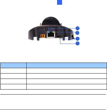
LED Name
1.Link
2.ACT
3.Status
4.Power
1 Mini Fixed & Rugged Dome
1
2
3
4
Figure 1-3
Description
Turns on (green) when the network is connected. Turns on (orange) when data are being transmitted. Turns on (red) when the system is ready.
Turns on (green) when power is on.
Note: For details on limitations and requirements of the USB port, refer to Note for USB Storage and WiFi Adapter at the beginning of this manual.
9
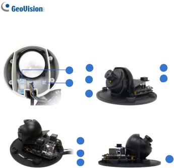
1.2.3 GV-MDR
1 |
3 |
|
|
|
|
6 |
|||
|
|
||||||||
4 |
|
|
|
|
|
|
|
7 |
|
2 |
|
|
|
|
|
|
|
||
|
|
|
|
|
|||||
|
|
|
|
|
|
|
|||
|
|
|
|
|
|
|
|
|
|
|
5 |
|
|
|
|
|
|
|
|
|
|
|
|
|
|
|
|
|
|
|
|
|
|
|
|
|
|
|
|
8 |
|
|
|
|
|
|
|
|
|
|
|
|
|
|
|
||
|
|
|
|
|
|
|
|
|
|
9 |
|
11 |
|
|
|
|
|
|
|
|
|
|
|
|
|||
|
|
|
|
|
|
|
|
|
10 |
|
|
||
|
|
|
|
|
|
|
|
|
|
||||
|
|
|
|
|
|
|
|
|
|
|
|
||
|
|
|
|
|
|
|
|
|
|
Figure 1-4 |
|
|
|
|
|
|
|
|
|
|
|
||||||
No. |
|
|
Name |
|
Description |
|
|
||||||
1 |
|
|
Silica gel bag |
Absorbs the moisture inside the camera. |
|||||||||
2 |
|
|
Conceal paper |
|
Prevents water or moisture from entering |
||||||||
|
|
|
the camera. |
|
|
||||||||
|
|
|
|
|
|
|
|
|
|
||||
3 |
|
|
Lens |
Receives image inputs. |
|
|
|||||||
4 |
|
|
Rotation Disc |
Rotates the camera lens. |
|
|
|||||||
5 |
|
|
Pan Disc |
Pans the camera lens. |
|
|
|||||||
6 |
|
|
Tilt Screw |
Loosens to tilt the camera. |
|
|
|||||||
7 |
|
Microphone |
Provides one-way audio. |
|
|
||||||||
10
1 Mini Fixed & Rugged Dome
No. |
|
|
Name |
|
Description |
8 |
|
|
Default Button |
|
Resets the camera to factory default. For |
|
|
|
details, see 1.5 Loading Factory Default. |
||
|
|
|
|
|
|
|
|
|
Power and status |
|
Turns red when the power is on. Flashes |
9 |
|
|
|
orange light twice when the system is |
|
|
|
LED |
|
||
|
|
|
|
ready. |
|
|
|
|
|
|
|
10 |
|
|
LAN LED |
|
Turns on when the network is connected. |
|
|
|
|
|
Inserts a micro SD card (SD/SDHC, |
11 |
|
|
Memory Card Slot |
|
version 2.0 only, Class 10) to store |
|
|
|
|
|
recording data. |
IMPORTANT: In case of damage and possible condensation inside the camera housing, be sure not to touch or remove the conceal paper.
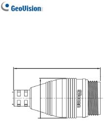
LAN Connector
Two types of LAN connector are available for GV-MDR1500 series / 3400 series / 5300 series. Select an option based on your installation environment.
1.Waterproof M12 4-Pin Female Connector
The M12 connector is used for motor vehicles.
Ø14.7 mm (0.58'')
11
2.Small Waterproof Connector
For this connector type, see 1.3.2 GV-MDR to install the supplied cable connector.
42.8mm (1.69")
ø19.6 (0.77”)
12
1 Mini Fixed & Rugged Dome
1.3 Installation
To install a Mini Fixed Dome, make sure the installing site is shielded from rain and moisture.
1.3.1 GV-MFD Series
1.Unscrew the housing cover using the supplied torx wrench.
2.Put the camera on the desired location and make 2 marks on the ceiling for screw anchors. If you want to run the cables inside the ceiling, make a round mark with a diameter of 2.5 cm.
3.Drill the marks and insert the screw anchors.
4.Secure the Mini Fixed Dome to the ceiling with the self-tapping screws.
5.Connect the camera to network and power. For details, see 1.4 Connecting the Camera.
6.Access the live view. For details, see 7.2 Accessing the Live View.
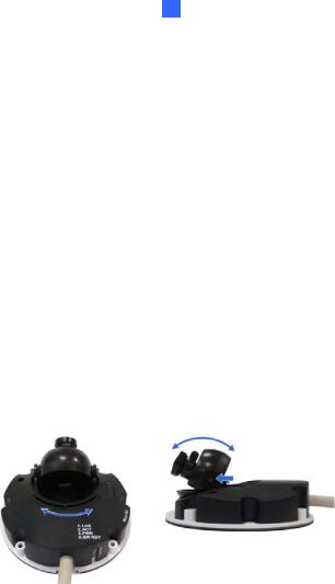
7.Adjust the angles based on the live view.
Pan Adjustment |
Tilt Adjustment |
Figure 1-6
Figure 1-5
13

8.Adjust image clarity using the GV-IP Device Utility program. For details, see 7.3 Adjusting Image Clarity.
9.Insert a Micro SD card (SD/SDHC, version 2.0 only, Class 10) into the memory card slot (No. 7, Figure 1-1).
10.Secure the housing cover using the supplied torx wrench.
11.Optionally conceal the cable opening with the supplied cable stopper.
Cable stopper
Figure 1-7
14
1 Mini Fixed & Rugged Dome
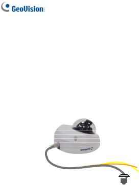
1.3.2 GV-MDR Series
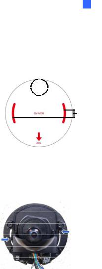
1.Paste the installation sticker on the desired location. The arrow should point toward the direction that the camera faces.
2.Drill one hole on each of the two curves for screw anchors. Drill the circle (30 mm in diameter) if you want to run the cable into the ceiling.
 30 mm
30 mm 
Drill a hole on each
Figure 1-8
3.Insert the screw anchors.
4.Unscrew the housing cover using the supplied torx wrench.
5.Secure the camera body to the ceiling with the self-tapping screws.
Figure 1-9
15
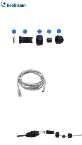
6.Install the cable connector to waterproof the cable. You should have 5 parts:
1 |
2 |
3 |
4 |
5 |
Figure 1-10
A.Prepare an Ethernet cable with the RJ-45 connector on one end only.
Figure 1-11
B.Connect the Ethernet cable to the camera cable.
C.Paste the sticker to the camera cable and slide in all the components as shown below.
Figure 1-12
16
1 Mini Fixed & Rugged Dome
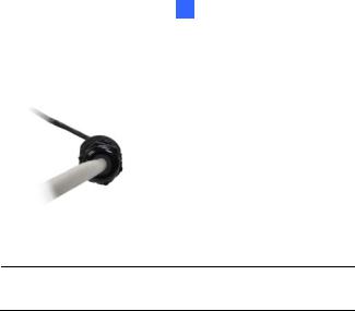
D.Move all the components toward the RJ-45 connector, fit item 4 to item 2, secure item 3 to the camera cable and finally secure item 5 to item 2 tightly.
Figure 1-13
IMPORTANT: Item 5 must be secured tightly to waterproof the cable.
7.Access the live view. For details, see 7.2 Accessing the Live View.
17
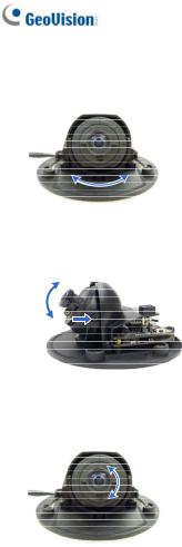
8.Adjust the angles based on the live view.
Pan Adjustment
Figure 1-14
Tilt Adjustment
Figure 1-15
Rotational Adjustment
Figure 1-16
9.Adjust image clarity using the GV-IP Device Utility program. For details, see 7.3 Adjusting Image Clarity.
10.Insert a Micro SD card (SD/SDHC, version 2.0 only, Class 10) into the memory card slot (No. 11, Figure 1-2).
18

1 Mini Fixed & Rugged Dome
11. Replace the silica gel bag.
IMPORTANT: The silica gel bag loses it effectiveness when the dry camera is opened. To prevent the lens from fogging up, replace the silica gel bag every time you open the camera, and conceal the gel bag in camera within 2 minutes of exposing to open air.
12.Secure the housing cover using the supplied torx wrench.
13.Optionally conceal the cable opening with the supplied cable stopper.
Cable stopper
Figure 1-17
19
1.4 Connecting the Camera
Refer to the wire definition and illustrations below to connect the power and network.
1.4.1 Wire Definition
GV-MFD120 / 130 / 320
The data cable provides connections for power and network access. The wires are illustrated and defined below:
|
|
|
|
|
|
|
Figure 1-18 |
|
|
|
|
|
|
|
No. |
Wire Color |
Definition |
|
|
1 |
Yellow |
DC 12V+ |
|
|
2 |
Orange |
GND |
|
|
3 |
Gray |
PoE, Ethernet |
|
|
GV-MDR Series
Power and network connectivity is provided through a PoE cable.
Wire Color |
Definition |
Gray |
PoE, Ethernet |
20
Loading...