


GV-GF Fingerprint Reader
User’s Manual
Before attempting to connect or operate this product,
please read these instructions carefully and save this manual for future use.
GF1911.1912.1921.1922-B

© 2014 GeoVision, Inc. All rights reserved.
Under the copyright laws, this manual may not be copied, in whole or in part, without the written consent of GeoVision.
Every effort has been made to ensure that the information in this manual is accurate. GeoVision, Inc. makes no expressed or implied warranty of any kind and assumes no responsibility for errors or omissions. No liability is assumed for incidental or consequential damages arising from the use of the information or products contained herein. Features and specifications are subject to change without notice.
GeoVision, Inc.
9F, No. 246, Sec. 1, Neihu Rd., Neihu District, Taipei, Taiwan Tel: +886-2-8797-8377
Fax: +886-2-8797-8335 http://www.geovision.com.tw
Trademarks used in this manual: GeoVision, the GeoVision logo and GV series products are trademarks of GeoVision, Inc. Windows and Windows XP are registered trademarks of Microsoft Corporation.
January 2014
Preface
Welcome to the GV-GF Fingerprint Reader User’s Manual.
This Manual applies to the following GV-GF Fingerprint Readers:
Product |
Version |
GV-GF1911 / 1912 |
V1.0 |
|
|
GV-GF1921 / 1922 |
V1.1 |
|
|
i

|
|
Contents |
|
Preface........................................................................... |
|
i |
|
Contents |
....................................................................... |
ii |
|
Regulatory Notices .......................................................................................................... |
v |
||
Caution........................................................................................................................... |
|
vi |
|
Installation Considerations ............................................................................................ |
vii |
||
Firmware and Software Compatibility ........................................................................... |
viii |
||
Chapter 1 Introduction ............................................... |
1 |
||
1.1 |
Packing List............................................................................................................. |
2 |
|
1.2 |
Options.................................................................................................................... |
3 |
|
1.3 |
Serial Number / MAC Address................................................................................. |
5 |
|
1.4 |
Installation ............................................................................................................... |
6 |
|
Chapter 2 Connecting GV-AS Controller .................. |
8 |
||
2.1 |
Connecting through Wiegand Interface.................................................................... |
8 |
|
|
2.1.1 |
Physical Connection...................................................................................... |
8 |
|
2.1.2 |
Software Configuration.................................................................................. |
9 |
2.2 |
Connecting through RS-485 Interface .................................................................... |
10 |
|
|
2.2.1 |
Physical Connection.................................................................................... |
10 |
|
2.2.2 |
Software Configuration................................................................................ |
11 |
2.3 |
Connecting through TCP/IP Interface ..................................................................... |
12 |
|
|
2.3.1 |
Physical Connection.................................................................................... |
12 |
|
2.3.2 |
Accessing the Web Interface....................................................................... |
14 |
|
2.3.3 |
Software Configuration................................................................................ |
15 |
Chapter 3 Fingerprint Only Mode............................. |
18 |
||
3.1 |
Enrolling Fingerprints.............................................................................................. |
18 |
|
|
3.1.1 |
Enrolling Fingerprints Locally ...................................................................... |
19 |
|
3.1.2 |
Enrolling Fingerprints Remotely (GV-GF1921 / 1922 Only) ......................... |
22 |
3.2 |
Uploading Fingerprints to Fingerprint Readers ....................................................... |
25 |
|
ii
3.3 |
Uploading Fingerprints Using Door Groups ............................................................ |
29 |
3.4 |
Using the Fingerprint Reader.................................................................................. |
30 |
Chapter 4 Card + Fingerprint Mode.......................... |
31 |
|
4.1 |
Enrollment .............................................................................................................. |
31 |
4.2 |
Deletion.................................................................................................................. |
34 |
4.3 |
Using the Fingerprint Reader.................................................................................. |
35 |
Chapter 5 Card Only Mode........................................ |
36 |
|
5.1 |
Enrollment .............................................................................................................. |
37 |
5.2 |
Deletion.................................................................................................................. |
38 |
5.3 |
Using the Fingerprint Reader.................................................................................. |
38 |
Chapter 6 Connecting an Alarm Device................... |
39 |
|
6.1 |
GV-GF1911 / 1912 ................................................................................................. |
39 |
6.2 |
GV-GF1921 / 1922 ................................................................................................. |
40 |
Chapter 7 A Standalone Fingerprint Reader ........... |
41 |
|
7.1 |
Physical Connection............................................................................................... |
41 |
7.2 |
Enabling the Local Mode ........................................................................................ |
42 |
7.3 |
Fingerprints and Card Enrollment........................................................................... |
43 |
|
7.3.1 Fingerprint Only Mode................................................................................. |
43 |
Chapter 8 Web Interface for GV-GF1921 / 1922....... |
44 |
|
8.1 |
Network Settings .................................................................................................... |
44 |
8.2 |
Other Settings ........................................................................................................ |
47 |
8.3 |
Firmware Update.................................................................................................... |
50 |
8.4 |
Account Settings .................................................................................................... |
50 |
Chapter 9 Upgrading Firmware ................................ |
51 |
|
9.1 |
GV-GF1911 / 1912 ................................................................................................. |
51 |
|
9.1.1 Connecting to a Computer .......................................................................... |
51 |
|
9.1.2 Installing Software....................................................................................... |
53 |
9.1 |
GV-GF1921 / 1922 ................................................................................................. |
55 |
|
9.2.1 Upgrading Firmware through the Web Interface .......................................... |
55 |
|
|
iii |

Chapter 10 GV-Net Module Utility ............................ |
57 |
Specifications ............................................................. |
59 |
LED Indicator .............................................................. |
62 |
iv
Regulatory Notices
 FCC Notice
This equipment has been tested and found to comply with the limits for a Class A digital device, pursuant to part 15 of the FCC Rules. These limits are designed to provide reasonable protection against harmful interference when the equipment is operated in a commercial environment.
Class A
This equipment generates, uses, and can radiate radio frequency energy and, if not installed and used in accordance with the instruction manual, may cause harmful interference to radio communications. Operation of this equipment in a residential area is likely to cause harmful interference in which case the user will be required to correct the interference at their own expense.
 CE Notice
This is a Class A product. In a domestic environment, this product may cause radio interference in which case the user may be required to take adequate measures.
 RoHS Compliance
The Restriction of Hazardous Substances (RoHS) Directive is to forbid the use of hazardous materials of production. To meet the RoHS Directive requirements, this product is made to be RoHS compliant.
 WEEE Compliance
This product is subject to the Waste Electrical and Electronic Equipment (WEEE) Directive and made compliant with the WEEE requirements.
v

Caution
The fingerprint reader is designed only for indoor usage. Avoid exposing to sunshine or rains.
To keep the fingerprint reader in good working condition, it is recommended to have regular maintenance and physical cleaning of the reader.
vi
Installation Considerations
Note the distance limitations for Wiegand and RS-485 communications:
Wiegand interface: 30 meters (98.43 feet)
RS-485 interface: 600 meters (1968.50 feet)
Recommended RS-485 cable: standard 485 cable (a twisted pair of 24 AWG wires)
vii

Firmware and Software Compatibility
The GV-AS Controller, GV-EV48 Controller and GV-ASManager compatible with GVGF1911 / 1912 / 1921 / 1922 are listed below.
|
GV-GF1911 / 1912 |
GV-GF1921 / 1922 |
|
|
|
GV-ASManager |
V4.0 or later |
|
|
|
|
GV-AS100 / 110 / 120 |
V1.06 or later |
N/A |
|
|
|
GV-AS400 |
V1.04 or later |
N/A |
|
|
|
GV-AS210 / 810 |
V1.0 or later |
V1.1 or later |
|
|
|
GV-AS410 |
V1.1 or later |
|
|
|
|
GV-EV48 Elevator Controller |
V1.0 or later |
|
|
|
|
viii
1 Introduction
Chapter 1 Introduction
The fingerprint reader can work with GV-AS / GV-EV Controller and GV-ASManager to create a complete access control system. Three types of operation modes are supported: Card + Fingerprint, Fingerprint Only and Card Only.
Card + Fingerprint Mode
With the fingerprint reader only, you can enroll and manage users through the supplied Manager Enroll Card and Delete Card, along with optional MIFARE cards.
The fingerprint templates are stored in the user card. The user gains access by scanning both his/her finger and the card. The reader compares the presented finger with digital template stored in the card. If the finger is successfully authenticated, a signal is sent to momentarily activate the door relay of the controller.
Fingerprint Only Mode
The fingerprints are enrolled through a GV-GF1911 reader installed on the computer running the GV-ASManager software using RS485 connection or through a GV-GF1921 / 1922 reader using TCP/IP connection. The fingerprint data are distributed through GV-ASManager to the assigned fingerprint readers installed on GV-AS / GV-EV Controllers for access control.
Card Only Mode
This mode requires the users to present their cards only to be granted access.
Note: GV-GF1921 / 1922 can also work as a standalone device. For details, see 7. A Standalone Fingerprint Reader.
1

1.1 Packing List
If any of the items are missing or damaged, contact your dealer to arrange a replacement.
GV-GF1911 / 1912
Fingerprint reader x 1 (with a cable of 100 cm / 3.28 feet)
Manager Enroll Card x 1
Manager Delete Card x 1
Self-Tapping Screw (M3 x 6L) x 2
Self-Tapping Screw (M4 x 15L) x 3
Plastic Screw Anchor x 4
Buzzer Hole Plate
Security Torx
Software CD
GV-GF1921 / 1922
Fingerprint reader x 1
Manager Enroll Card x 1
Manager Delete Card x 1
Mounting Plate x 1
Standard Screw x 2
Plastic Screw Anchor x 2
Security Screw x 1
Torx Wrench x 1
Connector Wire x 1
Software CD
2
1 Introduction
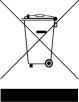
1.2 Options
You can order the following optional accessories:
GV-AS ID Card & For Card + Fingerprint Mode, the GV-AS ID F Card or GV-AS ID GV-AS ID Tag F Tag is required. You can find the serial number Fxxx,xxxxx at
the bottom right corner of the card, or at the center of the tag.
|
For Card Only Mode, both the GV-AS ID F Card / Tag and the |
|
GV-AS ID Card / Tag are supported, but the GV-AS ID F Card / |
|
Tag cannot contain any fingerprint data. |
GV-HUB V2 |
The GV-Hub V2 adds four RS-232/RS-485 serial ports through |
|
the computer’s USB port, allowing connection between the |
|
fingerprint reader and the computer. |
GV-COM V2 |
The GV-COM V2 can convert the standard RS-232 signal, |
|
through USB connector, to RS-485 signal, allowing connection |
|
between the fingerprint reader and the computer. |
3

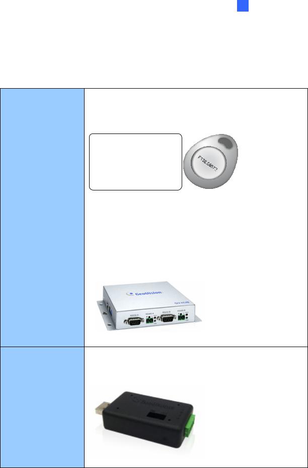
GV-NET/IO Card V3.1 The GV-NET/IO Card is a RS-485 / RS-232 interface converter GV-NET/IO Card V3.2 that provides 4 inputs and 4 relay outputs. Using the GV-NET/IO
Card, you can connect the fingerprint reader to the computer.
PC Service Package The package includes a USB cable for connecting the fingerprint reader to a computer and a reader mount to hold the reader for fingerprint enrollment. See 7. Upgrading Firmware later.
Note:
1.For Card + Fingerprint Mode, GV-GF Fingerprint Readers can only work with GeoVision’s user cards and tags.
2.For Card + Fingerprint Mode, be sure that your user card has the serial number starting with the letter F; otherwise, you cannot record the fingerprints to the user card.
3.GV-HUB V2, GV-COM V2, GV-NET/IO Card and PC Service Package are only compatible with GV-GF1911 / 1912.
4
1 Introduction
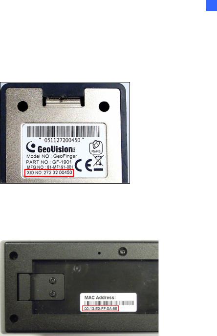
1.3 Serial Number / MAC Address
To find the serial number of GV-GF1911 / 1912, see the XID number on the back of fingerprint reader.
Figure 1-1
For GV-GF1921 and GV-GF1922, you can find the MAC address on the back of the device.
Figure 1-2
You can also find the serial number (for GV-GF1911 / 1912) or the MAC address (for GVGF1921 / 1922) using the GV-Net Module Utility supplied on the software CD. For details to use the utility, see GV-Net Module Utility, Chapter 10.
5
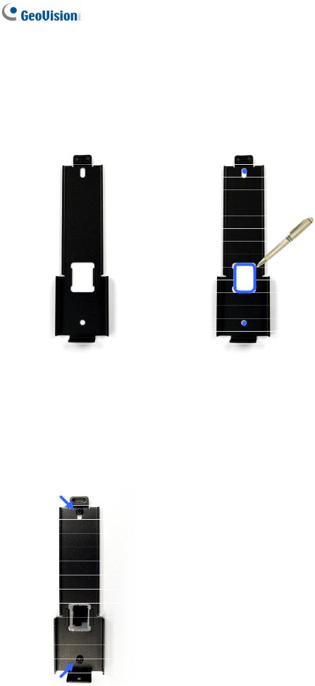
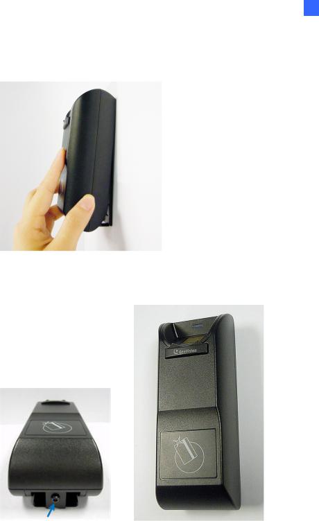
1.4 Installation
Follow the steps below to install the GV-GF1921 / 1922 on wall.
1.Place the mounting plate on the wall as illustrated below.
Figure 1-3
2.Mark the location of the 2 holes and the rectangle as labeled above.
3.Drill the rectangle to create a space for running the cables and wires.
4.At the 2 dots, drill a hole slightly smaller than the plastic screw anchors provided.
5.Insert the 2 plastic screw anchors in the drilled holes.
6.Place the mounting plate on the wall and secure with the 2 standard screws provided.
Figure 1-4
6
1 Introduction
7.Place fingerprint reader on the mounting plate and thread the cables through the rectangular hole.
Figure 1-5
8.Secure the security screw on the bottom.
Figure 1-6
7
Chapter 2 Connecting GV-AS Controller
Depending on the model of the fingerprint reader, three types of communication links are provided: Wiegand, RS-485 and TCP/IP (LAN).
2.1 Connecting through Wiegand Interface
Supported models: GV-GF1911 / 1912.
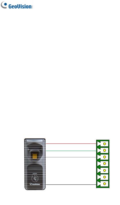
2.1.1 Physical Connection
The fingerprint reader is connected with an unshielded 9-wire cable of 100 cm / 3.28 feet. Connect these 4 unshielded wires to the assigned pins on the Wiegand interface of the GVAS Controller: Red, Black, White and Green wires.
Figure 2-1
The table below shows the wire assignments of the fingerprint reader used for Wiegand connection.
Wire |
Red |
Black |
White |
Green |
Yellow |
Blue |
Orange |
Brown |
Silver |
|
|
|
|
|
|
|
|
|
|
Function |
12V |
GND |
Data-1 |
Data-0 |
N/C |
N/C |
N/C |
N/C |
N/C |
|
|
|
|
|
|
|
|
|
|
For the wiring of extending distance it is recommended to use the standard RS-485 cable (a twisted pair of 24 AWG wires). The maximum distance of the Wiegand output cable should be restricted to a length of 30 meters (98.43 feet).
8
2 Installation
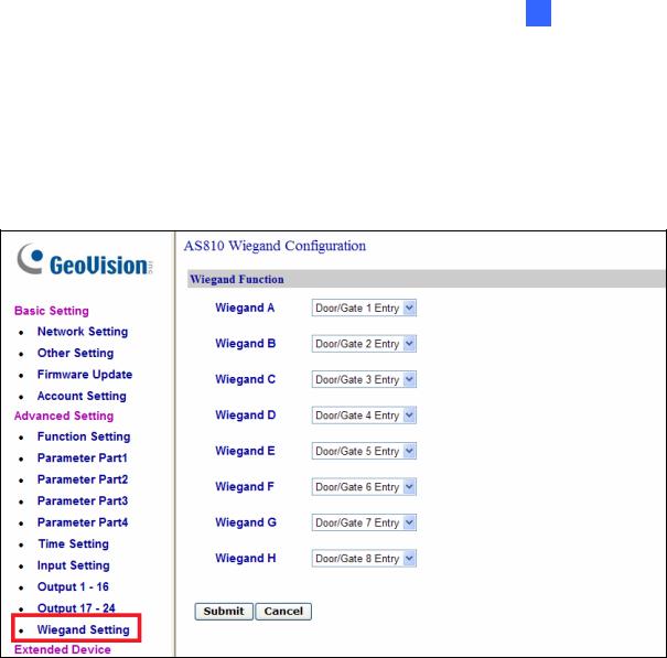
2.1.2 Software Configuration
To define the fingerprint reader connected to the GV-AS Controller. On the Web interface of GV-AS Controller, click Wiegand Setting in the left menu. The Wiegand Configuration page appears. Select the function, e,g. Door/Gate 1 Entry, that the fingerprint reader is used for, and click Submit.
Figure 2-2
9
2.2 Connecting through RS-485 Interface
Supported models: GV-GF1911 / 1912.
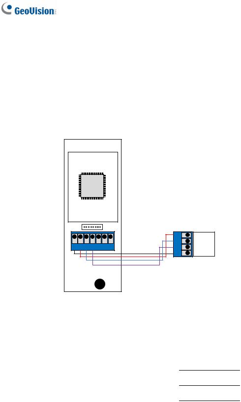
2.2.1 Physical Connection
Use the terminal block on the above four reader models for RS-485 connection to the GV-AS Controller.
VIN GND T- T+ NC COM NO
GND RS485 - RS485 + 12V
GV-AS Controller
GV-GF1911 / 1912
Figure 2-3
The table below shows the pin assignments of the fingerprint reader used for RS-485 connection.
Pin |
VIN |
GND |
T- |
T+ |
|
|
|
|
|
Function |
12V |
GND |
RS-485 - |
RS-485 + |
|
|
|
|
|
10
2 Installation
2.2.2 Software Configuration
To define the fingerprint reader connected to the GV-AS Controller, on the Web interface of GV-AS Controller, click Extended Reader in the left menu. The Extended Reader Configuration page appears.
Figure 2-4
Type Serial Number of your fingerprint reader (See 1.3 Serial Number / MAC Address), and select Function that the fingerprint reader is used for, and click Submit. If the fingerprint reader is detected, the Connection Status field will be green.
IMPORTANT: For RS-485 connection, make sure to check the RS485 box before the serial number to establish connection.
11
2.3 Connecting through TCP/IP Interface
Supported models: GV-GF1911 / 1912 / 1921 / 1922
Note: The GV-GF1921 / 1922 can also work as a standalone device without connecting to a GV-AS Controller. For details, see 7. A Standalone Fingerprint Reader.
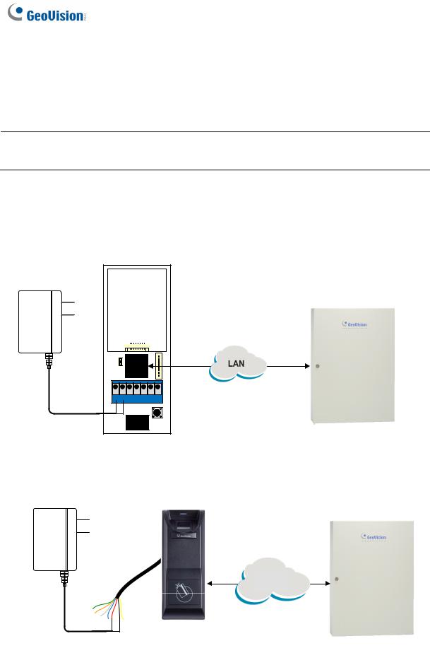
2.3.1 Physical Connection
The fingerprint reader and GV-AS Controller can be physically connected through LAN. Prepare a 12V DC power adapter to connect the fingerprint reader to a power source.
Figure 2-5
Figure 2-6
12
 Loading...