


 Loading...
GV-IP LPR Camera 5R /
GV-Hybrid LPR Camera 10R
User's Manual
Before attempting to connect or operate this product,
please read these instructions carefully and save this manual for future use. |
LPRCAM5RV10-10RV102-A |
|

© 2013 GeoVision, Inc. All rights reserved.
Under the copyright laws, this manual may not be copied, in whole or in part, without the written consent of GeoVision.
Every effort has been made to ensure that the information in this manual is accurate. GeoVision, Inc. makes no expressed or implied warranty of any kind and assumes no responsibility for errors or omissions. No liability is assumed for incidental or consequential damages arising from the use of the information or products contained herein. Features and specifications are subject to change without notice.
GeoVision, Inc.
9F, No. 246, Sec. 1, Neihu Rd., Neihu District, Taipei, Taiwan Tel: +886-2-8797-8377
Fax: +886-2-8797-8335 http://www.geovision.com.tw
Trademarks used in this manual: GeoVision, the GeoVision logo and GV series products are trademarks of GeoVision, Inc. Windows and Windows XP are registered trademarks of Microsoft Corporation.
September 2013
Preface
Welcome to the GV-Hybrid LPR Camera 10R / GV-IP LPR Camera 5R User’s Manual.
The GV-IP LPR Camera has a series of models designed to meet different needs. This manual is designed for the following models and firmware versions:
Models |
Firmware Version |
|
|
GV-Hybrid LPR Camera 10R |
1.02 |
|
|
GV-IP LPR Camera 5R |
1.0 |
|
|
i

Contents
Naming Definition..................................................................................................... |
v |
|||
Options |
.................................................................................................................... |
|
|
v |
Note for Connecting to GV-System......................................................................... |
v |
|||
Note for Installing Camera Outdoor ....................................................................... |
vi |
|||
Chapter 1 |
Introduction........................................................................................... |
1 |
||
1.1 |
GV-Hybrid LPR Camera 10R.................................................................................... |
1 |
||
|
1.1.1 |
Features........................................................................................................ |
2 |
|
|
1.1.2 |
System Requirements .................................................................................. |
3 |
|
|
1.1.3 |
Packing List .................................................................................................. |
4 |
|
|
1.1.4 |
Overview....................................................................................................... |
5 |
|
|
1.1.5 |
Device Installation......................................................................................... |
6 |
|
|
1.1.6 |
Connecting the Camera.............................................................................. |
10 |
|
1.2 |
GV-IP LPR Camera 5R........................................................................................... |
12 |
||
|
1.2.1 |
Features...................................................................................................... |
13 |
|
|
1.2.2 |
System Requirements ................................................................................ |
14 |
|
|
1.2.3 |
Packing List ................................................................................................ |
15 |
|
|
1.2.4 |
Overview..................................................................................................... |
16 |
|
|
1.2.5 |
Device Installation....................................................................................... |
17 |
|
|
1.2.6 |
Connecting the Camera.............................................................................. |
18 |
|
|
1.2.7 |
Adjusting the Angles ................................................................................... |
19 |
|
|
1.2.8 Replacing the Silica Gel Bag ...................................................................... |
22 |
||
|
1.2.9 Installing the Sun-Shield Cover .................................................................. |
23 |
||
Chapter 2 |
Getting Started.................................................................................... |
24 |
||
2.1 |
Looking Up the IP Address ..................................................................................... |
24 |
||
2.2 |
Accessing Your Surveillance Images...................................................................... |
27 |
||
2.3 |
Configuring the Basics............................................................................................ |
28 |
||
Chapter 3 Guest Mode and Live View Panel...................................................... |
29 |
|||
3.1 |
The Live View Window ........................................................................................... |
30 |
||
3.2 |
The Control Panel of the Live View Window .......................................................... |
32 |
||
3.3 |
Snapshot of a Live Video........................................................................................ |
35 |
||
3.4 |
Video Recording ..................................................................................................... |
35 |
||
3.5 |
Picture-in-Picture and Picture-and-Picture View..................................................... |
36 |
||
3.6 |
Alarm Notification ................................................................................................... |
38 |
||
3.7 |
Video and Audio Configuration ............................................................................... |
39 |
||
3.8 |
Remote Configuration............................................................................................. |
40 |
||
3.9 |
Camera Name Display ........................................................................................... |
40 |
||
ii
3.10 Image Enhancement ............................................................................................ |
40 |
Chapter 4 Administrator Mode............................................................................ |
41 |
||
4.1 |
Video & Motion ....................................................................................................... |
43 |
|
|
4.1.1 |
Video Settings............................................................................................. |
44 |
|
4.1.2 |
Motion Detection......................................................................................... |
49 |
|
4.1.3 |
Privacy Mask .............................................................................................. |
50 |
|
4.1.4 |
Text Overlay................................................................................................ |
51 |
|
4.1.5 |
Tampering Alarm......................................................................................... |
52 |
4.2 |
Events & Alerts ....................................................................................................... |
54 |
|
|
4.2.1 |
E-mail.......................................................................................................... |
55 |
|
4.2.2 |
FTP ............................................................................................................. |
57 |
|
4.2.3 |
Center V2.................................................................................................... |
59 |
|
4.2.4 |
VSM ............................................................................................................ |
61 |
|
4.2.5 |
Backup Center ............................................................................................ |
63 |
|
4.2.6 GV-Video Gateway / GV-Recording Server ................................................ |
65 |
|
|
4.2.7 |
ViewLog ...................................................................................................... |
67 |
|
4.2.8 |
RTSP .......................................................................................................... |
68 |
4.3 |
Monitoring............................................................................................................... |
69 |
|
|
4.3.1 GV-Hybrid LPR Camera 10R...................................................................... |
69 |
|
|
4.3.2 GV-IP LPR Camera 5R............................................................................... |
70 |
|
4.4 |
Recording Schedule ............................................................................................... |
71 |
|
|
4.4.1 |
Recording Schedule Settings ..................................................................... |
71 |
4.5 |
Network .................................................................................................................. |
72 |
|
|
4.5.1 |
LAN Configuration ...................................................................................... |
72 |
|
4.5.2 |
Advanced TCP/IP ....................................................................................... |
74 |
|
4.5.3 |
IP Filtering................................................................................................... |
78 |
|
4.5.4 |
SNMP Settings ........................................................................................... |
79 |
4.6 |
Management........................................................................................................... |
81 |
|
|
4.6.1 Date and Time Settings .............................................................................. |
81 |
|
|
4.6.2 |
GPS Maps Settings .................................................................................... |
83 |
|
4.6.3 |
Storage Settings ......................................................................................... |
85 |
|
4.6.4 |
User Account .............................................................................................. |
88 |
|
4.6.5 |
Log Information........................................................................................... |
89 |
|
4.6.6 |
System Log................................................................................................. |
90 |
|
4.6.7 |
Tools ........................................................................................................... |
92 |
|
4.6.8 |
Language.................................................................................................... |
94 |
Chapter 5 Advanced Applications ...................................................................... |
95 |
5.1 Upgrading System Firmware .................................................................................. |
95 |
iii

|
5.1.1 Using the Web Interface ............................................................................. |
96 |
|
|
5.1.2 Using the GV-IP Device Utility .................................................................... |
97 |
|
5.2 |
Backing Up and Restoring Settings...................................................................... |
100 |
|
5.3 |
Restoring to Factory Default Settings................................................................... |
102 |
|
|
5.3.1 Using the Web Interface ........................................................................... |
102 |
|
|
5.3.2 Directly on the Camera ............................................................................. |
102 |
|
5.4 |
Verifying Watermark ............................................................................................. |
103 |
|
|
5.4.1 |
Accessing AVI Files .................................................................................. |
103 |
|
5.4.2 |
Running Watermark Proof ........................................................................ |
103 |
|
5.4.3 The Watermark Proof Window.................................................................. |
104 |
|
Chapter 6 DVR Configurations ......................................................................... |
105 |
|
6.1 |
Setting Up IP Cameras......................................................................................... |
107 |
|
6.1.1 Customizing Camera Settings .................................................................. |
110 |
6.2 |
Remote Monitoring with Multi View ...................................................................... |
112 |
6.3 |
Remote Monitoring with E-Map ............................................................................ |
114 |
Chapter 7 CMS Configurations .......................................................................... |
116 |
|
7.1 |
Center V2 ............................................................................................................. |
116 |
7.2 |
VSM...................................................................................................................... |
118 |
7.3 |
Dispatch Server .................................................................................................... |
119 |
Chapter 8 Smart Device Connection ..................................................................... |
120 |
||
8.1 |
Android ................................................................................................................. |
121 |
|
|
8.1.1 Connecting to the Camera........................................................................ |
121 |
|
|
8.1.2 |
Accessing Live View ................................................................................. |
123 |
8.2 |
Apple |
.................................................................................................................... |
125 |
|
8.2.1 ........................................................................Connecting to the Camera |
126 |
|
|
8.2.2 ................................................................................. |
Accessing Live View |
127 |
Specifications ....................................................................................................... |
129 |
GV-Hybrid LPR Camera 10R ........................................................................................ |
129 |
GV-IP LPR Camera 5R ................................................................................................. |
133 |
Appendix ............................................................................................................... |
136 |
A. The CGI Command................................................................................................... |
136 |
B. RTSP Protocol Support............................................................................................. |
137 |
C. Settings for Internet Explorer 8 or later..................................................................... |
138 |
iv

Naming Definition
GeoVision Analog and Digital Video Recording Software. The
GV-System GV-System also refers to Multicam System, GV-NVR System, GV-DVR System and GV-Hybrid DVR System at the same time.
Options
Optional devices can expand your camera’s capabilities and versatility. Contact your dealer for more information.
|
Device |
|
|
Description |
|
|
|
|
|
|
GV-PA191 PoE |
|
|
The GV-PA191 PoE adapter is designed to provide power and |
|
|
|
network connection to the cameras over a single Ethernet cable. The |
|
|
Adapter |
|
|
|
|
|
|
GV-PA191 PoE adapter is only available for GV-IP LPR Camera 5R. |
|
|
|
|
|
|
|
|
|
|
The GV-Mount Accessories allows you to install GV-Hybrid LPR |
|
|
|
|
|
|
GV-Mount |
|
|
Camera 10R / GV-IP LPR Camera 5R on the wall corner and pole. |
|
|
|
For details, see Installing the Arctic Box Camera / Installing the Bullet |
|
|
Accessories |
|
|
|
|
|
|
Camera, GV-Mount Accessories Installation Guide on the GV-IP LPR |
|
|
|
|
|
|
|
|
|
|
Camera Software DVD. |
|
|
|
|
|
Note for Connecting to GV-System
The GV-Hybrid LPR Camera 10R / GV-IP LPR Camera 5R is designed to work with and record on GV-System, a hybrid or digital video management system.
Once the camera is connected to the GV-System, the resolution set on the GV-System will override the resolution set on the camera’s Web interface. You can only change the resolution settings through the Web interface when the connection to the GV-System is interrupted.
v

Note for Installing Camera Outdoor
When installing the GV-Hybrid LPR Camera 10R / GV-IP LPR Camera 5R outdoor, mind the following:
1.Set the camera above the junction box to prevent water from entering the camera along the cables.
2.Waterproof the PoE, power and TV-out cables with waterproof silicon rubber or the like.
3.To prevent the lens from fogging up, replace the silica gel bag every time you open the camera, and conceal the gel bag in camera within 2 minutes of exposing to open air. The silica gel bag loses it effectiveness when the dry camera is opened.
4.For each newly replaced silica gel bag, allow it to absorb moisture for at least 5 hours before operating the camera.
5.The camera casing can be hot due to its IR LED. Make sure you unplug the power cable and allow the camera casing to cool down before handling the camera.
vi

Chapter 1 Introduction
1.1GV-Hybrid LPR Camera 10R
The GV-Hybrid LPR Camera 10R is a 1.3 MP B/W network camera designed solely for recognition of reflective license plates on vehicles traveling at 120 km/hr (75 mph) or less. With its high-power LEDs and intelligent IR, the camera is able to automatically adjust its shutter speed to the scene and produce clear license plate capture under low-light conditions. Under certain conditions, the GV-Hybrid Camera 10R can capture up to two lanes in a single shot. It is also able to work in environments with extreme temperatures from as low as -40°C (-40°F) up to 50°C (122°F).
The GV-Hybrid LPR Camera 10R can be easily configured through its Web interface and you can record and play back recordings using the free GV-NVR software included in the standard package.

1.1.1Features
1.3 megapixel B/W progressive scan CMOS
Dual streams from MJPEG or H.264
Up to 30 fps at 1280 x 1024
Recognition for reflective License Plate only
Maximum Speed 120 km/h (75 mph)
Ingress protection (IP67)
Vandal Resistance (IK10)
Built-in heater and fan
Support for TV-out
Two-way audio
Defog
Motion detection
Tampering alarm
Privacy mask
Text overlay
IP address filtering
Power supplied through PoE (IEEE 802.3 at)
Support for iPhone, iPad, Android and 3GPP
ONVIF (Profile S) conformant
31 languages on Web interface
2
1 Introduction
1.1.2System Requirements
To access the camera functions and settings through Web browser, ensure your PC is in good network connection and use one of the following Web browsers:
Microsoft Internet Explorer 7.x or later
Google Chrome
Mozilla Firefox
Safari
Note:
1.For users of Internet Explorer 8 or later, additional settings are required. For details, see Appendix C.
2.With non-IE browsers,
A.Motion Detection, Text Overlay, two-way audio and GPS map settings are not supported.
B.The Play function is only available on the live view window (Figure 3-2).
C.RTSP streaming must be kept as enabled. For more details, see 4.3.8 RTSP / 3GPP.
3
1.1.3Packing List
GV-Hybrid LPR Camera 10R
Screw Anchor x 4
Screw x 4
Washer x 4
Big Torx Wrench
Small Torx Wrench
Sun-Shield Cover x 1
Silica Gel Bag x 2 (1 already installed)
Sticker x 2
GV-PA481 PoE Adapter
GV-PA481 Power Cord
GV-LPR Capture Dongle
GV-IP LPR Camera Software CD
GV-NVR Software DVD
GV-ASManager Software DVD
4
1 Introduction
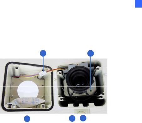
1.1.4Overview
To access the functional panel of the GV-Hybrid LPR Camera 10R, follow the section below to remove its camera cover first.
1 |
2 |
|
|
|
|
|
|
|
|
|
|
|
|
|
|
|
|
|
|
|
|
|
|
3 |
4 |
5 |
|||
|
|
|
Figure 1-1 |
|
|
|
|
|
|
|
|
||
No. |
Name |
Description |
|
|
||
1 |
IR power plug |
Supplies power to the built-in IR LEDs. |
||||
|
|
|
||||
2 |
Status LED |
Turns on when the unit is ready for use. |
||||
|
|
|
||||
3 |
Silica gel bag |
Keeps the camera housing dry. |
||||
|
|
|
||||
4 |
Zoom Screw |
Adjusts the zoom of the camera. |
||||
|
|
|
||||
5 |
Focus Screw |
Adjusts the focus of the camera. |
||||
|
|
|
|
|
|
|
5

1.1.5Device Installation
1.1.5.1Installation Guidelines
To produce quality image and to avoid software recognition errors, make sure you adhere to the guidelines when installing your GV-Hybrid LPR Camera 10R. See GV-LPR Camera Installation Guide.
1.1.5.2Installing the Camera
After you have read through the installation guides and chosen an installation site, follow the steps below to install the GV-Hybrid LPR Camera 10R.
1.Mark the installation site and drill four holes for screw anchors.
2.Insert the supplied screw anchors.
3.Secure the camera to the wall using the supplied washers and screws.
Figure 1-2
4.Connect the camera to the network and supply power via the PoE cable. See 1.6 Connecting the Camera.
5.Access the live view. See 2.1 Accessing the Live View.
6
1 Introduction
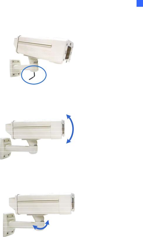
6.Based on the live view, adjust the angle of the camera. Loosen the indicated screw with the supplied big torx wrench and adjust the joint.
Figure 1-3
Tilt Adjustment
Figure 1-4
Pan Adjustment
Figure 1-5
7

7.Based on the live view, adjust the focus and zoom of the camera. A. Unscrew the cover with the supplied small torx wrench.
Figure 1-6
B. Hold the connectors and unplug them.
Figure 1-7
Important:
1.Unscrew and remove the cover carefully. Pulling the cover off may cause damages to the inner wiring of the camera.
2.To prevent the live view from being darkened when the cover is removed, see LPR Setting in 4.1.1 Video Setting.
C.Adjust the focus and zoom.
Figure 1-8
8
1 Introduction
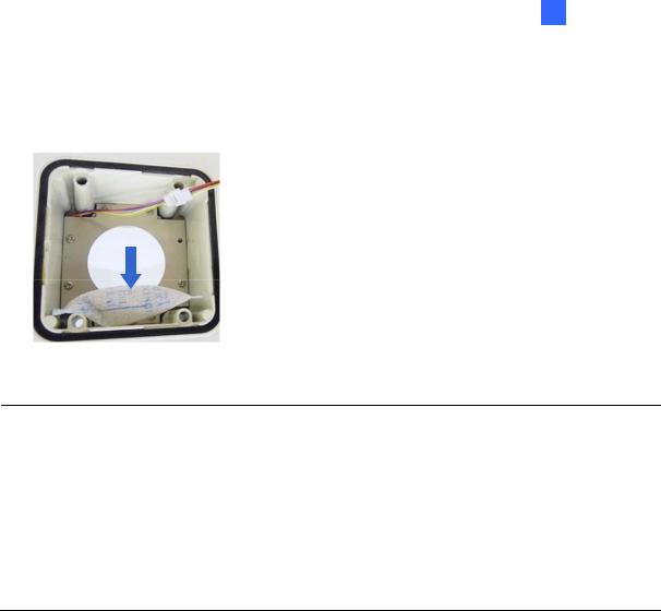
8.Replace the silica gel bag. Paste the sticker to the front side of the silica gel bag. Press the sticker several times to make sure it adheres properly. Paste the silica gel bag to the indicated place.
Figure 1-9
Important:
1.Be sure that the silica gel bag is concealed in the camera housing within 2 minutes of exposing to open air.
2.To prevent the lens from fogging up, you must replace the silica gel bag every time you open the camera. The gel bag loses its effectiveness when the dry camera is opened.
3.For each newly replaced silica gel bag, allow it to absorb moisture for at least 5 hours before operating the camera.
9.Refer to step 7 to plug the connectors and secure the camera cover.
9
1.1.6Connecting the Camera
Follow the steps below to connect your GV-Hybrid LPR Camera 10R.
1.Optionally connect a speaker to the green RCA wire and an external microphone to the pink RCA wire.
2.Optionally connect a monitor to the black BNC wire. Enable the TV-Out function by selecting the correct signal format at the TV Out field on the Web interface. See 4.1.1 Video Settings.
3.Connect the camera’s cable to the GV-PA481 PoE adapter as illustrated below. The power and network will be supplied simultaneously.
Figure 1-10
4.When the status LED of the camera is on, .you are ready to access the live view, adjust the image clarity and configure the basics. See Getting Started, Chapter 2.
10

1 Introduction
1.1.6.1Wire Definition
|
|
|
|
|
|
|
|
|
|
Figure 1-11 |
|
|
|
|
|
|
|
|
|
|
|
|
|
No. |
Wire Color |
|
Definition |
|
|
|
|
1 |
Black (thick) |
|
PoE |
|
|
|
|
|
|
|
|
|
|
|
|
2 |
Black BNC |
|
TV out |
|
|
|
|
|
|
|
|
|
|
|
|
3 |
Green RCA |
|
Audio Out |
|
|
|
|
|
|
|
|
|
|
|
|
4 |
Pink RCA |
|
Audio In |
|
|
|
|
|
|
|
|
|
|
|
|
11

1.2GV-IP LPR Camera 5R
Ideal for parking lot installation, the GV-IP LPR Camera 5R is a 1.3 MP B/W network camera designed for recognition of reflective license plates on vehicles traveling at 60 km/hr (37 mph) or less. With its multiple LEDs and intelligent IR, the camera is able to automatically adjust its shutter speed to the scene and produce clear license plate capture under low-light conditions. The motorized varifocal lens take the advantage of its motorized focus / zoom in that the user can remotely adjust the focus and zoom through the Web interface. It is weather proof (IP67) and also able to work in environments with temperatures ranging from -10°C (14°F) to 50°C (122°F).
The GV-IP LPR Camera 5R can be easily configured through its Web interface and you can record and play back recordings using the free GV-NVR software included in the standard package.
12
2 Getting Started
1.2.1Features
1.3 megapixel B/W progressive scan CMOS
Motorized varifocal lens for remote focus / zoom adjustment
Dual streams from MJPEG or H.264
Up to 30 fps at 1280 x 1024
Maximum Speed 60 km/h (37 mph)
Recognition for reflective License Plate only
Ingress protection (IP67)
Vandal Resistance (IK10)
Built-In 12 IR LEDs
Built-in fan
Defog
Motion detection
Privacy mask
Text Overlay
IP address filtering
Power supplied through PoE (IEEE 802.3 at)
Support for iPhone, iPad, Android and 3GPP
ONVIF (Profile S) conformant
31 languages on Web interface
13

1.2.2System Requirements
To access the camera functions and settings through Web browser, ensure your PC is in good network connection and use one of the following Web browsers:
Microsoft Internet Explorer 7.x or later
Google Chrome
Mozilla Firefox
Safari
Note:
1.For users of Internet Explorer 8 or later, additional settings are required. For details, see Appendix C.
2.With non-IE browsers,
A.Motion Detection, Text Overlay, two-way audio and GPS map settings are not supported.
B.The Play function is only available on the live view window (Figure 3-2).
C.RTSP streaming must be kept as enabled. For more details, see 4.3.8 RTSP / 3GPP.
14

2 Getting Started
1.2.3Packing List
GV-IP LPR Camera 5R
Self Tapping Screw x 3
Plastic Screw Anchor x 3
Torx Wrench x 2
Sun-Shield Cover Kit (1 Sun-Shield Cover, 2 Philips Head Screws, 2 Plastic Screw Spacers and 2 Hexagon Screws included)
Silica Gel Bag x 2 (1 already installed)
GV-LPR Capture Dongle
GV-IP LPR Camera Software CD
GV-NVR Software DVD
GV-ASManager Software DVD
15

1.2.4Overview
|
|
Figure 1-12 |
|
|
|
No. |
Name |
Description |
|
|
Resets all configurations of the GV-IP LPR Camera 5R to the |
1 |
Default |
default factory settings. See 5.3 Restoring to Factory Default |
|
|
Settings. |
|
|
|
16
2 Getting Started
1.2.5Device Installation
1.2.5.1Installation Guidelines
To produce quality image and to avoid software recognition errors, make sure you adhere to the guidelines when installing your GV-IP LPR Camera 5R. See GV-LPR Camera Installation Guide.
1.2.5.2Installing the Camera
After you have read through the installation guides and chosen an installation site, follow the steps below to install the GV-IP LPR Camera 5R.
1.Mark the installation site and drill three holes for screw anchors.
2.Insert the supplied screw anchors.
3.Secure the camera to the wall using the supplied screws.
Figure 1-13
4.Remove the protection sticker from the camera’s cover.
5.Connect the camera to the network and supply power via the PoE cable. See 1.2.6 Connecting the Camera.
6.Access the live view. See Chapter 2 Getting Started.
7.Based on the live view, adjust the angle, zoom and focus of the camera of the camera. For adjusting three shafts, see 1.2.7 Adjusting the Angles. For changing zoom and focus, see
Figure 1-12.
8.Install the sun-shield cover to the camera. For details, see 1.2.9 Installing the Sun-Shield Cover.
17

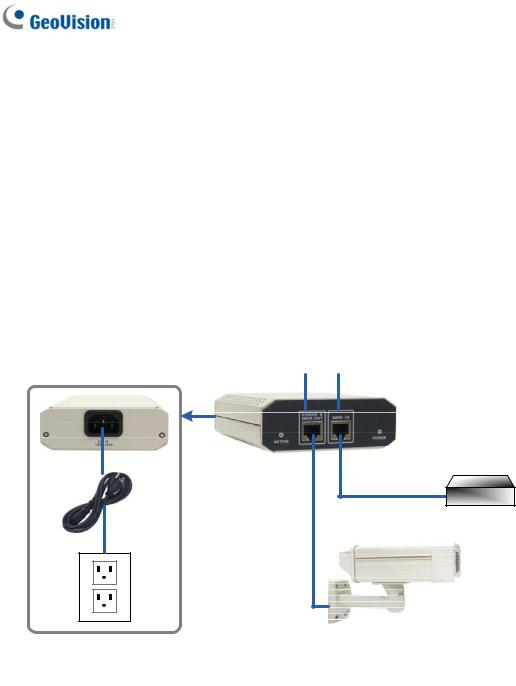
1.2.6Connecting the Camera
It is suggested to use GV-PA191 PoE Adapter to connect the GV-IP LPR Camera 5R to the network. Follow the steps below for connection.
1.Connect the camera’s cable to the GV-PA191 PoE Adapter as illustrated below. The power and network will be supplied simultaneously.
Rear Panel
LAN 10/100 Power IN |
|
|
(+) |
(-) |
GV-PA191 PoE Adapter |
|
||
Ethernet |
|
|
Cable |
|
PoE |
Power |
|
|
Hub/Router |
|
GV-IP LPR Camera 5R |
|
|
Figure 1-14
2.When the Power LED on the front panel of the GV-PA191 PoE Adapter turns green, you are ready to access the live view, adjust the image clarity and configure the basics. See Getting Started, Chapter 2.
Note: The GV-PA191 PoE Adapter (AC Power Adapter included) can be purchased upon request.
18

2 Getting Started
1.2.7Adjusting the Angles
The GV-IP LPR Camera 5R is designed to be adjustable in three shafts for easy and flexible installation.
First Shaft
You can adjust the camera body by 360 degrees to the right or the left. 1. Unscrew the panning lock screw with the torx wrench.
Panning Lock Screw
Figure 1-15
2. Adjust the angle of camera body to the right or the left, and fasten the panning lock screw.
0 ~ 360°
Figure 1-16
19

Second Shaft
You can adjust the camera body up and down by 90, 112.5, 135, 157.5 or 180 degrees by using the gears inside the camera body and the camera base.
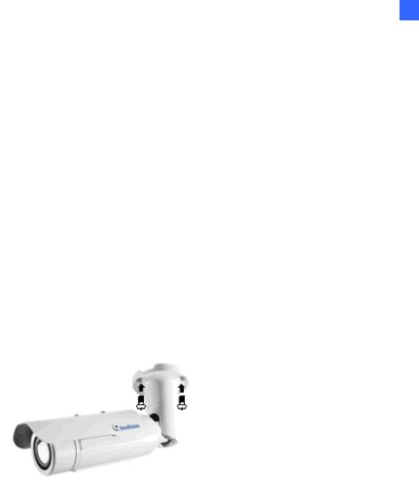
1. Unscrew the tilting lock screw with the torx wrench.
Tilting Lock Screw
Torx Wrench
Figure 1-17
2.Hold the camera body, and move the camera base to the right to separate the camera gears.
Move the Camera

 Base to the Right
Camera Gears
Camera Body
Figure 1-18
3.Adjust the angle of camera body to 90°, 112.5°, 135°, 157.5° or 180°. Then move the camera base to the left to combine the gears.
180°157.5° |
135° |
112.5° |
90° |
Figure 1-19
4. Fasten the tilting lock screw.
20
2 Getting Started
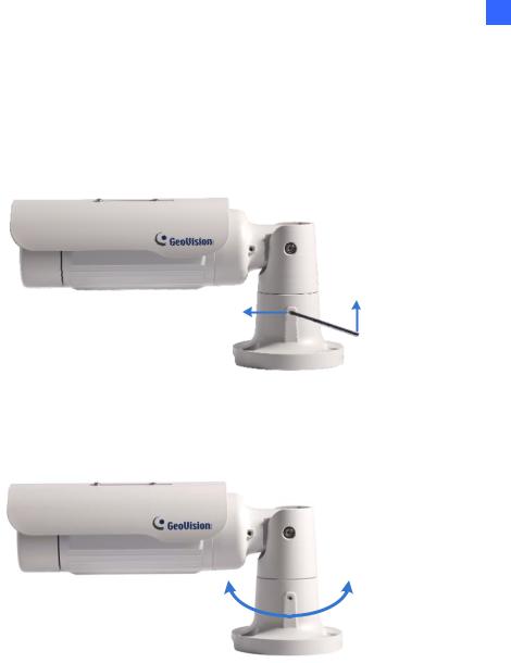
Third Shaft
You can adjust the camera base by 360°.
1. Unscrew the base fixing screw with the torx wrench.
Figure 1-20
2. Adjust the angle of camera base, and fasten the base fixing screw.
0~360°
Figure 1-21
21

1.2.8Replacing the Silica Gel Bag
To replace the original silica gel bag with a new one, follow the steps below.
1. Loosen the camera’s cover.
Camera’s Cover
Figure 1-22
2. Remove the silica gel bag.
Silica Gel Bag
Figure 1-23
3.Insert a new silica gel bag to the camera module and fasten the camera’s cover within 2 minutes of opening the silica gel bag package.
IMPORTANT:
1.The silica gel loses its effectiveness when the dry camera is opened. To prevent the lens from fogging up, replace the silica gel bag every time when you open the camera and conceal the gel bag in the camera within two minutes of exposing to the open air.
2.For each newly replaced silica gel bag, allow it to absorb moisture for at least 5 hours before operating the camera.
22
Loading...