


 Loading...
PN401, PN400, PN300 & SQP133
User’s Manual
PN-A

© 2020 GeoVision, Inc. All rights reserved.
Under the copyright laws, this manual may not be copied, in whole or in part, without the written consent of GeoVision.
Every effort has been made to ensure that the information in this manual is accurate. GeoVision, Inc. makes no expressed or implied warranty of any kind and assumes no responsibility for errors or omissions. No liability is assumed for incidental or consequential damages arising from the use of the information or products contained herein. Features and specifications are subject to change without notice.
Note: No memory card slot or local storage function for Argentina.
GeoVision, Inc.
9F, No. 246, Sec. 1, Neihu Rd., Neihu District, Taipei, Taiwan Tel: +886-2-8797-8377
Fax: +886-2-8797-8335 http://www.geovision.com.tw
Trademarks used in this manual: GeoVision, the GeoVision logo and GV series products are trademarks of GeoVision, Inc. Windows is the registered trademark of
Microsoft Corporation.
May 2020
Contents
Preface |
................................................................................................................................ |
|
|
vii |
Compatible .................................................................Firmware and Software Versions |
viii |
|||
Caution............................................................................................................................... |
|
|
|
viii |
Chapter .....................................................................................................1 |
Introduction |
1 |
||
1.1 ................................................................................ |
Features of PN400 and PN401 |
1 |
||
1.2 ............................................................................................................. |
Packing List |
1 |
||
...................................................................................................... |
|
1.2.1 |
PN401 |
1 |
...................................................................................................... |
|
1.2.2 |
PN400 |
2 |
...................................................................................................... |
|
1.2.3 |
PN300 |
2 |
.................................................................................................... |
|
1.2.4 |
SQP133 |
2 |
1.3 ................................................................................................................... |
Options |
|
3 |
|
1.4 ................................................................................................................. |
Overview |
|
4 |
|
...................................................................................................... |
|
1.4.1 |
PN401 |
4 |
...................................................................................................... |
|
1.4.2 |
PN400 |
6 |
...................................................................................................... |
|
1.4.3 |
PN300 |
8 |
................................................................................................... |
|
1.4.4 |
SQP133 |
10 |
1.5 ........................................................................................... |
The IR Remote Control |
12 |
||
Chapter ................................................................................................2 |
Getting Started |
14 |
||
2.1 ............................................................................................ |
Connecting the Device |
14 |
||
............................................................................. |
|
2.1.1 |
Connecting the PN401 |
14 |
............................................................................. |
|
2.1.2 |
Connecting the PN400 |
15 |
............................................................................. |
|
2.1.3 |
Connecting the PN300 |
16 |
.......................................................................... |
|
2.1.4 |
Connecting the SQP133 |
17 |
2.2 ............................................................................................... |
Installing Wall Mount |
18 |
||
2.3 ............................................................................... |
Installing VESA Monitor Mount |
19 |
||
2.4 ............................................................................................. |
Playing the Slideshow |
20 |
||
Chapter ................................................................3 System Setup for PN300 / SQP133 |
21 |
|||
3.1 ..................................................................................................... |
The Setup Menu |
21 |
||
3.2 ...................................................................... |
Setting Video Output and Resolution |
22 |
||
3.3 ............................................................................. |
Setting Slideshow Display Effect |
23 |
||
3.4 ............................................................................... |
Looking Up Device Information |
24 |
||
3.5 ..................................................................................................... |
Setting the Time |
25 |
||
.......................................................................... |
|
3.5.1 |
Setting the System Time |
25 |
.............................................................................. |
|
3.5.2 |
Setting the Time Zone |
25 |
3.6 ................................................................................................ |
Setting the Network |
26 |
||
...................................................................... |
|
3.6.1 |
Wired Network Connection |
26 |
iii
|
|
3.6.2 |
Wireless Network Connection.................................................................. |
27 |
3.7 |
Setting the Device Name ........................................................................................ |
28 |
||
3.8 |
Copying Files from the USB Storage Device .......................................................... |
28 |
||
3.9 |
Upgrading the Firmware ......................................................................................... |
29 |
||
3.10 Restoring to Factory Default Settings ................................................................... |
30 |
|||
Chapter 4 System Setup for PN400 / PN401................................................................... |
31 |
|||
4.1 |
The Setup Menu ..................................................................................................... |
31 |
||
4.2 |
Connectivity Status................................................................................................. |
33 |
||
4.3 |
Configuring the General Settings............................................................................ |
34 |
||
4.4 |
Upgrading the Firmware ......................................................................................... |
35 |
||
4.5 |
Setting the Network ................................................................................................ |
36 |
||
|
|
4.5.1 |
Wired Network Connection ...................................................................... |
36 |
|
|
4.5.2 |
Wireless Network Connection.................................................................. |
37 |
4.6 |
Setting the Time ..................................................................................................... |
38 |
||
4.7 |
Connecting to CMS ................................................................................................ |
39 |
||
4.8 |
Scheduling the Power On and Off........................................................................... |
39 |
||
Chapter 5 |
Content Designer............................................................................................ |
41 |
||
5.1 |
Minimum System Requirements ............................................................................. |
41 |
||
5.2 |
Installing the Content Designer............................................................................... |
42 |
||
5.3 |
The Menu Bar......................................................................................................... |
42 |
||
5.4 |
Creating a Project................................................................................................... |
43 |
||
|
|
5.4.1 Create a Screen Layout........................................................................... |
43 |
|
|
|
5.4.2 |
The Main Screen ..................................................................................... |
45 |
|
|
5.4.3 Assign Content to Zones.......................................................................... |
48 |
|
|
|
5.4.4 Preview and Save Screen Layout ............................................................ |
54 |
|
5.5 |
Playing the Project.................................................................................................. |
55 |
||
Chapter 6 |
Content Schedule ........................................................................................... |
57 |
||
6.1 |
Minimum System Requirements ............................................................................. |
57 |
||
6.2 |
Installing the Content Schedule .............................................................................. |
57 |
||
6.3 |
Setting the Content Schedule ................................................................................. |
58 |
||
Chapter 7 |
CMS Lite.......................................................................................................... |
63 |
||
7.1 |
Minimum System Requirements ............................................................................. |
64 |
||
7.2 |
Software License .................................................................................................... |
64 |
||
7.3 |
Installing the CMS Lite............................................................................................ |
65 |
||
7.4 |
Connecting the Devices to CMS Lite ...................................................................... |
66 |
||
7.5 |
The Main Screen .................................................................................................... |
67 |
||
7.6 |
Uploading Video and Image Files ........................................................................... |
69 |
||
7.7 |
Uploading the Scenario or Loop Scenario............................................................... |
70 |
||
iv
7.8 |
Uploading the Schedule.......................................................................................... |
71 |
|
7.9 |
Uploading the Firmware.......................................................................................... |
72 |
|
7.10 |
Uploading the Scrolling Ticker .............................................................................. |
73 |
|
7.11 Changing the Device Name.................................................................................. |
74 |
||
Chapter 8 CMS Server ..................................................................................................... |
75 |
||
8.1 |
System Requirements ............................................................................................ |
76 |
|
|
8.1.1 |
Minimum System Requirements .............................................................. |
76 |
|
8.1.2 |
Software License ..................................................................................... |
77 |
8.2 |
Installing CMS Server ............................................................................................. |
78 |
|
8.3 |
Connecting the Devices to CMS Server.................................................................. |
79 |
|
8.4 |
Starting CMS Server............................................................................................... |
80 |
|
|
8.4.1 List of Menu Options................................................................................ |
82 |
|
8.5 |
Getting Started ....................................................................................................... |
83 |
|
|
8.5.1 |
Preparing the Package ............................................................................ |
83 |
|
8.5.2 |
Transferring the Package......................................................................... |
84 |
|
8.5.3 |
Uploading the Package............................................................................ |
88 |
|
8.5.4 |
Revising the Package .............................................................................. |
90 |
8.6 |
Applying the Scrolling Ticker................................................................................... |
91 |
|
8.7 |
Applying the RSS Feed .......................................................................................... |
92 |
|
8.8 |
Planning Device Group........................................................................................... |
93 |
|
8.9 |
Arranging the Loop Video ....................................................................................... |
95 |
|
8.10 |
Information ........................................................................................................... |
96 |
|
|
8.10.1 |
Device Information................................................................................. |
96 |
|
8.10.2 |
System Information................................................................................ |
97 |
|
8.10.3 |
User Information .................................................................................... |
97 |
|
8.10.4 |
Package Information.............................................................................. |
98 |
8.11 |
Device Setup ........................................................................................................ |
98 |
|
8.12 |
Event Query ....................................................................................................... |
100 |
|
|
8.12.1 |
Behavior Log Query............................................................................. |
100 |
|
8.12.2 |
Behavior Log Analysis.......................................................................... |
101 |
|
8.12.3 |
Device Event Query............................................................................. |
102 |
|
8.12.4 |
Device Event Analysis (Counts) ........................................................... |
103 |
|
8.12.5 Device Event Analysis (Elapsed Time)................................................. |
104 |
|
|
8.12.6 |
Play Count Analysis ............................................................................. |
105 |
8.13 |
Upload Management .......................................................................................... |
107 |
|
8.14 |
Server Setting..................................................................................................... |
108 |
|
|
8.14.1 |
User Account ....................................................................................... |
108 |
|
8.14.2 |
Network Setting ................................................................................... |
109 |
v
|
8.14.3 |
Email Service....................................................................................... |
110 |
|
8.15 |
Upgrading the Firmware ..................................................................................... |
111 |
||
Chapter 9 |
Dynamic DNS................................................................................................ |
113 |
||
Chapter 10 |
DigitalSignageManagementServer.................................................................... |
114 |
||
10.1 |
System Requirements ........................................................................................ |
114 |
||
10.2 |
ConnectingPN401toDigitalSignageManagementServer................................................. |
114 |
||
10.3 |
Transferring the Package ................................................................................... |
118 |
||
10.4 |
Uploading the Package....................................................................................... |
119 |
||
|
10.4.1 Uploading and Scheduling Content Packages ..................................... |
119 |
||
|
10.4.2 |
Assigning Tickers................................................................................. |
120 |
|
10.5 |
Content Package Schedules and Statistics......................................................... |
121 |
||
|
10.5.1 Reviewing the Uploaded Content Packages ........................................ |
121 |
||
|
10.5.2 |
Viewing Reports................................................................................... |
122 |
|
10.6 |
Creating User Accounts...................................................................................... |
122 |
||
Specifications................................................................................................................... |
|
123 |
||
PN401........................................................................................................................... |
|
|
123 |
|
PN400........................................................................................................................... |
|
|
123 |
|
PN300........................................................................................................................... |
|
|
124 |
|
SQP133 ........................................................................................................................ |
|
|
125 |
|
Appendix........................................................................................................................... |
|
|
126 |
|
A. Definitions of Folder Names...................................................................................... |
126 |
|||
B. Definitions of Aspect Ratio Mode .............................................................................. |
127 |
|||
vi

Preface
Welcome to the PN401, PN400, PN300 & SQP133 User’s Manual.
The PN401, PN400, PN300 & SQP133 are devices that play back slideshows edited or managed by GeoVision’s software such as Content Designer, Content Schedule, CMS Lite, CMS Server, and Digital Signage Management Server. This Manual is designed for the following models and software.
Hardware
Model
PN401
PN400
PN300
SQP133
Software
Model
Content Designer
Content Schedule
CMS Lite
CMS Server
Digital Signage Management Server
vii
Compatible Firmware and Software Versions
|
|
|
|
PN401 |
|
PN400 |
|
|
PN300 / SQP133 |
|
SQP110 Series |
|
|
|
|
|
|
|
|
|
|
|
|
|
Digital Signage |
|
|
|
|
|
|
|
|
|
|
|
Management |
|
|
V1.00 |
|
|
N/A |
|
|
||
|
Server |
|
|
|
|
|
|
|
|
|
N/A |
|
CMS Server / CMS |
|
|
N/A |
|
V1.00 ~ V1.01 |
|
|
V1.06 |
|
|
|
Lite V1.0.5 |
|
|
|
|
|
|
|
|||
|
|
|
|
|
|
|
|
|
|
|
|
|
|
|
|
|
|
|
|
|
|
|
|
|
Content Designer |
|
|
V1.00 |
|
V1.00 ~ V1.01 |
|
|
V1.05 |
|
N/A |
|
V1.0.8 |
|
|
|
|
|
|
||||
|
|
|
|
|
|
|
|
|
|
|
|
|
|
|
|
|
|
|
|
|
|
|
|
|
Content Schedule |
|
|
V1.00 |
|
V1.00 ~ V1.01 |
|
|
V1.05 or later |
|
N/A |
|
V1.0.5 |
|
|
|
|
|
|
||||
|
|
|
|
|
|
|
|
|
|
|
|
|
|
|
|
|
|
|
|
|
|
|
|
Caution
PN400 and PN401 are designed only for indoor usage.
viii

1 Introduction
Chapter 1 Introduction
The PN400 and PN401 are digital media players designed to deliver uninterrupted playback of Digital Signage presentations.
1.1Features of PN400 and PN401
Multimedia support
Video resolution up to 4K2K
Support for HDMI
SD card and USB storage
Content Schedule and Content Designer
Content Management Server
DC 12V / PoE (IEEE 802.3af) (PoE for PN401 only)
IR remote control
USB mouse control
Wireless connectivity (PN400 only)
1.2Packing List
1.2.1 PN401
1.PN401 Device x 1
2.IR Remote Control x 1
3.Download Guide x 1
4.Warranty Card x 1
Note: Power adapters can be purchased upon request.
1

1.2.2 PN400
1.PN400 Device x 1
2.IR Remote Control x 1
3.AC/DC Adapter x 1 (12 V, 3 A, 36 W)
4.Power Cord x 1
5.Software DVD x 1
6.Warranty Card x 1
1.2.3 PN300
1.PN300 Device x 1
2.IR Remote Control x 1
3.AC/DC Adapter x 1 (12 V, 3 A, 36 W)
4.Power Cord x 1
5.Software DVD x 1
6.Warranty Card x 1
1.2.4 SQP133
1.SQP133 Device × 1
2.IR Remote Control × 1
3.Magnetic Hinge x 1
4.Screw x 4
5.AC/DC Adapter × 1 (12 V, 3 A, 36 W)
6.Power Cord x 1
7.Software DVD x 1
8.Warranty Card x 1
2
1 Introduction
1.3Options
Optional devices can expand the capabilities and versatility of your device. Contact our sales representatives for more information.
Options |
|
Details |
|
|
|
Wall Mount Kit |
|
The Wall Mount Kit is used to mount the PN400 / PN401 to |
|
|
|
|
|
the wall. |
|
|
|
|
|
L-type brackets x 2 |
|
|
Small screws x 4 |
|
|
|
VESA Monitor-Mount Kit |
|
The VESA Monitor Mount Kit is used to mount the PN400 / |
|
|
|
|
|
PN401 to the back of a VESA monitor. |
|
|
|
|
|
VESA monitor mount bracket x 1 |
|
|
L-type brackets x 2 |
|
|
Large screws x 4 |
|
|
Small screws x 8 |
|
|
|
Internal GV-USB Dongle |
|
The USB dongle can provide the Hardware Watchdog |
for CMS Lite and CMS |
|
function to the system by restarting the computer when |
Server |
|
Windows crashes. You need to connect the dongle internally |
|
|
on the motherboard. |
|
|
Note: This option is not supported by PN401. |
GV-WiFi Adapter V2 |
|
The GV-WiFi Adaptor V2 is a plug-and-play device that |
|
|
provides wireless connectivity to GeoVision IP devices. This |
|
|
product supports 2.4 GHz and 5 GHz wireless connection. |
|
|
Note: This option is not supported by PN401. For PN400, the |
|
|
mini USB converter is not supported. |
|
|
|
GV-PoE Adapter |
|
GV-PoE Adapter is designed to provide power to the IP |
|
|
device through a single Ethernet cable. Adopting the PoE |
|
|
adapter enables you to mount an IP device anywhere in a |
|
|
building where power outlets are not available. (PN401 only) |
Power Adapter |
|
For PN401, contact our sales representatives for the |
|
|
countries and areas supported. |
|
|
|
SD card |
|
The SD card is used for local storage and firmware upgrade. |
|
|
(Micro SD card for PN401) |
3

1.4Overview
This section identifies the components of the PN401, PN400, PN300 and SQP133.
1.4.1 PN401
Front View
1 |
2 |
3 |
4 |
5 |
Figure 1-1
No. |
Name |
Function |
|
1 |
Micro SD Card |
Connect to a Micro SD card for local storage of snapshots and |
|
Slot |
firmware upgrade. |
||
|
|||
|
|
|
|
2 |
LED Indicators |
The red LED indicates the power is supplied. |
|
The green LED indicates the system is ready for use. |
|||
|
|
||
|
|
|
|
3 |
IR sensor |
Receive signal from GV-IR Remote Control for controlling the user |
|
interface at the maximum operation distance of 7 m (22.97 ft). |
|||
|
|
||
|
|
|
|
|
|
Reset the device to the default factory settings. Use a pin to press the |
|
4 |
Default |
default button for about 10 seconds. The system will then reset and |
|
|
|
reboot itself shortly. |
|
|
|
|
|
5 |
USB 3.0 |
Connect to a USB mouse or USB storage device |
|
|
|
|
4
1 Introduction
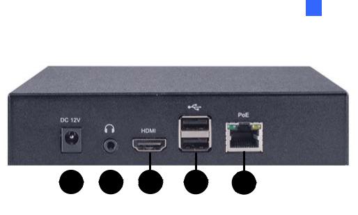
Rear View
|
|
|
|
|
3 |
4 |
|
|
|
|
|
|
|
||
|
1 |
2 |
5 |
||||
|
|
|
|
|
|
Figure 1-2 |
|
|
|
|
|
|
|
|
|
No. |
Name |
Function |
|
|
|
||
|
|
|
|
|
|||
1 |
DC 12V |
Connect to power by using a power adapter. |
|||||
|
|
|
|
|
|
||
2 |
Audio Out |
Connect to a speaker. |
|
||||
|
|
|
|
|
|||
3 |
HDMI |
Connect to an HDMI-compliant display device. |
|||||
|
|
|
|
|
|||
4 |
USB 2.0 |
Connect to a USB mouse or USB storage device. |
|||||
|
|
|
|
|
|||
5 |
Network / PoE |
Connect to the network or a GV-PoE Adapter. |
|||||
|
|
|
|
|
|
|
|
5
1.4.2 PN400
Front View
|
|
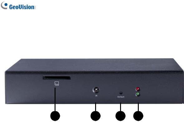
Figure 1-3 |
|
|
|
|
|
No. |
Name |
Function |
|
1 |
SD Card Slot |
Connect to an SD card for local storage and firmware upgrade. |
|
|
|
|
|
2 |
IR |
Built-in IR receiver to receive the IR signals from the IR remote |
|
control. |
|||
|
|
||
|
|
|
|
3 |
Default |
Reset the PN400 to the default factory settings. See 3.10 |
|
Restoring to Factory Default Settings for details. |
|||
|
|
||
|
|
|
|
|
|
The green LED indicates the system is ready. The red LED |
|
4 |
LED Indicators |
indicates the power is supplied. When the green LED is off and |
|
|
|
the red LED is on, the device is in sleep mode. |
|
|
|
|
6
1 Introduction
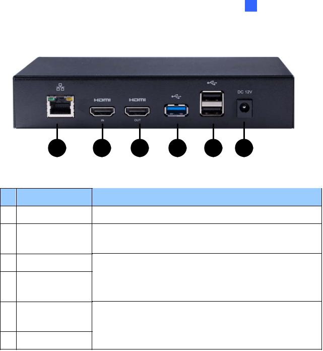
Rear View
No. Name
1Ethernet
2HDMI in
3HDMI out
4USB 3.0
5USB 2.0
6DC 12V
Figure 1-4
Function
Connect to an Ethernet.
Connect to a HDMI-compliant source device, such as a DVD player and digital TV box.
Connect to a HDMI-compliant display device.
Connect to a USB device for local storage of content, firmware upgrade and a USB mouse.
Connect to a USB device for local storage of content, firmware upgrade, a USB mouse, and GV-WiFi Adapter V2.
Connect to power by using the supplied power adapter.
7
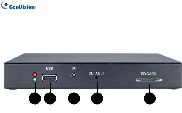
1.4.3 PN300
Front View
|
|
Figure 1-5 |
|
|
|
|
|
No. |
Name |
Function |
|
|
|
The green LED indicates the system is ready. The red LED |
|
1 |
LED Indicators |
indicates the power is supplied. When the green LED is off and |
|
|
|
the red LED is on, the device is in sleep mode. |
|
|
|
|
|
|
|
Connect to a USB device for local storage of content, firmware |
|
2 |
USB |
upgrade and GV-WiFi USB Adapter. Note the removal of the |
|
USB storage device will cause the PN300 to automatically |
|||
|
|
||
|
|
reboot. |
|
|
|
|
|
3 |
IR |
Built-in IR receiver to receive the IR signals from the IR remote |
|
control. |
|||
|
|
||
|
|
|
|
4 |
Default |
Reset the PN300 to the default factory settings. See 3.10 |
|
Restoring to Factory Default Settings. |
|||
|
|
||
|
|
|
|
|
|
Connect to an SD card for local storage and firmware upgrade. |
|
5 |
SD Card Slot |
Note the removal of the SD card will cause the PN300 to |
|
|
|
automatically reboot. |
|
|
|
|
8

1 Introduction
Rear View
|
|
Figure 1-6 |
|
|
|
No. |
Name |
Function |
|
|
|
1 |
Ethernet |
Connect to an Ethernet. |
|
|
|
2 |
SPDIF |
Reserved (not enabled). |
|
|
|
3 |
HDMI |
Connect to an HDMI supported display device. |
|
|
|
4 |
VGA |
Connect to a VGA monitor. |
|
|
|
5 |
L/R |
Connect to a speaker. |
|
|
|
6 |
Power OFF/ON |
Switch the power on or off. |
|
|
|
7 |
DC 12V |
Connect to power by using the supplied power adapter. |
|
|
|
9
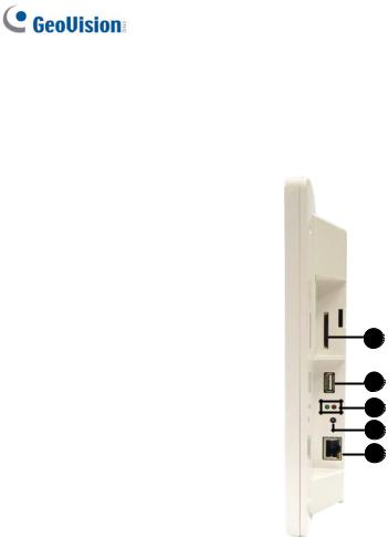
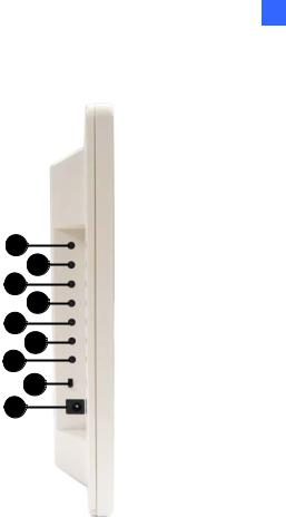
1.4.4 SQP133
Right Panel View
1
2
3
4
5
|
|
Figure 1-7 |
|
|
|
|
|
No. |
Name |
Function |
|
|
|
|
|
1 |
SD Card Slot |
Connect to an SD card for local storage of content and |
|
firmware upgrade. |
|||
|
|
||
|
|
|
|
|
|
Connect to a USB device for local storage of content, |
|
2 |
USB |
firmware upgrade, and GV-WiFi USB Adapter. Note the |
|
removal of the USB storage device will cause the SQP133 to |
|||
|
|
||
|
|
automatically reboot. |
|
|
|
|
|
|
|
The green LED indicates the system is ready. The red LED |
|
3 |
LED Indicators |
indicates the power is supplied. When the green LED is off |
|
|
|
and the red LED is on, the device is in sleep mode. |
|
|
|
|
|
4 |
IR |
Built-in IR receiver to receive the IR signals from the IR |
|
remote control. |
|||
|
|
||
|
|
|
|
5 |
Ethernet |
Connect to an Ethernet. |
|
|
|
|
10
1 Introduction
Left Panel
1
2
3
4
5
6
7
8
9
|
|
Figure 1-8 |
|
|
|
No. |
Name |
Function |
|
|
|
1. |
MENU |
Switch to the setup menu. |
|
|
|
2 |
ENTER |
Enter the setup options or save the settings in the Setup Menu. |
|
|
|
3 |
UP |
Move the cursor up. |
|
|
|
4 |
DOWN |
Move the cursor down. |
|
|
|
5 |
LEFT |
Move the cursor left. |
|
|
|
6 |
RIGHT |
Move the cursor right. |
|
|
|
|
|
Press to enter the Standby/Sleep mode. In the standby mode, the |
7 |
STAND BY |
screen turns off to minimize power consumption. Press the key |
|
|
again to enter the ON mode. |
|
|
|
8 |
Power OFF/ON |
Switch the power on or off. |
|
|
|
9 |
DC 12V |
Connect to power using the supplied power adapter. |
|
|
|
11

1.5The IR Remote Control
1
2 |
|
|
|
|
|
|
5 |
|
|
|
|
||||||
|
|
|
|
|
6 |
|
||
|
|
|
|
|
|
|||
|
|
|
|
|
|
|
||
3 |
|
|
7 |
|
||||
|
|
|||||||
4 |
|
|
|
8 |
|
|||
|
|
|
||||||
|
|
|
|
9 |
|
|||
|
|
|
|
10 |
||||
|
|
Figure 1-9 |
|
|
|
|
|
No. |
Name |
Function |
|
|
|
|
|
|
|
Press to enter the Standby/Sleep mode. In the standby mode, |
|
1 |
Power |
the screen turns off to minimize power consumption. Press the |
|
|
|
key again to enter the ON mode. |
|
|
|
|
|
|
Numeric / Alphabetical / |
|
|
2 |
Punctuation Marks |
Enter the numbers, alphabets or punctuation marks. |
|
|
Buttons |
|
|
|
|
|
|
3 |
Back |
Back to the previous page in the Setup Menu. |
|
Play the media files. |
|||
|
|
||
|
|
|
|
4 |
Menu Control |
Move up, down, right and left in the Setup Menu. |
|
|
|
|
|
5 |
Volume Control |
Increase or decrease the volume. |
|
|
|
|
|
6 |
Mute |
Mute the volume. |
|
|
|
|
|
7 |
Menu |
Switch to the setup menu. |
|
|
|
|
|
12 |
|
|
|
|
|
|
1 |
Introduction |
|
|
|
|
|
|
No. |
Name |
Function |
|
|
|
|
|
|
|
||
8 |
OK |
Enter the setup options or save the settings in the Setup Menu. |
|||
|
|
|
|||
|
|
Switch among different resolutions for PN300 / PN400 / |
|||
|
|
PN401. Once the button is pressed, the Green LED on the |
|||
|
|
front panel of the device will flash. Press No. 0 ~ 7 for the |
|||
|
|
desired resolution within 30 seconds. |
|||
|
|
For PN300: |
|
|
|
|
|
Shift + 0 : VGA_640 x 480 |
Shift + 4 : HDMI_480p |
||
|
|
Shift + 1 : VGA_1024 x 768 |
Shift + 5 : HDMI_720p |
||
|
|
Shift + 2 : VGA_1280 x 768 |
Shift + 6 : HDMI_1080i |
||
9 |
Shift |
Shift + 3 : VGA_1366 x 768 |
Shift + 7 : HDMI_1080p |
||
|
|
For PN400 / PN401: |
|
|
|
|
|
Shift + 1 : 1080p at 30 Hz |
|
|
|
|
|
Shift + 2 : 1080p at 60 Hz |
|
|
|
|
|
Shift + 3 : 2160p at 24 Hz |
|
|
|
|
|
Shift + 4 : 2160p at 30 Hz |
|
|
|
|
|
Note the resolution switch will cause the PN300 / PN400 / |
|||
|
|
PN401 to automatically reboot. |
|||
|
|
|
|||
10 |
Search |
Scan for available Access Points or wireless stations when |
|||
wireless network is selected. |
|
|
|
||
|
|
|
|
|
|
|
|
|
|
|
|
13
3 System Setup for PN300 / SQP133
Chapter 2 Getting Started
2.1Connecting the Device
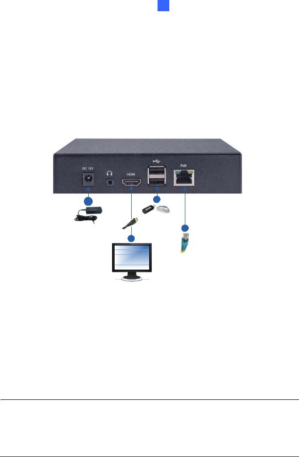
2.1.1 Connecting the PN401
Figure 2-1
1.Connect to a standard network cable for network or connect to a PoE adapter for power and network supplied together.
2.Connect to a USB mouse, and an USB device for local storage of content.
3.Connect a display device to HDMI connector for video and audio combined outputs.
4.Optionally connect to power using the purchased power adapter if PoE is not applied.
Note:
1.The default video output is set to 1080p at 60 Hz. To change the default setting, see 4.2 Configuring the General Settings.
2.Optional GV-PoE Adapter is required for applying PoE function.
14
2 Getting Started
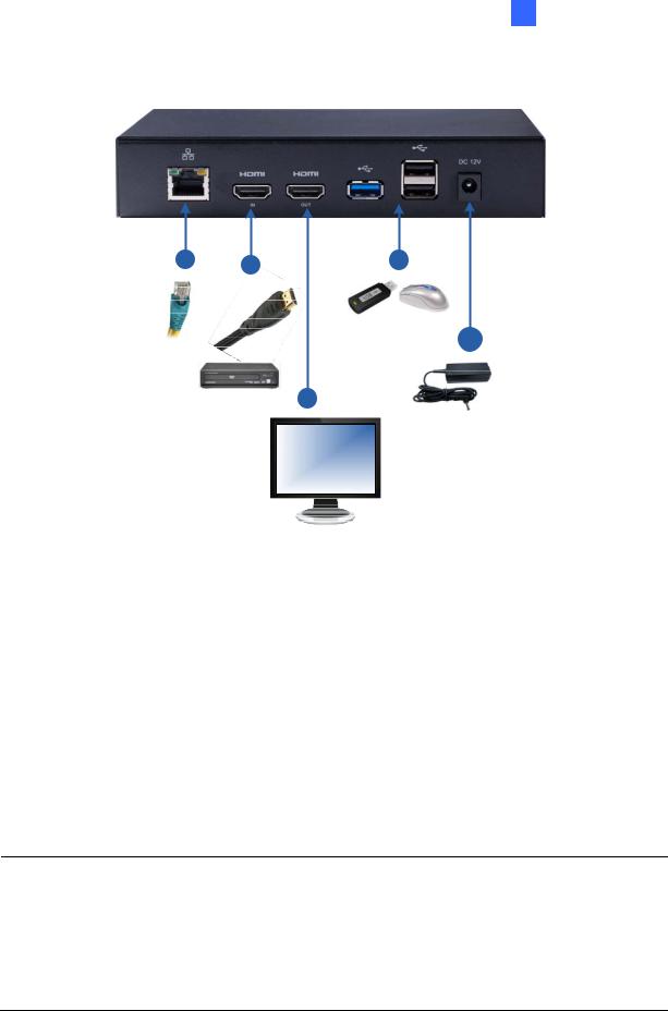
2.1.2 Connecting the PN400
Figure 2-2
1.Connect to a standard network cable.
2.Optionally, connect a HDMI-compliant source device, such as a DVD player and a digital TV box.
3.Connect a display device to HDMI connector for video and audio combined outputs.
4.Connect to a USB mouse, an USB device for local storage of content or firmware upgrade, or GV-WiFi Adapter V2 (for USB 2.0 port).
5.Connect to power using the supplied power adapter.
Note:
1.The default video output is set to 1080p at 30 Hz. To change the default setting, see 4.2 Configuring the General Settings.
2.The HDMI input (for HDMI-compliant source devices) only supports the resolution of up to 1920 x 1080 at 30 Hz.
15
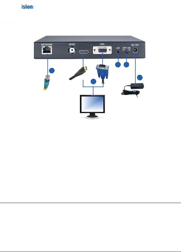
2.1.3 Connecting the PN300
3 5
2
4
1
Figure 2-3
1.Connect a monitor to the VGA connector, or the HDMI connector for video and audio combined outputs.
2.Connect to a standard network cable.
3.If you use a VGA monitor, connect a speaker to L/R port for audio output.
4.Connect to power using the supplied power adapter.
5.Switch the Power button to ON.
Note:
1.You can only connect the PN300 / SQP133 to one display device through the HDMI or VGA connector. The video signal will be unstable if more than one display devices are connected.
2.The default video resolution is set to VGA with 1024 x 768. To change the default setting, see 3.2 Setting Video Output and Resolution.
16
2 Getting Started
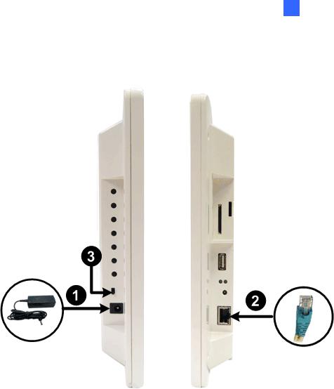
2.1.4 Connecting the SQP133
Follow the steps below to connect the SQP133:
Figure 2-4
1.Connect to power using the supplied power adapter.
2.Connect to a standard network cable.
3.Turn the Power switch to ON.
17
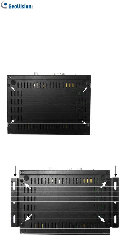
2.2Installing Wall Mount
Optionally, you can purchase the mounting plates to mount PN300, PN400, or PN401 on a wall.
1. Unscrew the 4 screws on the back panel of the device.
Figure 2-5
2. Use the 4 screws in the package to tighten the L-type brackets on the device.
L-Type Bracket |
L-Type Bracket |
Figure 2-6
18
2 Getting Started
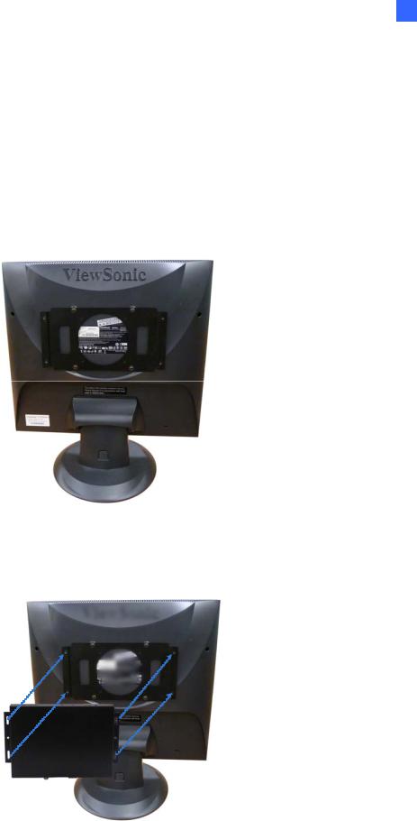
2.3Installing VESA Monitor Mount
Optionally, you can purchase VESA Monitor mount for installing PN300, PN400, or PN401.
1.Follow steps 1 and 2 in 2.2 Installing Wall Mount to tighten the L-type brackets on the back panel of the device.
2.Using the 4 large screws, tighten the VESA monitor mount bracket on the back of the computer monitor.
Figure 2-7
3.Use the 4 small screws to tighten the device and the VESA monitor mount bracket together.
Figure 2-8
19

2.4Playing the Slideshow
Without any further settings, you can now play the slideshow made of video or image files.
1.Create a folder named Loop_Video in a USB storage device or an SD card.
2.Copy image or video files to the Loop_Video folder.
3.Connect the USB storage device or the SD card to the device.
4.Turn on the digital signage device.
5.For PN300 / SQP133:
The local storage is set to the SD card by default. If you are using an SD card, the device will repeatedly play the files at this step.
If you are using a USB storage device, select Play Source  and select USB to be the storage.
6.For PN400 / PN401:
The local storage is disabled by default. To select a storage device, select General  and select SD or USB.
7.Press Back on the IR remote control to return the menu, and press Back again to start playing.
Note:
1.For the folder names workable on the device, see Definitions of Folder Names,
Appendix.
2.By default, the image and video files are sorted by name, first in numerical and then alphabetical order. Only for PN300 / SQP133, you can change the sorting rule to by size or by random; see the Loop Mode option, 3.3 Setting Slideshow Display Effect.
20
3 System Setup for PN300 / SQP133
Chapter 3 System Setup for PN300 / SQP133
You can customize the system settings of the PN300 / SQP133.
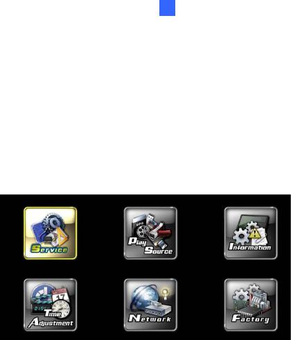
3.1The Setup Menu
Turn on the PN300 / SQP133 and the connected display device. The setup menu with six setup options appears.
Figure 3-1
|
Name |
|
Description |
|
|
|
|
|
Service |
|
Set up the video output and resolution. See 3.2 Setting Video Output |
|
|
and Resolution. |
|
|
|
|
|
|
|
|
|
|
Play Source |
|
Select the local storage and set up the slideshow display effect. See 3.3 |
|
|
Setting Slideshow Display Effect. |
|
|
|
|
|
|
|
|
|
|
Information |
|
Display the network information, storage information and the device |
|
|
firmware version. See 3.4 Looking Up Device Information. |
|
|
|
|
|
|
|
|
|
|
Time Adjustment |
|
Set up the system time. See 3.5 Setting the System Time. |
|
|
|
|
|
Network |
|
Set up the network. See 3.6 Setting the Network. |
|
|
|
|
|
|
|
Upgrade firmware or to copy files from the USB storage device to the SD |
|
Factory |
|
card. Select Language and Time Zone settings. See 3.5.2 Setting the |
|
|
Time Zone, 3.8 Copying Files from the USB Storage Device and 3.9 |
|
|
|
|
|
|
|
|
Upgrading the Firmware. |
|
|
|
|
21
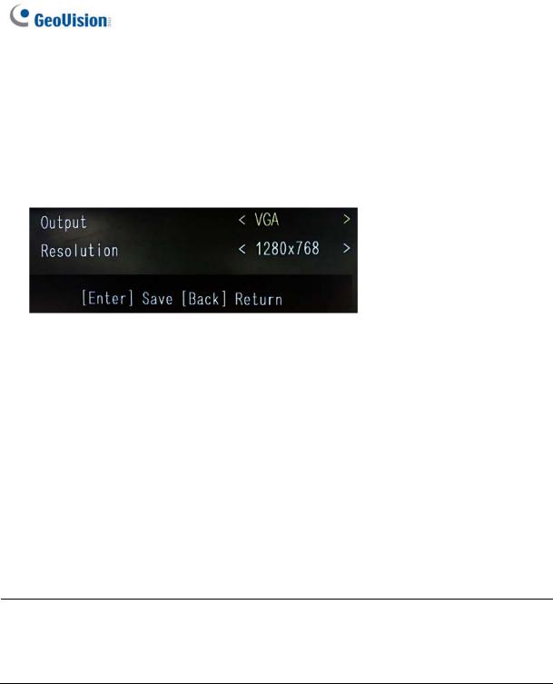
3.2Setting Video Output and Resolution
To set up the video output and resolution for PN300, select Service  . The following window appears.
Figure 3-2
Output: Select a video output from VGA or HDMI which is supported by the display monitor.
Resolution: Select a screen resolution from the following options:
HDMI at 60 Hz |
480p |
720p |
1080i |
1080p |
|
|
|
|
|
VGA at 60 Hz |
640 x 480 |
1024 x 768 |
1280 x 768 |
1366 x 768 |
|
|
|
|
|
By default, the video output is set to VGA with the resolution of 1024 x 768.
Note:
1.The video output and resolution for SQP133 cannot be changed.
2.The resolution change will cause the PN300 to automatically reboot.
22
Loading...