


 Loading...
GE Digital Energy
Power Quality
SGT5000_100-150_UPS_GE01


Operating Manual
Uninterruptible Power supply
Digital Energy™
SG Series
100 – 120 – 150 kVA
480 VAC UL / Series 0
Manufactured by:
GE Consumer & Industrial SA
General Electric Company
CH – 6595 Riazzino (Locarno)
Switzerland
T +41 (0)91 / 850 51 51
F +41 (0)91 / 850 51 44
www.gedigitalenergy.com
GE imagination at work
Model: |
SG Series 100 – 120 - 150 kVA / Series 0 |
Issue by |
Product Document Department – Riazzino - CH |
Date of issue: |
11/12/2008 |
File name: |
OPM_SGS_USM_M10_M15_0US_V030 |
Revision: |
3.0 |
Identification No.: |
|
Up-dating |
|
|
Revision |
Concerns |
Date |
2.0 |
House-style GE Consumer & Industrial |
01/30/2006 |
3.0 |
GE Digital Energy – Power Quality |
11/12/2008 |
|
|
|
COPYRIGHT © 2008 by GE Consumer & Industrial SA
All rights reserved.
The information contained in this publication is intended solely for the purposes indicated.
The present publication and any other documentation supplied with the UPS system is not to be reproduced, either in part or in its entirety, without the prior written consent of GE.
The illustrations and plans describing the equipment are intended as general reference only and are not necessarily complete in every detail.
The content of this publication may be subject to modification without prior notice.
Modifications reserved |
Page 2/82 |
OPM_SGS_USM_M10_M15_0US_V030.doc |
Operating Manual SG Series 100 – 120 - 150 kVA |

Dear Customer,
We thank you for selecting our products and are pleased to count you amongst our very valued customers at GE.
We trust that the use of the SG Series Uninterruptible Power Supply system, developed and produced to the highest standards of quality, will give you complete satisfaction.
Please read carefully the Operating Manual, which contains all the necessary information and describes all you need to know about the use of the UPS.
Thank you for choosing GE !
START UP AND COMMISSIONING
A GE Global Services Field Engineer must perform start-up and commissioning of the UPS. Please Contact GE. Global Services at least two weeks prior to schedule start-up and commissioning at 1-800-637-1738, or by E-mail at pqservices@ge.com
|
|
Distributed in the USA by: |
|
Your service contact: |
|
g |
|
|
g |
|
|
|
GE Digital Energy |
|
|
||
|
|
|
|
||
GE Consumer & Industrial SA |
|
|
Power Quality |
|
|
|
2501 Pecan Street |
|
|
||
General Electric Company |
|
|
|
||
|
Bonham, TX 75418 |
|
|
||
CH – 6595 Riazzino (Locarno) |
|
|
|
||
|
T: |
+1 800-637-1738 |
|
|
|
Switzerland |
|
|
|
||
|
F: |
+1 903-640-0533 |
|
|
|
www.gedigitalenergy.com |
|
|
|
||
|
E: GEPQSales@ge.com |
|
|
||
|
|
|
|
||
|
|
http://www.gedigitalenergy.com/ups |
|
|
|
|
|
|
|
|
|
Modifications reserved |
Page 3/82 |
OPM_SGS_USM_M10_M15_0US_V030.doc |
Operating Manual SG Series 100 – 120 - 150 kVA |

Preface
Congratulations on your choice of a SG Series Uninterruptible Power Supply (UPS). It will help eliminate Load disturbances due to unexpected power problems.
This Manual describes the function of the UPS module, the purpose and location of the switches, the meaning of the system events related to the front panel indication, and provides procedures for starting and stopping the equipment.
Please refer to the accompanying Installations Guide, which describes how to prepare the installation site, and it provides weight, dimensions and procedures for moving, installing and connecting the UPS.
While every care has been taken to ensure the completeness and accuracy of this manual, GE assumes no responsibility or liability for any losses or damages resulting from the use of the information contained in this document.
NOTE !
SG Series 100 – 120 - 150 kVA is a product that needs to be installed by a licensed and knowledgeable contractor.
We recommend that this manual be kept next to the UPS for future references.
If any problems are encountered with the procedures contained in this manual, please contact your Service Center before you proceed.
This document shall not be copied or reproduced without the permission of GE.
Some of the information contained in this manual may be changed without notice to reflect technical improvements.
Safety instructions
Read the safety instructions contained on the following pages carefully before the installation of the UPS, options and Battery System.
Pay attention to the rectangular boxes included in the text:
They contain important information and warning concerning electrical connections and personnel safety.
Parallel version secured with RPA
When included in the text, this symbol refers to operation needed only for parallel system.
Modifications reserved |
Page 4/82 |
OPM_SGS_USM_M10_M15_0US_V030.doc |
Operating Manual SG Series 100 – 120 - 150 kVA |
Table of contents
Page
1 |
IMPORTANT SAFETY INSTRUCTIONS ........................................................................................................ |
7 |
||
2 |
INTRODUCTION.......................................................................................................................................... |
10 |
||
3 |
DESCRIPTION.............................................................................................................................................. |
11 |
||
|
3.1 |
BLOCK DIAGRAM AND MAIN ELEMENTS .............................................................................................................................. |
11 |
|
|
3.2 |
OPERATION MODES....................................................................................................................................................................... |
12 |
|
|
|
3.2.1 |
Normal operation mode ................................................................................................................................................................... |
12 |
|
|
3.2.2 |
Utility failure operation ..................................................................................................................................................................... |
12 |
|
|
3.2.3 |
Utility recovery operation................................................................................................................................................................ |
13 |
|
|
3.2.4 |
Automatic Bypass ............................................................................................................................................................................... |
13 |
|
|
3.2.5 |
Manual Bypass ..................................................................................................................................................................................... |
13 |
|
3.3 |
PARALLEL SYSTEM OPERATION................................................................................................................................................ |
14 |
|
|
|
3.3.1 Introduction to the parallel system ............................................................................................................................................. |
14 |
|
|
|
3.3.2 Features of RPA parallel system ................................................................................................................................................... |
15 |
|
|
|
3.3.3 |
System control...................................................................................................................................................................................... |
15 |
|
|
3.3.4 |
Synchronization.................................................................................................................................................................................... |
15 |
|
|
3.3.5 |
Load sharing .......................................................................................................................................................................................... |
15 |
|
3.4 |
RECTIFIERS PARALLELED ON THE SAME BATTERY........................................................................................................... |
16 |
|
|
3.5 |
RECYCLING AT THE END OF SERVICE LIFE........................................................................................................................... |
17 |
|
4 |
LAYOUT........................................................................................................................................................ |
|
18 |
|
|
4.1 |
LAYOUT SG Series 100 - 120 - 150 kVA................................................................................................................................. |
18 |
|
5 |
CONTROL PANEL........................................................................................................................................ |
19 |
||
|
5.1 |
CONTROL PANEL............................................................................................................................................................................. |
19 |
|
|
5.2 |
TABLE OF FUNCTIONS AND INDICATIONS ON CONTROL PANEL.............................................................................. |
19 |
|
6 |
LCD SCREEN................................................................................................................................................ |
21 |
||
|
6.1 |
METERING MODE ............................................................................................................................................................................ |
22 |
|
|
6.2 |
ALARMS............................................................................................................................................................................................... |
25 |
|
|
6.3 |
PARAMETERS .................................................................................................................................................................................... |
26 |
|
|
6.4 |
EDIT MODE......................................................................................................................................................................................... |
28 |
|
|
6.5 |
USER PARAMETERS........................................................................................................................................................................ |
31 |
|
|
6.6 |
EVENTS (ALARMS AND MESSAGES)......................................................................................................................................... |
34 |
|
|
|
6.6.1 |
Alarms list................................................................................................................................................................................................ |
34 |
|
|
6.6.2 |
Messages list.......................................................................................................................................................................................... |
38 |
|
|
6.6.3 Event report SG Series........................................................................................................................................................................ |
40 |
|
7 |
OPERATION |
................................................................................................................................................. |
41 |
|
|
7.1 |
PROCEDURES FOR SINGLE UPS................................................................................................................................................ |
42 |
|
|
|
7.1.1 Start-up of the SG Series................................................................................................................................................................... |
42 |
|
|
|
7.1.2 Maintenance shutdown (Load on Q2)......................................................................................................................................... |
43 |
|
|
|
7.1.3 From Manual Bypass (Q2) to normal function VFI ................................................................................................................ |
44 |
|
|
|
7.1.4 Complete UPS shutdown (No Load supply).............................................................................................................................. |
45 |
|
|
|
7.1.5 Restore to normal operation after “total off”........................................................................................................................... |
46 |
|
|
|
7.1.6 Restore to normal operation after EPO (Emergency Power Off)...................................................................................... |
47 |
|
Modifications reserved |
Page 5/82 |
OPM_SGS_USM_M10_M15_0US_V030.doc |
Operating Manual SG Series 100 – 120 - 150 kVA |
7.2 PROCEDURES FOR UPS FUNCTIONING AS FREQUENCY CONVERTER .................................................................... |
48 |
|
7.2.1 Start-up of the SG Series as frequency converter................................................................................................................. |
48 |
|
7.2.2 Complete UPS shutdown (No Load supply).............................................................................................................................. |
49 |
|
7.2.3 |
Restore to normal operation after “total off”........................................................................................................................... |
50 |
7.2.4 |
Restore to normal operation after EPO (Emergency Power Off)...................................................................................... |
51 |
7.3 |
PROCEDURES FOR PARALLEL SYSTEM.................................................................................................................................. |
52 |
|
7.3.1 Parallel System start-up ................................................................................................................................................................... |
52 |
|
7.3.2 Maintenance system shutdown (Load supplied from Q2 on all Units)........................................................................ |
54 |
|
7.3.3 From Manual Bypass (Q2) to normal function VFI ................................................................................................................ |
55 |
|
7.3.4 Separate a Unit from the parallel system (System Redundancy).................................................................................. |
57 |
|
7.3.5 Reconnect a Unit to a parallel system ....................................................................................................................................... |
58 |
|
7.3.6 Parallel system shutdown (No Load supply) ........................................................................................................................... |
59 |
|
7.3.7 Restore to normal operation after “total off”........................................................................................................................... |
61 |
|
7.3.8 Restore to normal operation after EPO (Emergency Power Off)...................................................................................... |
63 |
7.4 |
PROCEDURES FOR PARALLEL SYSTEM WITH COMMON BATTERY............................................................................ |
65 |
|
7.4.1 Parallel System start-up ................................................................................................................................................................... |
65 |
|
7.4.2 Maintenance system shutdown (Load supplied from Q2 on all Units)........................................................................ |
67 |
|
7.4.3 From Manual Bypass (Q2) to normal function VFI ................................................................................................................ |
68 |
|
7.4.4 Separate a Unit from the parallel system (System Redundancy).................................................................................. |
70 |
|
7.4.5 Reconnect a Unit to a parallel system ....................................................................................................................................... |
71 |
|
7.4.6 Parallel system shutdown (No Load supply) ........................................................................................................................... |
72 |
|
7.4.7 Restore to normal operation after “total off”........................................................................................................................... |
74 |
|
7.4.8 Restore to normal operation after EPO (Emergency Power Off)...................................................................................... |
76 |
8 |
OPTIONS...................................................................................................................................................... |
78 |
|
|
8.1 |
COMMUNICATION OPTIONS ...................................................................................................................................................... |
78 |
|
8.2 |
OPTIONS IN UPS CABINET........................................................................................................................................................... |
78 |
|
8.3 |
CONNECTION FOR OPTIONS...................................................................................................................................................... |
79 |
|
|
8.3.1 Remote Signalling Box (RSB) ........................................................................................................................................................... |
79 |
9 |
MAINTENANCE ........................................................................................................................................... |
80 |
|
|
9.1 MAINTENANCE................................................................................................................................................................................. |
80 |
|
|
9.1.1 |
Service check ......................................................................................................................................................................................... |
80 |
|
9.1.2 |
Fans and ventilation ........................................................................................................................................................................... |
80 |
|
9.1.3 Other components with limited lifetime .................................................................................................................................... |
80 |
|
|
9.1.4 |
Battery...................................................................................................................................................................................................... |
80 |
|
9.1.5 Long shut-down periods of the UPS-system .......................................................................................................................... |
81 |
|
|
9.1.6 UPS room conditions and temperature..................................................................................................................................... |
81 |
|
|
9.1.7 Long shut-down periods of the UPS-system .......................................................................................................................... |
81 |
|
10 NOTES .......................................................................................................................................................... |
82 |
10.1 NOTES FORM .................................................................................................................................................................................... |
82 |
Modifications reserved |
Page 6/82 |
OPM_SGS_USM_M10_M15_0US_V030.doc |
Operating Manual SG Series 100 – 120 - 150 kVA |

1 IMPORTANT SAFETY INSTRUCTIONS
SAVE THESE INSTRUCTIONS
This manual contains important instructions for models SG Series 100 - 120 - 150 kVA that should be followed during installation and maintenance of the UPS and battery.
GENERAL
-Move the UPS in an upright position in its original package to the final destination room. To lift the cabinets, use a forklift or lifting belts with spreader bars.
-Check for sufficient floor and elevator loading capacity.
-Check the integrity of the UPS equipment carefully.
If you notice visible damage, do not install or start the UPS. Contact the nearest Service Center immediately.
-WARNING! RISK OF ELECTRICAL SHOCK:
Do not remove covers, there are no user serviceable parts inside.
-After switching off takes 5 minutes for the DC capacitors to discharge because a lethally high voltage remains at the terminals of the electrolytic capacitors.
-All maintenance and service work should be performed by qualified service personnel. The UPS contains its own energy source (battery).
-The field-wiring outlets may be electrically live, even when the UPS is disconnected from the utility.
-Dangerous voltages may be present during battery operation.
-The battery must be disconnected during maintenance or service work.
-This UPS contains potentially hazardous voltages.
-Be aware that the inverter can restart automatically after the utility voltage is restored.
INSTALLATION
-This UPS must be installed and connected only by trained personnel.
-Verify accurately during Commissioning and Maintenance of the UPS, for the following: Damaged components, squeezed wires and cables, or not correctly inserted plugs.
-After removing the sidewalls of the UPS, make sure that all earth connections when reassembling, are correctly reattached.
-This UPS is intended for use in a controlled indoor environment free of conductive contaminants and protected against animals intrusion.
-WARNING! HIGH EARTH LEAKAGE CURRENT:
Earth connection is essential before connecting to AC input!
-Switching OFF the unit does not isolate the UPS from the utility.
-Do not install the UPS in an excessively humid environment or near water.
-Avoid spilling liquids on or dropping any foreign object into the UPS.
-The unit must be placed in a sufficiently ventilated area; the ambient temperature should not exceed 95°F (35°C).
-Optimal battery life is obtained if the ambient temperature does not exceed 77°F (25°C).
-It is important that air can move freely around and through the unit. Do not block the air vents.
-Avoid locations in direct sunlight or near heat sources.
STORAGE
-Store the UPS in a dry location; storage temperature must be within -13°F (-25°C) to 131°F (+55°C).
-If the unit is stored for a period exceeding 3 months, the battery must be recharged periodically (time depending on storage temperature).
BATTERY
-The battery-voltage is dangerous for person’s safety.
-When replacing the battery, use the same cells number, voltage (V), capacity (Ah). All the battery used, shall be of the same manufacturer and date of production.
-Proper disposal or recycling of the battery is required. Refer to your local codes for disposal requirements.
-Never dispose of battery in a fire: they may explode.
-Do not open or mutilate battery: their contents (electrolyte) may be extremely toxic. If exposed to electrolyte, wash immediately with plenty of water.
-Avoid charging in a sealed container.
-Never short-circuit the batteries.
When working with batteries, remove watches, rings or other metal objects, and only use insulated tools.
-In case of air shipment, the cables +/- going to the battery fuses/terminals shall be disconnected and isolated.
Modifications reserved |
Page 7/82 |
OPM_SGS_USM_M10_M15_0US_V030.doc |
Operating Manual SG Series 100 – 120 - 150 kVA |

Safety instructions when working with battery
EXTERNAL BATTERY MUST BE INSTALLED AND CONNECTED TO THE UPS BY QUALIFIED SERVICE PERSONNEL.
INSTALLATION PERSONNEL MUST READ THIS ENTIRE SECTION BEFORE HANDLING THE UPS AND BATTERY.
DANGER!
Full voltage and current are always present at the battery terminals.
The battery used in this system can provide dangerous voltages, extremely high currents and a risk of electric shock.
If the terminals are shorted together or to ground they may cause severe injury.
You must be extremely careful to avoid electric shock and burns caused by contacting battery terminals or shorting terminals during battery installation.
Do not touch uninsulated battery terminals.
A qualified service person, who is familiar with battery systems and required precautions, must install and service the battery.
The installation must conform to national and local codes. Keep unauthorised personnel away from the battery.
The qualified service person must take these precautions:
1Wear protective clothing, such as rubber gloves and boots and protective eye wear Batteries contain caustic acids and toxic materials and can rupture or leak if mistreated. Remove rings and metal wristwatches or other metal objects and jewelry.
Do not carry metal objects in your pockets where the objects can fall into the battery cabinet.
2Tools must have insulated handles and must be insulated so that they will not short battery terminals.
Do not allow a tool to short between individual or separate battery terminals or to the cabinet or rack.
Do not lay tools or metal parts on top of the battery, and do not lay them where they could fall onto the battery or into the cabinet.
3Install the battery as shown on the drawing provided with the battery.
When connecting cables, never allow a cable to short across a battery’s terminals, the string of battery, or to the cabinet or rack.
4Align the cables on the battery terminals so that the cable lug will not contact any part of the cabinet or rack, even if the battery is moved.
Keep the cable away from any sharp metal edges.
5Install the battery cables in such a way that the UPS or battery cabinet doors cannot pinch them.
6Do not connect the battery terminal to Ground.
If any battery terminal is inadvertently grounded, remove the source of the ground. Contacting any part of a grounded battery can cause a risk of electric shock.
7To reduce the risk of fire or electric shock, install the battery in a temperature and humidity controlled indoor area, free of contaminants.
8Battery system chassis ground (earth) must be connected to the UPS chassis ground (earth). If you use conduits, this ground conductor must be routed in the same conduit as the battery conductors.
9Where conductors may be exposed to physical damage, protect the conductors in accordance with all applicable codes.
10If you are replacing the battery or repairing battery connections, shut OFF the UPS and remove the battery fuses.
Modifications reserved |
Page 8/82 |
OPM_SGS_USM_M10_M15_0US_V030.doc |
Operating Manual SG Series 100 – 120 - 150 kVA |
Safety symbols and warnings
Safety warnings
The text of this manual contains some warnings to avoid risk to the persons and to avoid damages to the UPS system and the supplied critical loads.
The non-observance of the warnings reminding hazardous situations could result in human injury and equipment damages.
Please pay attention to the meaning of the following warnings and symbols.
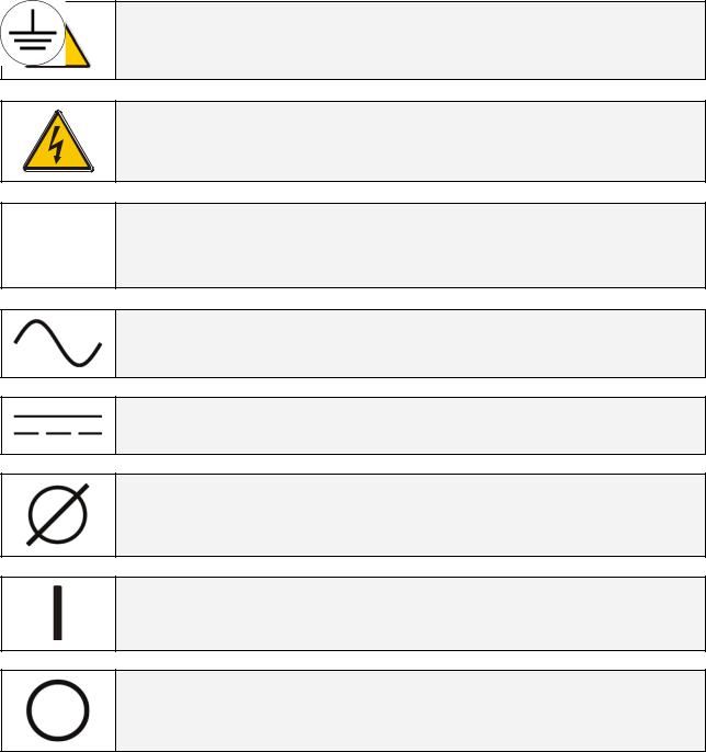
Throughout this manual the following symbols are defined:
WARNING, if instruction is not followed injury or serious equipment damage may occur!
CAUTION, internal parts have dangerous voltage present.
Risk of electric shock!
PE (Earth) – GND (Ground) PROTECTIVE GROUNDING TERMINAL:
A terminal which must be connected to earth ground prior to making any other connection to the equipment.
A terminal to which or from which an alternating (sine wave) current or voltage may be applied or supplied.
A terminal to which or from which a direct current or voltage may be applied or supplied.
This symbol indicated the word “phase”.
This symbol indicates the principal on/off switch in the on position.
This symbol indicates the principal on/off switch in the off position.
Modifications reserved |
Page 9/82 |
OPM_SGS_USM_M10_M15_0US_V030.doc |
Operating Manual SG Series 100 – 120 - 150 kVA |
2 INTRODUCTION
An Uninterruptible Power Supply (UPS) provides the power for critical loads that need a reliable, continuous, disturbance free supply.
In case the power provided by the Utility Fails, or exceeds the permitted tolerances, the power to supply the Load is provided by the Battery for the specified time at the rated Load (or longer at a reduced Load) or until the Utility power returns.
SG Series is a true double conversion VFI (Voltage Frequency Independent) UPS system where the Load is continuously supplied by the Inverter through the Rectifier.
In case of trouble on the Inverter Output Voltage, or when overload or short-circuit on the output occur, the Load is instantly transferred to the Utility via the Automatic Bypass.
The UPS automatically returns to normal mode when the failure condition is restored.
Key features:
•More Critical equipment supported
Rated at 0.8 Power Factor, SG Series delivers more real power than other UPS in the market.
With today’s trend toward power factor corrected loads, SG Series can support more total Load than any other UPS available, allowing you to support a greater number of today’s enterprise computing Power Factor Corrected (PFC) equipment.
•No single point of failure
Redundant Parallel Architecture (RPA) is an exclusive GE technology.
With RPA, SG Series UPS are controlled in a true peer-to-peer configuration where all critical elements and functions (including Bypass) are redundant.
SG Series is designed to be the most reliable power protection system available on the market today.
•High Efficiency
Using IGBT technology and Space Vector Modulation (SVM) strategy, SG Series offers low output voltage distortion and provides efficiencies up to 93%.
•Fully digital
Digital Signal Processor (DSP), Flash memory and SVM strategy, are the technology corner stones of new age of power quality and power reliability.
•Extremely flexible
Tailor made power protection to meet your individual installation requirements; SG Series offers various options like input harmonic filters and our comprehensive JUMP software suite for mission control and data protection to cover all your application needs.
Modifications reserved |
Page 10/82 |
OPM_SGS_USM_M10_M15_0US_V030.doc |
Operating Manual SG Series 100 – 120 - 150 kVA |
3 DESCRIPTION
3.1BLOCK DIAGRAM AND MAIN ELEMENTS
|
Fig. 3.1-1 Block diagram |
The SG Series system can be divided into the following main elements: |
|
Control System |
SG Series is designed with microprocessor-controlled signal processing |
circuits. The interface between the operator and the unit is provided by the monitoring system on the front panel.
This monitoring system consists of an active mimic diagram, a keyboard and a backlit display.
Rectifier The standard Rectifier consists of a 6-pulse SCR-bridge, which converts the 3- phase Utility Voltage into a controlled and regulated DC-voltage.
This regulated DC-voltage is used to supply power to the Inverter, and to provide charging power to the
Battery.
Inverter The Inverter converts the DC voltage into a three-phase AC-voltage with constant amplitude and frequency, which is completely independent and isolated from the AC-input voltage.
Automatic Bypass The Automatic Bypass consists of a static semiconductor-switch (SSM: Static Switch Module), used to provide an uninterrupted transfer of the Load from Inverter to Utility.
Back-feed Protection All SG Series UPS's are equipped with an automatic system for the protection against voltage back feeding towards Utility, through the Bypass (Applied Standard IEC 62040-1).
This protection works automatically by opening contactor K6 and K8 (in series with the thyristors of the static switch) and eventually K7, and acts in case of internal defects of the system, or due to wrong manipulations on the Manual Bypass Q2.
Manual Bypass The Manual Bypass consists of a pair of manual switches (Q1 and Q2), which removes the UPS from the Load for maintenance, while still supplying the Load with power directly from the Utility.
Battery |
The Battery supplies the DC power to the Inverter when the Utility is out of |
accepted tolerances. |
|
Modifications reserved |
Page 11/82 |
OPM_SGS_USM_M10_M15_0US_V030.doc |
Operating Manual SG Series 100 – 120 - 150 kVA |
3.2 |
OPERATION MODES |
|
3.2.1 |
Normal operation mode |
|
During normal operation, the Rectifier converts |
|
|
|
||
input AC power to DC. |
|
|
The DC power provides input power for the |
|
|
Inverter and charging power for the Battery. |
|
|
The Inverter converts the DC power to |
|
|
continuous and regulated AC power, which |
|
|
supplies the critical load. |
|
|
The control panel reports the Battery charge |
|
|
status and the expected backup time with the |
Fig. 3.2.1-1 Block diagram normal operation mode |
|
actual load. |
||
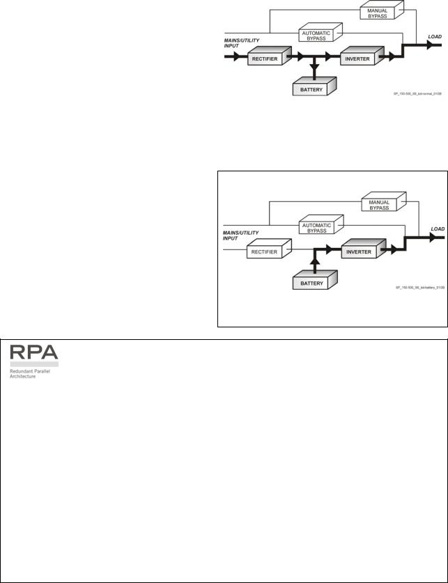
3.2.2 Utility failure operation
When the Utility is no longer within acceptable tolerances, the Battery will provide the DC power to the Inverter.
The Inverter will maintain continuous AC power to the Load until the Battery Voltage reaches the lower limit of the Inverter operation capability.
During the discharge, the LCD screen displays the estimated time the Battery can support the critical load.
Prior to the Battery completely discharging, the "stop operation" alarm (shutdown imminent) warns the operator that the Battery is almost discharged and the UPS is about to shut down.
Fig. 3.2.2-1 Block diagram Utility Failure operation
In case of parallel operation
With a parallel system for power capacity (see Section 3.3)
•With the Bypass Utility power available, a low Battery warning on any unit will cause the Load to be transferred to Utility (after a selectable time delay).
•With Bypass Utility power not available, a low Battery warning on any unit will start the “stop operation” timer (adjustable).
The Load will shut down at the end of the “stop operation” time period.
With a parallel system for redundancy (see Section 3.3)
•When a Battery low warning occurs on a unit not necessary to support the present load, this unit will shut down after a timeout period (selectable).
The Load is shared between the other units
•As the warning occurs on one unit necessary to support the present load, the system starts the "stop operation" timeout (selectable).
The Load will shut down at the end of the “stop operation” time period.
Modifications reserved |
Page 12/82 |
OPM_SGS_USM_M10_M15_0US_V030.doc |
Operating Manual SG Series 100 – 120 - 150 kVA |
3.2.3 |
Utility recovery operation |
|
As soon as the AC input power recovers, the Rectifier will |
|
|
|
||
start automatically, supplying DC power to the Inverter |
|
|
and recharging the Battery. |
|
|
If the Inverter was previously shut down due to low |
|
|
Battery, the Load will be initially powered by Utility |
|
|
through the Automatic Bypass. |
|
|
When the Battery is recharged enough to ensure a |
|
|
minimum time of operation with the present load, the |
|
|
Inverter |
will start automatically and the Load will be |
Fig. 3.2.3-1 Block diagram Utility recovery operation |
transferred back to the Inverter. |
|
|
In case of parallel operation
When the AC input power recovers, the Rectifiers will start up sequentially, according to their number in the parallel system. This minimizes the initial inrush current.
The Inverters will start up automatically, but only when the Battery has recharged enough for a minimum runtime with the present load.
When enough Inverters to supply the Load have been restarted, the Load will be transferred from the
Automatic Bypass back to the Inverter output.
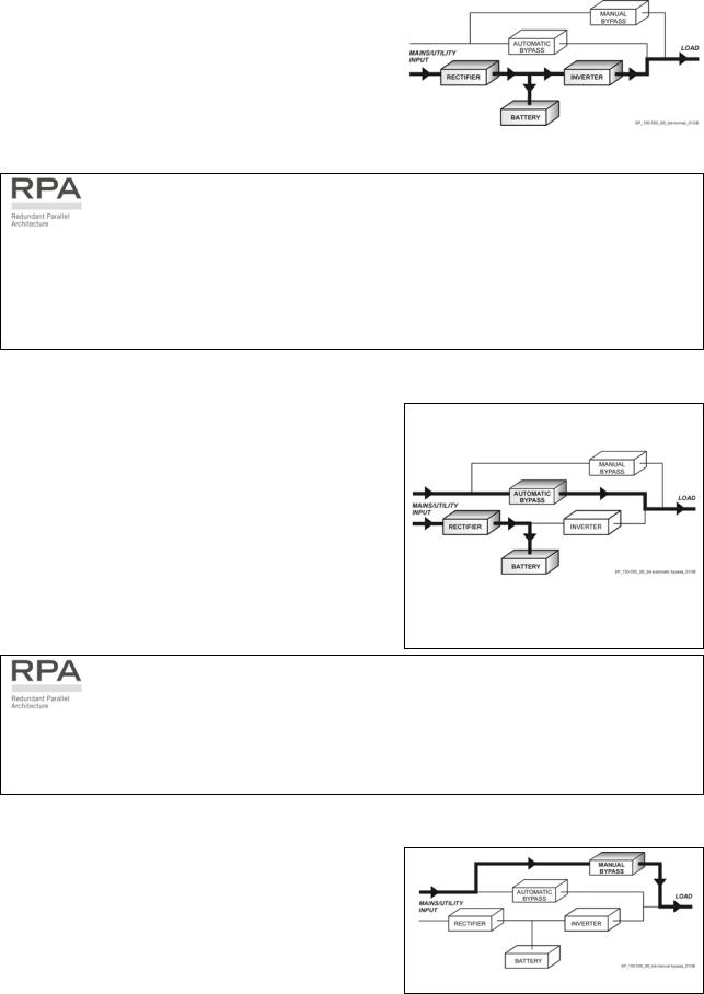
3.2.4 Automatic Bypass |
|
|
In normal operation, the Load is supplied by the Inverter. |
|
|
When the control system detects a fault in the Inverter, |
|
|
an overload condition or a short-circuit condition, the |
|
|
Automatic Bypass will transfer the critical Load to the |
|
|
Utility without interruption. |
|
|
When the Inverter recovers, or the overload or short- |
|
|
circuit condition is corrected, the Load will be |
|
|
automatically transferred back to the Inverter. |
|
|
If the UPS is unable to return to normal mode following |
|
|
an automatic transfer to Bypass mode, an alarm |
Fig. 3.2.4-1 Block diagram Automatic Bypass |
|
condition will be initiated. |
||
|
||
A Manual Bypass (operator initiated) will not be |
|
|
considered as an alarm condition. |
|
In case of parallel operation
Each unit has it’s own internal Bypass. These units are continuously exchanging information, enabling all of the internal Bypass circuits in a parallel system to operate simultaneously.
If the Inverter of a unit fails, it’s Bypass circuit remains available to the parallel system.
It is excluded only if the unit is separated from the common bus by opening it’s output switch Q1.
3.2.5 Manual Bypass
The Manual Bypass circuit consists of Q1 and Q2 manual switches, which permits transfer of the Load directly to the unconditioned AC power without interruption, leaving the UPS available for maintenance.
Fig. 3.2.5-1 Block diagram Manual Bypass
Modifications reserved |
Page 13/82 |
OPM_SGS_USM_M10_M15_0US_V030.doc |
Operating Manual SG Series 100 – 120 - 150 kVA |
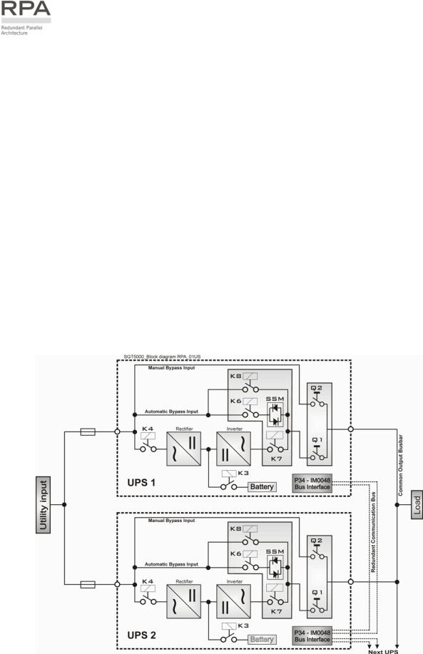
3.3PARALLEL SYSTEM OPERATION
3.3.1 Introduction to the parallel system
Two or more equal power units can be paralleled to increase the output power (paralleling for capacity) or to improve the overall reliability of an UPS system (paralleling for redundancy).
The outputs of parallel units are connected to a common power bus, and in normal operation the units connected on the parallel bus share the Load equally.
The modular concept of SG Series allows parallel operation of up to 8 units, without using paralleling switchgear, external bypass circuits or common control circuitry (see Fig. 3.3.1-1).
Parallel units for power capacity
Several units can be paralleled in order to achieve output power greater than the maximum power of a single unit.
The maximum total power shared between the paralleled units is equal to the total installed nominal power.
In the event of a failure of one unit, the power supplied by the UPS system becomes insufficient and the Load will be transferred to the Utility Bypass source.
Parallel units for redundancy
The nominal power rating of the n+1 out of n redundant paralleled modules must be equal to or greater than the required Load power.
The Load will be equally shared by the n units connected on the output bus.
Should one of the n paralleled units trip Off-line, the remaining (n+1) modules will supply the load, maintaining conditioned power to the critical load.
From this results higher reliability and security for the Load plus a higher MTBF (Mean Time Between Failures).
|
Fig. 3.3.1-1 Block diagram parallel system operation |
Modifications reserved |
Page 14/82 |
OPM_SGS_USM_M10_M15_0US_V030.doc |
Operating Manual SG Series 100 – 120 - 150 kVA |
3.3.2 Features of RPA parallel system
The SG Series parallel system is designed to provide a complete Redundant Parallel Architecture, and is free from common equipment.
Not only the Inverters are redundant, but also the Bypass functions are designed with redundant modular concept.
When one UPS needs maintenance or service, the Load is powered by the other units supplying the
Load bus.
The redundant communication bus to which all units are connected keeps each unit informed about the status of all the other units.
The control panel located on each unit allows controlling and monitoring the status of this unit.
3.3.3 System control
A high-speed redundant, serial communication bus guarantees the exchange of data and thus the communication between the CPU's of each unit.
Each module controls it's own function and operational status and communicates with all other modules, in order to act or react if necessary, adapting it to the new conditions.
3.3.4 Synchronization
All units are identical, but one unit is arbitrarily selected as the reference and all the other units synchronize to this unit, which in turn, synchronizes to the Utility Bypass voltage, as long as the later is within tolerances.
In case of reference failure, another unit in the parallel system is automatically chosen to take over the reference role.
The Bypass Input for all the units of the parallel system must be supplied from the same AC source (no phase shift allowed between them).
3.3.5 Load sharing
On each unit of the parallel system, Inverter Output Voltage and Current are measured and applied to a Load sharing bus.
An eventual difference between the units is therefore automatically equalized.
NOTE !
It is strongly recommended that no transformers, automatic circuit breakers or fuses should be inserted between the unit’s output and the Load common bus bars.
However, it is recommended that a disconnect or isolation switch be inserted.
Modifications reserved |
Page 15/82 |
OPM_SGS_USM_M10_M15_0US_V030.doc |
Operating Manual SG Series 100 – 120 - 150 kVA |
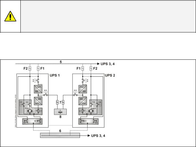
3.4RECTIFIERS PARALLELED ON THE SAME BATTERY
NOTE !
A parallel system with a Common Battery for two or more Rectifiers, requires a particular installation and adequate setting of some parameters, (accessible only through password), and can therefore only be done by a qualified engineer from GE.
Usually each Rectifier-Inverter Unit runs with its own Battery.
In case of parallel units are running with a Common Battery (max. 4 UPS - see Fig 3.4-1), the sharing circuit between individual Rectifier is integrated in the communication bus of the system in order to assure an equal sharing of the Rectifiers output currents.
1 – Rectifier
2 – Inverter
3 – Automatic Bypass
4 – Manual Bypass
5 – Mains Power
6 – Load Bus Bar
7 – External Battery Fuse
8 – Battery
Fig. 3.4-1 Diagram RPA system with Rectifiers on Common Battery
Pay attention to the following recommendations:
•The units delivered for this functioning mode needs a special parameters setting, so they must be prepared in advance before the installation.
•The installation must be performed only with the UPS system must be completely shut down.
•The AC Rectifiers input power (5) must be the same, with clockwise phase rotation for each unit.
•Each Rectifier must be set for the same floating DC voltage and the same Battery current limitation.
•It is recommended to install the fuses / MCB (7) on each line connecting the Rectifiers to the common Battery for maintenance / safety reasons.
•In case one must be powered down for maintenance, switch-OFF the concerned unit before open the DC fuses / MCB on the Battery line (7).
•It is recommended to connect an external NO free contact “Battery Fuses” to the UPS and to enable the function by setting the parameter (see Section 4.1 of the “Installation Guide”).
•If an emergency generator set supply the UPS, and the free contact “Generator ON” is connected to the Customer interface, connect a separate NO free contact on each parallel unit.
•The parameters enabling the Battery test, both manual and automatic, must be set in the same mode on all the units having the Rectifiers on Common Battery.
•Do not connect the temperature sensor for automatic battery floating voltage compensation.
•Do not enable the function Boost charge (parameter 87).
Modifications reserved |
Page 16/82 |
OPM_SGS_USM_M10_M15_0US_V030.doc |
Operating Manual SG Series 100 – 120 - 150 kVA |
3.5RECYCLING AT THE END OF SERVICE LIFE
NOTE !
This product has been designed to respect the environment, using materials and components respecting eco-design rules.
It does not contain CFCs (Carbon Fluor Clorid) or HCFCs (Halogen Carbon Fluor Clorid).
GE, in compliance with environment protection recommends to the User that the UPS equipment, at the end of its service life, must be recovered conforming to the local applicable regulations.
WARNING !
Leads contained in the batteries is a dangerous substance for the environment, therefore it must be correctly recycled by specialised companies!
Modifications reserved |
Page 17/82 |
OPM_SGS_USM_M10_M15_0US_V030.doc |
Operating Manual SG Series 100 – 120 - 150 kVA |

4 LAYOUT
4.1LAYOUT SG Series 100 - 120 - 150 kVA
SGT5000 100-150 UPS GE02 |
SGT5000 100-150 UPS 03 |
Fig. 4.1-1 SG Series general view Fig. 4.1-2 SG Series general view with open doors
Fig. 4.1-3 Manual operated switches
|
|
interface 03 |
|
|
|
100-150 Customer |
|
|
1 |
SGT5000 |
|
|
|
||
|
2 |
|
|
|
3 |
XA |
|
P4 |
4 |
||
|
|||
|
|
||
SNMP |
1 |
XB |
|
|
2 |
|
|
|
3 |
|
|
|
4 |
|
Fig. 4.1-5 Connectivity Rack
Fig. 4.1-4 Control Panel
P4 Customer Interface Board
Q1 UPS output switch
Q2 Manual Bypass switch
SNMP Advanced SNMP Card (option)
XA Terminals for 24VDC Auxiliary Power Supply connection
XB Terminals for EPO (Emergency Power Off) connection
Modifications reserved |
Page 18/82 |
OPM_SGS_USM_M10_M15_0US_V030.doc |
Operating Manual SG Series 100 – 120 - 150 kVA |
5 CONTROL PANEL
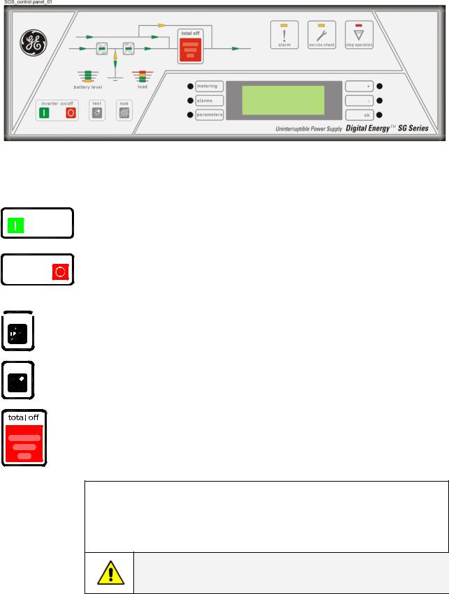
5.1CONTROL PANEL
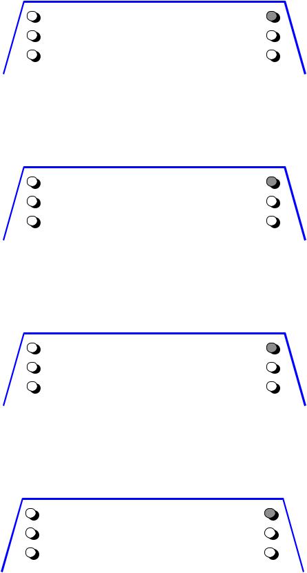
Fig. 5.1-1 Control Panel
5.2TABLE OF FUNCTIONS AND INDICATIONS ON CONTROL PANEL
inverter on/off
inverter on/off
 mute
mute 
test
Key to switch the Inverter ON ( I )
(This key is also used to reset “total off” if pressed simultaneously with total off push button).
Key for Inverter shutdown ( O )
Press key to transfers the Load to Utility.
Keep pressed for 5 seconds to shutdown the Inverter.
This key is also used as the EPO (Emergency Power Off) reset.
Key to reset general alarm and buzzer.
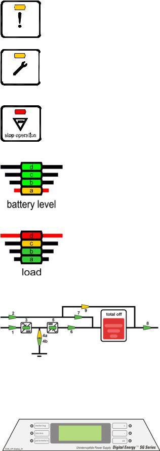
Key to test the control panel LEDs and buzzer.
(Pressing this key causes all the LEDs to light and the buzzer to sound 3 times).
The push-button “total off” is protected by a red cover.
By pressing it, you immediately separate the UPS from Utility and the Load. Attention: “total off” cannot disconnect the UPS from the Load with Q2 closed.
To reset “total off”: push and hold the “total off” push-button and the “I” key (inverter on) simultaneously for some seconds.
 For parallel system: if “total off” is pressed on one unit connected to the parallel bus (switch Q1 closed), all the units are separated from the load.
The “total off” reset must be done only on one unit connected to the parallel bus (switch Q1 closed).
NOTE !
Special care must be taken in using this command, in order to avoid accidental Load disconnection.
Modifications reserved |
Page 19/82 |
OPM_SGS_USM_M10_M15_0US_V030.doc |
Operating Manual SG Series 100 – 120 - 150 kVA |
alarm
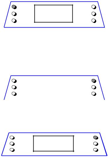
 service check
General alarm condition
It blinks when one or more alarm is activated. The internal buzzer is ON.
The LED remains lighted (with alarm condition still present) and the buzzer stops as the key “mute” has been pressed.
LED ON indicates that a regular maintenance service is needed. May be reset by a service technician only.
See Section 11 – Maintenance.
The LED is ON also when the output switch Q1 is open, indicating that the
Inverter is in service mode, not supplying the load.
a) LED ON indicates that the Battery reserve lasts for only 3 more minutes
(selectable).
b)LED ON in case of overtemperature or overload >125% together with
missing Utility.
After the timeout the Inverter will shut down.
All LEDs ON indicate that the Battery is fully charged
LED a |
Yellow: |
|
|
|
• |
Fixed: |
indicating last 25 % of Battery backup. |
|
• |
Blinking: |
indicating Battery backup ≤ 5%. |
LED b, c, d |
Green: |
|
|
|
• Each one indicating 25 % of Battery backup. |
||
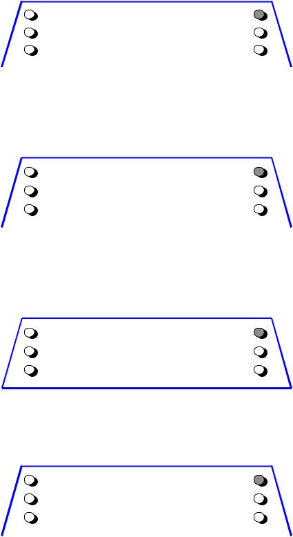
LEDs ON indicate the Load status of the UPS
LED d |
red |
(≥100 % load) |
LED c |
yellow |
(100% load) |
LED b |
green |
(66% load) |
LED a |
green |
(33% load) |
|
LEDs on synoptic diagram |
|||
|
LED 1 |
= Input Utility Rectifier (green) |
||
|
LED 2 |
= Input Utility Bypass (green) |
||
|
LED 3 |
= |
Rectifier ON (green) |
|
|
LED 4a |
= |
Discharging (yellow) |
|
|
LED 4b |
= |
Charging (green) |
|
|
LED 5 |
= |
Inverter ON (green) |
|
|
LED 6 |
= Load on Inverter (green) |
||
Fig. 5.2-1 LEDs on synoptic diagram |
LED 7 |
= Load on Utility (green) |
||
|
LED 8 |
= Output Load Voltage (green) |
||
|
LED 9 |
= |
Manual Bypass (Q2) ON (yellow) |
|
|
User LCD Interface |
|||
|
Consist of an LCD screen, 4 lines with 20 |
|||
|
characters each and six keys. It offers: |
|||
|
• UPS operating, AC and DC metering |
|||
|
information. |
|||
Fig. 5.2-2 LCD screen |
• History of events (alarms and messages). |
|||
• Functionality can be programmed to meet |
||||
|
||||
|
customer needs by changing parameters. |
|||
Modifications reserved |
|
|
Page 20/82 |
|
OPM_SGS_USM_M10_M15_0US_V030.doc |
|
|
Operating Manual SG Series 100 – 120 - 150 kVA |
|
6 LCD SCREEN
The user interface consists of a back lit LCD screen having:
•4 lines with 20 characters (standard version for Latin characters).
and
•6 keys (the function is described for each operating mode).
The operation is extremely simple and is structured on three important main menus related to the UPS operation, as follows:
metering A UPS must offer some metering information for the user to be able to examine the operating status at any time.
alarms In the event of Utility failures or abnormal functioning, the UPS must keep a history of what has happened as a series of events.
parameters The user must be able to program certain functions of the UPS (user parameters, accessible without password) to his needs.
LCD screen standard version
metering |
LCD screen |
+ |
alarms |
4 rows x |
– |
parameters |
20 characters |
ok |
|
||
|
|
|
The 3 buttons existing on the left side of the screen are used to activate the operating modes, while the buttons on the right side are used to carry out functions inside these operating modes.
Modifications reserved |
Page 21/82 |
OPM_SGS_USM_M10_M15_0US_V030.doc |
Operating Manual SG Series 100 – 120 - 150 kVA |
6.1METERING MODE
The metering mode is entered any time the metering button is pressed.
While in this mode the LCD will display a series of screens containing metering information. In this mode the buttons perform the following functions:
metering |
Scrolls forward to the next screen. |
alarms |
Abandons the metering mode and enters the alarms mode. |
parameters |
Abandons the metering mode and enters the parameters mode. |
+ |
Scrolls forward to the next screen. |
– |
Scrolls backward to the previous screen. |
ok |
Displays the main screen for this mode. |
Main screen
This screen displays the current status of the UPS in a condensed form.
The information offered by this screen consists of:
•The type of the machine: Family name, series number (P + unit number for parallel version from 1 to 8) and power range.
•The status of the load.
•The Load amount as a percentage of the nominal Load (referred to the most loaded phase).
•The estimated Battery backup time in minutes with the present load.
metering |
SG Series S0 100kVA |
+ |
alarms |
LOAD ON INVERTER |
– |
LOAD = 84% |
||
parameters |
Autonomie = 12min |
ok |
|
Battery data screen
This screen displays:
•The Battery voltage.
•The Battery Current (negative values correspond to the discharge of the Battery).
•The temperature of the Battery (XXX indicates sensor disabled).
•The current charge level.
•The estimated backup time with the present load.
metering |
Ub=540V |
Ib= |
+ 15A |
+ |
|
alarms |
Battery |
Temp= |
+ 20°C |
– |
|
Charge |
Level= |
87% |
|||
parameters |
Autonomy |
= |
12min |
ok |
|
|
|
|
|
||
|
|
|
|
|
|
Bypass Utility data screen
This screen refers to the AC source supplying the Bypass. This screen displays:
•The frequency.
•The voltage levels of the three phase voltages.
m etering |
UTILITY |
+ |
alarm s |
f = 60.0Hz |
– |
U1=276V U2=275V |
||
param eters |
U3=277V |
ok |
|
||
Modifications reserved |
|
Page 22/82 |
OPM_SGS_USM_M10_M15_0US_V030.doc |
Operating Manual SG Series 100 – 120 - 150 kVA |
Rectifier Utility data screen
This screen refers to the AC source supplying the Rectifier.
This screen displays:
•Iout1 = output current Rectifier Bridge.
•Iout2 = output current 2nd Rectifier Bridge (optional 12 pulse Rectifiers only).
•The voltage levels between the three phases (line-to-line).
•The input frequency of the Rectifier.
metering |
RECTIFIER |
+ |
|
alarms |
U12=481V |
Iout1 =133A |
– |
U23=480V |
Iout2 = 0A |
||
parameters |
U31=482V |
f=60.0Hz |
ok |
|
|
||
|
|
|
|
Inverter data screen
This screen displays:
•The voltage level of the three phase voltages (line-to-neutral).
•The output frequency of the Inverter.
•The synchronization status of the Inverter with respect to Utility.
metering |
INVERTER: |
U1=277V |
+ |
alarms |
U2= 277V |
U3=277V |
– |
Frequency = 60.0Hz |
|||
parameters |
Synchronized |
ok |
|
|
|
||
|
|
|
|
Status Load screen
This screen displays:
•The Load level in kVA (for RPA: only this unit).
•The Load level as a percentage of the nominal rated Load (for RPA: only this unit).
•The source of the power supplied to the Load.
metering |
|
LOAD ON UPS |
+ |
|
alarms |
Load |
= |
80.04kVA |
– |
Percentage = |
80% |
|||
parameters |
LOAD ON INVERTER |
ok |
||
|
|
|
||
Load on phases screen 1
This screen displays for each phase:
•The output phase voltage and current as RMS values (for RPA: total value of Parallel System).
•The output Load as percent (for RPA: respect to the rated power of Parallel System).
metering |
LOAD ON PHASES |
+ |
|||
alarms |
U1=277V |
I=101A |
84% |
– |
|
U2=277V |
I= 95A |
79% |
|||
|
|||||
parameters |
U3=277V |
I= 93A |
77% |
ok |
|
|
|
|
|||
|
|
|
|
|
|
Modifications reserved |
Page 23/82 |
OPM_SGS_USM_M10_M15_0US_V030.doc |
Operating Manual SG Series 100 – 120 - 150 kVA |
Load on phases screen 2
This screen displays for each phase:
•The Load active power (kW) (for RPA: total value of Parallel System).
•The Load apparent power (kVA) (for RPA: total value of Parallel System).
metering |
LOAD ON PHASES |
+ |
|
alarms |
L1= 22.37kW |
27.97kVA |
– |
L2= 21.05kW |
26.31kVA |
||
parameters |
L3= 20.61kW |
25.76kVA |
ok |
|
|
||
|
|
|
|
Miscellaneous screen
This screen displays:
•The temperature of the Inverter Bridge.
•The total operating time for the UPS (in hours).
•The total operating time for the Inverter (in hours).
metering |
MISCELLANEOUS |
+ |
|
alarms |
InvHeatsink = |
45°C |
– |
UpsOperTime= |
3125h |
||
parameters |
InvOperTime = |
2135h |
ok |
|
|
||
|
|
|
|
Utility Faults Statistics screen
This screen displays:
•The total number of minor Utility faults (Bypass Utility out of tolerance faults).
•The total number of major Utility faults (Rectifier Utility out of tolerance faults).
•The total number of detected output overloads.
metering |
UTILITY FAULTS STAT. |
+ |
||
alarms |
Minor |
= |
43210 |
– |
Major |
= |
11267 |
||
parameters |
Overloads= |
654 |
ok |
|
|
|
|
||
|
|
|
|
|
UPS identification screen
This screen displays:
•The UPS family and the power range.
•The software version.
•The serial number.
metering |
UPS IDENTIFICATION |
+ |
alarms |
SG Series S0 100kVA |
– |
SW Version: x.xx |
||
parameters |
S/N: P0100-2006-0001 |
ok |
|
||
|
|
|
Modifications reserved |
Page 24/82 |
OPM_SGS_USM_M10_M15_0US_V030.doc |
Operating Manual SG Series 100 – 120 - 150 kVA |
6.2ALARMS
The alarms mode is entered any time the alarms button is pressed.
The LCD will display a series of screens corresponding to the last 256 events, one event per screen.
The buttons perform the following functions:
metering |
Abandons alarms mode and enters metering mode. |
alarms |
Next screen. |
parameters |
Abandons the alarms mode and enters the parameters mode. |
+ |
Scrolls forward to the next screen. |
– |
Scrolls backward to the previous screen. |
ok |
Display the main screen for this mode. |
The events displayed are the standard GE events as described in the Section 6.7 - EVENTS (Alarms and Messages).
The information displayed includes:
•The exact date and time when the event occurred.
•The number of the event, 255 being the most recent event, and 0 the oldest.
•The standard GE code for the event and the machine status word.
•An explicit text description of the event.
metering |
01.01.2006 22:11:51 |
+ |
alarms |
NR=255 Status=4A61 |
– |
4115:LOW BATTERY |
||
parameters |
VOLTAGE |
ok |
|
The initial screen of this mode is the one showing the most recent event.
Modifications reserved |
Page 25/82 |
OPM_SGS_USM_M10_M15_0US_V030.doc |
Operating Manual SG Series 100 – 120 - 150 kVA |
Loading...