

Page 1

Gateway™910 Series
System Manual
September 2001
8508341
Page 2

Notices
Copyright © 2001 Gateway, Inc.
All Rights Reserved
4545 Town Centre Court
San Diego, CA 92121 USA
All Rights Reserved
This publication is protected by copyright and all rights are reserved. No part of it may be reproduced or
transmitted by any means or in any form, without prior consent in writing from Gateway.
The information in this manual has been carefully checkedandis believed to be accurate. However, changes
are made periodically. These changes are incorporated in newer publication editions. Gateway may improve
and/or change products described in this publication at any time. Due to continuing system improvements,
Gatewayis not responsible for inaccurate information which may appear in this manual. For the latest product
updates, consult the Gateway Web site at www.gateway.com. In no event will Gateway be liable for direct,
indirect, special, exemplary, incidental, or consequential damages resulting from any defect or omission in
this manual, even if advised of the possibility of such damages.
In the interest of continued product development, Gateway reserves the right to make improvements in this
manual and the products it describes at any time, without notices or obligation.
Trademark Acknowledgments
1-800-GATEWAY, ActiveCPR, ALR, AnyKey, black-and-white spot design, CrystalScan, Destination, DestiVu,
EZ Pad, EZ Point, Field Mouse, Gateway 2000, Gateway Country, gateway.net, Gateway stylized logo, Perfect
Scholar, Solo, TelePath, Vivitron, stylized “G” design, and “You’ve got a friend in the business” slogan are
registered trademarks and black-and-white spotted box logo, GATEWAY, Gateway Astro, Gateway@Work,
Gateway Connected touch pad, Gateway Connected music player, Gateway Cyber:)Ware, Gateway
Education:)Ware, Gateway Flex Case, Gateway Gaming:)Ware, Gateway GoBack, Gateway Gold, Gateway
Learning:)Ware, Gateway Magazine, Gateway Micro Server, Gateway Money:)Ware, Gateway Music:)Ware,
Gateway Networking Solutions, G ateway Online Network (O.N.) solution, Gateway Photo:)Ware, Gateway
Professional PCs, Gateway Profile, Gateway Solo, green stylized GATEWAY, green stylized Gateway logo,
Gateway Teacher:)Ware, Gateway Video:)Ware, HelpSpot, InforManager, Just click it!, Learn@Gateway, Kids
BackPack, People Rule, SERVE-TO-ORDER, Server Watchdog, SpotShop, Spotshop.com, and Your:)Ware
are trademarks of Gateway, Inc. Intel, Intel Inside logo, and Pentium are registered trademarks and MMX is
a trademark of Intel Corporation. Microsoft, MS, MS-DOS, and Windows are trademarks or registered
trademarks of Microsoft Corporation. All other product names mentioned herein are used for identification
purposes only, and may be the trademarks or registered trademarks of their respective companies.
Page 3

Contents
Preface..............................................................v
Conventions used in this manual .......................................v
Getting additional information . . ........................................vi
1 Features .........................................................1
Standardfeatures ...................................................1
Front .............................................................2
Back..............................................................3
Interior ............................................................5
System board ......................................................7
2SystemSetup...................................................9
Settingupyourserver................................................9
Startingyourserver.................................................10
Understanding the Power-On Self-Test ..............................11
Settinguptheoperatingsystem....................................11
Turningoffyourserver ..............................................12
Restartingyourserver ...............................................13
3 Case Access ...................................................15
Preventingstaticelectricitydischarge ...................................15
Openingthecase ..................................................16
Removingthecoverpanel ........................................17
Removingthebezel .............................................19
Closingthecase ...................................................21
Reinstallingthebezel ............................................21
Reinstalling the cover panel .......................................22
4 Replacing or Adding System Components .....................23
Replacing or adding drives ...........................................23
Preparing to replace or add a drive . . . ..............................23
Drivecablingconsiderations .......................................24
ReplacingtheCDdrive...........................................25
Replacingthediskettedrive .......................................28
Addinga5.25-inchor3.5-inchremovablemediadrive ..................30
Replacingtheharddrive..........................................33
Adding an additional hard drive ....................................35
Replacing or adding memory . . .......................................37
Contents i
Page 4

Replacingtheprocessor..............................................40
Adding or replacing expansion cards ....................................44
Replacingthebattery ................................................49
Replacing the system board ...........................................52
Replacingthepowersupply ...........................................55
5 Using the BIOS Setup Utility ....................................57
About the BIOS Setup utility ...........................................57
Settingthesystemboardjumpers ......................................60
Updating the BIOS . . . ...............................................61
Recovering from a failed BIOS update . . .............................61
6 Managing Your Server ..........................................63
Protecting against power source problems . . .............................63
Surge suppressors ...............................................63
Line conditioners . ...............................................64
Uninterruptible power supplies ......................................64
Maintaining and managing your hard drive . . .............................65
Hard drive maintenance utility ......................................65
Harddrivemanagementpractices...................................66
Protectingtheserverfromviruses...................................68
Systemadministrationandcontrol ......................................70
ManageX Event Manager . . . ......................................70
SNMPagent ....................................................70
Serversecurity ..................................................71
Systemrecovery ....................................................72
Creatingastartupdiskette .........................................72
Keeping a record of system configuration .............................72
UsingyourServerCompanionCD ..................................72
7 Troubleshooting ................................................73
Introduction ........................................................73
Troubleshootingchecklist .............................................73
Verifyingyourconfiguration ........................................74
Troubleshooting guidelines . . ......................................74
Troubleshooting the battery installation . . .............................74
CDdriveproblems ..................................................75
Harddriveproblems .................................................76
Memoryandprocessorproblems.......................................77
Modem problems ...................................................78
Peripheral device/adapter problems .....................................79
Printerproblems ....................................................81
ii Contents
Page 5

Systemproblems...................................................82
Videoproblems ....................................................84
Error messages ....................................................87
Beepcodes .......................................................91
A Safety, Regulatory, and Legal Information .....................93
B Reference Data ................................................105
Specifications.....................................................105
Systemspecifications ...........................................106
Mechanical specifications . . ......................................107
Environmentalspecifications......................................107
Electricalspecifications ..........................................108
System I/O addresses ..............................................109
Memorymap .....................................................111
Interrupts ........................................................112
DMAusage ......................................................113
Index..............................................................115
Contents iii
Page 6

iv Contents
Page 7
Preface
Conventions used in this manual
Throughout this manual, you will see the following conventions:
Convention Description
ENTER Keyboard key names are printed in small capitals.
C
TRL+ALT+DEL A plus sign means to press the keys at the same time.
Setup Commands to be entered, options to select, and messages that appear
on your monitor are printed in bold.
User’s Guide Names of publications are printed in italic.
Viewpoint All references to front, rear, left, or right on the server are based on the
server being in a normal, upright position, as viewed from the front.
Defined terms When new terms are introduced and defined, they will be shown in italic.
Important A note labeled important informs you of special
circumstances.
Caution A caution warns you of possible damage to equipment or
loss of data.
Warning A warning indicates the possibility of personal injury.
Conventions used in this manual v
Page 8

Getting additional information
Log on to the technical support area of www.gatewayatwork.com to find
information about your server or other Gateway products. Some types of
information that you can access are:
■ Hardware driver and program updates
■ Technical tips
■ Service agreement information
■ Technical documents and component information
■ Frequently asked questions (FAQs)
■ Documentation for peripheral devices or optional components
■ Online technical support
Y ou can find additional documentation on the Server Companion CD (SCCD)
that came with your server.
vi Preface
Page 9

Features
Standard features
1
■ Intel
■ Four dual in-line memory module (DIMM) sockets that support as much
■ Integrated ATI
■ Integrated Intel
■ Serverworks
■ Three 32-bit/33 MHz and two 64-bit/66 MHz PCI slots that support
■ One 3.5 inch diskette drive, one CD drive, and one hard drive
■ Keyboard port, mouse port, one serial port, parallel port, video port, Local
®
Celeron™ or Pentium®III processor
as 2 gigabytes (GB) of PC133 Synchronous Dynamic Random Access
Memory (SDRAM)
®
video controller - Rage XL 4 MB PC100 SDRAM
®
10/100 Mbit per second Ethernet network support
™
Champion LC chip set
full-length, full-height PCI expansion cards
Area Network (LAN) port, four Universal Serial Bus (USB) ports (two front
and two back)
Standard features 1
Page 10
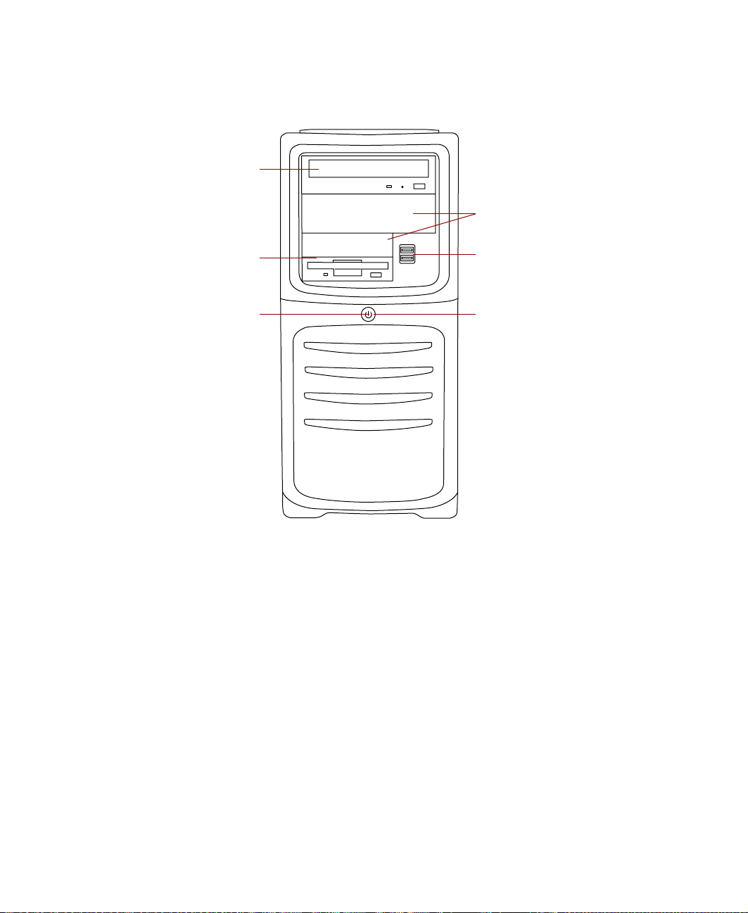
Front
CD drive
Additional
drive bays
Diskette drive
Power LED
CD drive reads data or plays audio CDs.
Diskette drive writes to and reads from 3.5-inch, 1.44 MB diskettes.
Power LED glows green when the server is on.
Additional drive bays lets you install additional 5.25-inch or 3.5-inch drives.
USB ports connect external Plug-n-Play devices that are automatically
configured when they are plugged into the server through one of these ports.
USB keyboards and mice are not supported. Use only PS/2 versions.
USB ports
Power button
Power button turns the server on and off. It also enables sleep-mode in some
operating systems.
2 Features
Page 11
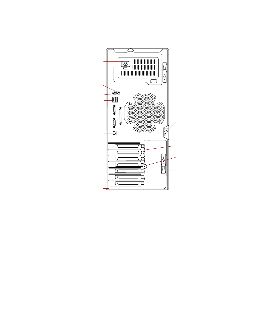
Back
Power connector
Voltage selector
switch
Mouse port
Keyboard port
USB ports
Serial port
Parallel port
Video port
RJ-45 LAN port
Release tab
Cover panel
thumbscrew
Kensington
lock slot
Card retainer
Expansion
card slots
Card retainer
thumbscrew
Release tab
Power connector connects to the server power cord. The other end of the
power cord plugs into an AC outlet or power strip.
Voltage selector switch sets the voltage for your area, either 115V or 230V.
®
Mouse port connects to a PS/2
(Personal System/2®) -compatible mouse.
Keyboard port connects to a PS/2-compatible keyboard.
USB ports connect to external Plug-n-Play devices that are automatically
configured when they are plugged into the server through one of these ports.
USB keyboards and mice are not supported. Use only PS/2 versions.
Serial port connects to serial devices.
Parallel port connects to a printer or other parallel device.
Back 3
Page 12

Video por t connects to the monitor interface cable.
RJ-45 LAN connector connects to the Ethernet network cable. The adjacent
indicator LEDs show LAN activity (yellow) and 100 Mbit speed (green).
Expansion card slots let you add additional cards to the system board.
Release tabs let you remove the cover panel.
Cover panel thumbscrew is used to securely fasten the cover panel to the
chassis.
Kensington lock slot lets you use a cable lock to secure the server and prevent
the cover panel from being removed.
Card retainer is used to secure expansion cards in place.
Card retainer thumbscrew is removed to open the card retainer.
4 Features
Page 13

Interior
Power
supply
System
fan
System
board
Power supply
release latch
Upper drive
cage
Drive r elease
latch
Hard drive
Bezel tab
Drive r elease
latch
Lower drive
cage
Bezel
Bezel tab
Power supply is installed on the inside of the back panel and provides power
to the system board and all internal components.
System fan is installed beneath the power supply and vents heated air out
of the server.
System board is installed on the chassis frame stand-offs and connects to all
internal components with cable connectors.
Power supply release latch is used to secure the power supply in place.
Upper drive cage contains the diskette and CD drive and provides a mounting
location for an additional 5.25-inch and 3.5-inch drive.
Drive release latches are used to secure drives in place. There are three latches
on the upper drive cage and three on the lower drive cage. Locked and
unlocked positions are indicated by an open or closed padlock icon.
Hard drive is located in the lower drive cage and connects to the power supply
and system board.
Interior 5
Page 14

Lower drive cage is located inside the chassis beneath the diskette drive and
contains the hard drive. It provides a mounting location for two additional
3.5-inch drives.
Bezel mounts to the front of the chassis.
Bezel tabs hold the bezel into place on the chassis.
6 Features
Page 15

System board
A B
V
U
T
S
R
Q
P
O
C
DE
F
G
H
I
J
A Keyboard port
B Mouse port
C Processor socket
D DIMM slots
E Main power connector
F Secondary IDE connector
G Primary IDE connector
N
M
LK
System board 7
Page 16

H Diskette drive connector
I Front panel connector
J Thumbscrew installation hole
K Front panel USB connector
L Hardware management connector
M Server configuration jumper block
N Battery
O 32-bit PCI slots
P 64-bit PCI slots
Q RJ-45 LAN connector
R Video por t
S Processor fan connector
T Parallel port
U Serial port
V Back panel USB connector
8 Features
Page 17

S
y
s
t
e
m
S
e
t
u
p
Settingupyourserver
Use the instructions on the poster that came with your server to set up your
hardware.
You can improve the safety of your working environment before setting up
your hardware by following these guidelines:
■ Use a clean, flat, and stable surface for your server . Allow at least 12 inches
at the rear of the server for cabling and air circulation.
■ Obtain a grounded (three-prong) AC surge-protected power strip. A
surge-protected power strip helps protect against AC power fluctuations.
■ Protect your server from extreme temperature and humidity. Do not
expose your server to direct sunlight, heater ducts, or other
heat-generating objects.
■ Keep your server away from equipment that generates magnetic fields,
such as unshielded stereo speakers. Even a telephone placed too close to
the server may cause interference.
2
■ Plug the server into a wall outlet or power strip that is easily accessible.
Important Keep the server boxes and packing material in case you
need to send the server to Gateway for repairs. If you
return your server in different packaging, your warranty
may be voided.
Setting up your server 9
Page 18

Starting yourserver
Before you start your server for the first time:
■ Make sure that the voltage selector switch on the back of the server is
set to the correct voltage for your area. This switch is set at the factory
to the correct voltage (see “Back” on page 3 for the voltage selector switch
location).
■ Make sure all cables are firmly connected to the proper ports on the back
of the server.
Caution Make sure your server and peripherals are turned off and
unplugged from the power outlet when you connect
peripherals to the server, or you might damage the server
or the peripherals.
■ Make sure the server and monitor are plugged into an AC outlet or power
strip and that the power strip is turned on.
To start the ser ver:
1 Turn on any components connected to the server, such as a monitor,
printer or scanner.
2 Turn on the server. The power indicator light-emitting diode (LED) on
the front of the server remains lit (green) when the power is on.
If nothing happens when you turn on the server:
■ Make sure that the power cables are securely plugged in and that
your power strip (if you are using one) is plugged in and turned on.
■ Make sure the monitor is connected to the server, plugged into the
power strip or AC outlet, and turned on. You may also need to
adjust the brightness and contrast controls on the monitor.
10 System Setup
Page 19

Understanding the Power-OnSelf-Test
When you turn on your server, the power-on self-test (POST) routine checks
the server memory and components. If POST finds any problems, the server
displays error messages. Write down any error messages that you see. If you
continue to have problems, these error messages may help Gateway T echnical
Support diagnose the cause.
Press the T
mode (no startup information displayed).
AB key to see the startup POST messages. The default setting is quiet
Important The server s tarts very quickly. If your monitor requires time
to warm up, you may not see the messages that are
displayedduringstartup.Ifyouarehavingproblems,you
may need to wait for the monitor to warm up, then restart
the server. If you are trying to enter Setup, press F1 before
the monitor warms up.
Setting up the operating system
The first time you start your server, the operating system takes a few minutes
to set up. Refer to your operating system documentation for specific questions
regarding the operating system.
Important Any ID or key numbers requested to complete the
operating system setup are on a sticker attached to the
server.
To complete the operating system setup for Windows 2000 Server:
1 After the server starts, the start-up wizard opens. Continue by clicking
Next.
2 Type the requested information in the appropriate text boxes. When you
have finished typing the information, continue by clicking
Next.
3 Continue following the instructions and selecting options in the start-up
wizard dialog boxes, clicking
the wizard tells you to restart your server.
If you need to return to the previous dialog box to change any of your
entries, click
Back.
Next to move through the dialog boxes, until
Starting your server 11
Page 20
4 Restart your ser ver. The setup is complete.
Important For other operating systems, refer to the appropriate
operating system software manual for setup instructions.
Turning off your server
Every time you turn off your server, shut down the operating system first.
You may lose data if you do not follow the proper procedure.
To turn off your server in Windows 2000 Server:
1 Click Start, then select Shut Down, then Shut down.
2 Click OK. The operating system shutdowns and the server turns off.
3 Turn off the monitor and peripheral devices.
Warning When you turn the server off, some electric current still
flows through the server. Before opening the server case
or connecting or removing any peripherals, turn off the
server, then unplug the power cord and modem cord (if
installed) or you may get an electric shock.
Caution When you routinely turn off your server (daily or weekly),
Important For other operating systems, refer to the appropriate
12 System Setup
do not unplug the server or use the On/Off switch on the
power strip. Regularly cutting off all power to your server
may cause premature battery failure.
operating system software manual for instructions.
Page 21

Restarting yourserver
If your server does not respond to keyboard or mouse input, you may have
to close programs that are not responding. If closing unresponsive programs
does not restore your server to normal operation, you may have to restart the
server.
To close unresponsive programs and restart Windows 2000 Server:
1 Press CTRL+ALT+DEL. A window opens that lets you close a program that
is not responding.
2 Click Task Manager, then select the program that is not responding.
3 Close the program by clicking End Task.
4 If the server does not respond, turn off the server power, wait ten seconds,
turn the power on again.
Important If the server does not turn off immediately, you may need
to hold the power button down for a few seconds to turn
the server off.
As a part of the regular startup process, a program to check the disk status
runs automatically. When the checks are finished, Windows starts.
Important For other operating systems, refer to the appropriate
operating system software manual for instructions.
Restarting your server 13
Page 22

14 System Setup
Page 23

3
Case Access
Preventing static electricity discharge
Before opening the server case, follow these precautions to prevent damage
from static electricity, also called electrostatic discharge (ESD). When opening
your server case, always perform the following procedure.
Caution Static electricity can permanently damage electronic
components in your server. Prevent electrostatic damage
to your server by following static electricity precautions
every time you open your server case.
To prevent damage from static electricity discharge:
1 Wear a grounding wrist strap (available at most electronics stores).
2 Turn off the server power.
3 Discharge any static electricity harmlessly by touch a bare metal surface,
such as the back of the server.
4 Unplug all power cords from AC outlets and disconnect the modem cable
(if installed).
Warning Toavoid the risk of electric shock, do not insert any object
into the vent holes of the power supply.
Preventing static electricity discharge 15
Page 24

Also follow these static electricity precautions:
■ Avoid static-causing surfaces and items in your work area, such as plastic
and packing foam.
■ Remove parts from their antistatic bags or containers only when you are
ready to use them. Do not lay parts on the outside of an antistatic bag
or container because only the inside provides antistatic protection.
■ Always hold cards by their edges and their metal mounting brackets.
Avoid touching components on the cards and the edge connectors that
connect to expansion slots. Never slide cards or other parts over any
surface.
Opening the case
All references to front, rear, left, or right on the server are based on the server
being in a normal, upright position, as viewed from the front.
To work on the internal components of the server, you must open the case,
which has two main removable parts:
■ A cover panel that permits access to the interior of the case
■ A bezel that covers the front of the chassis
Because the components inside your server are extremely sensitive to static
electricity, make sure you follow the precautions at the beginning of this
chapter for avoiding static electricity damage.
Only qualified personnel should open the server for maintenance. If you are
qualified to maintain the server yourself, make sure you are properly grounded
before opening the server cover panel.
Warning Avoid exposure to dangerous electrical voltages and
16 Case Access
movingparts by turning off your server and unplugging the
powercordand modem cable (if installed)beforeremoving
the cover.
Page 25
Removing the coverpanel
To remove the cover panel:
1 Observe the safety and ESD precautions in “Preventing static electricity
discharge” on page 15.
2 Turn off the server, then disconnect the power cord(s), modem cable (if
installed), and all external devices.
3 Carefully place the server on its right side with the back of the server
facing you.
4 Unlock the chassis (if applicable).
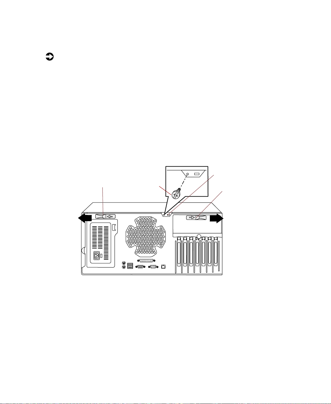
5 Remove the cover panel thumbscrew.
6 Slide the two release tabs on the back panel outward.
Release tab
Cover panel
thumbscrew
Kensington lock
slot
Release tab
Opening the case 17
Page 26
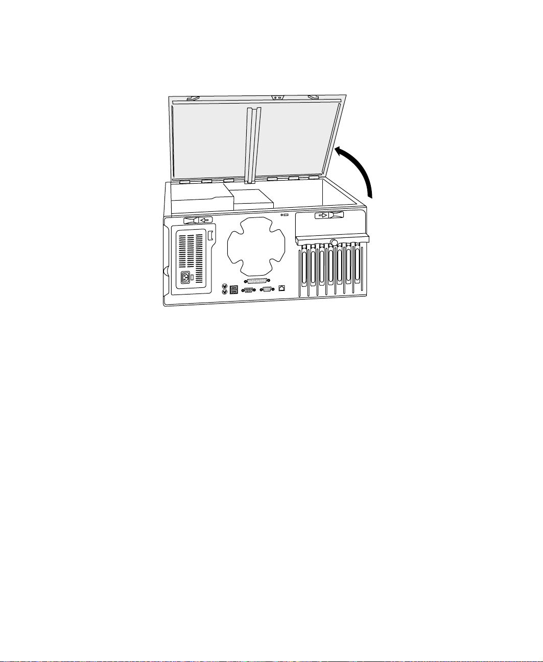
7 Lift the back edge of the cover panel, then remove the panel from the
server.
18 Case Access
Page 27
Removing the bezel
To remove the bezel:
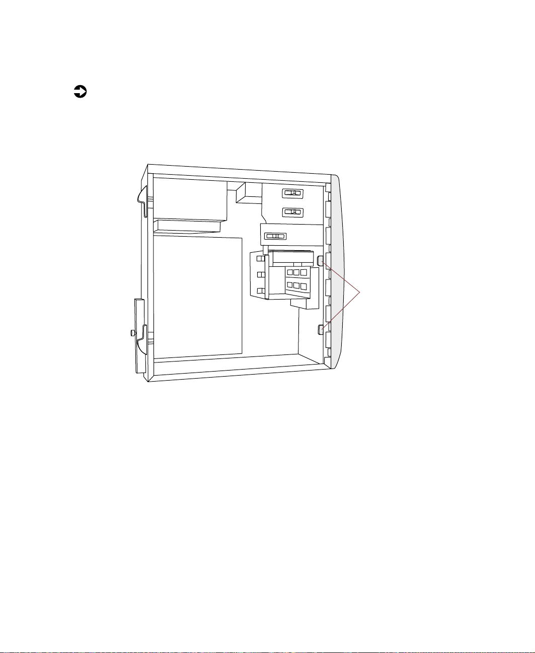
1 With the cover panel removed, carefully return the server to the upright
position with the open side facing you.
2 Disengage the bezel tabs by pressing on each tab.
Bezel tabs
Opening the case 19
Page 28
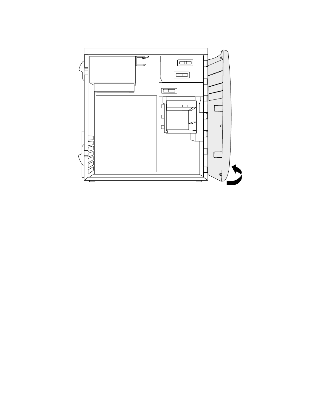
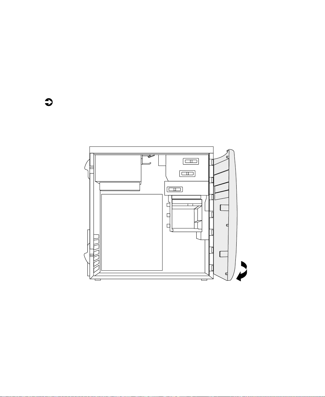
3 Swing the bezel outward and disengage the bezel from the hinges.
20 Case Access
Page 29
Closing the case
Reinstall the cover as soon as you finish installing or removing components
so that dust and dirt do not collect inside the server.
Reinstalling the bezel
To reinstall the bezel:
1 Make sure the chassis is in the upright position.
2 Holding the bezel parallel with the front of the chassis, align the hinge
tabs with the chassis slots, then place the hinge tabs in the slots.
3 Swing the bezel toward the chassis until the bezel tabs snap into place.
Closing the case 21
Page 30
Reinstalling the cover panel
To reinstall the cover panel:
1 Carefully place the ser ver on its right side.
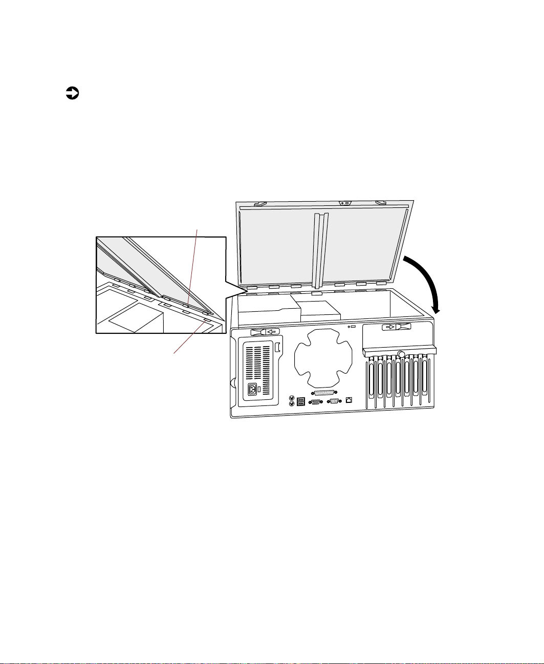
2 Align the cover panel tabs with the chassis slots, then install the cover
panel into the chassis.
3 Swing the cover panel down and press it firmly into place. The two release
tabs should snap into place, indicating that the panel is secure.
Cover panel tabs
Chassis slots
4 Reinstall the cover panel thumbscrew.
5 Carefully return the ser ver to the upright position.
22 Case Access
Page 31

Replacing or Adding System Components
Replacing or adding drives
Locked and unlocked positions of drive release latches are represented by a
padlock icon in either the unlocked or locked position.
Preparing to replace or add a drive
One 3.5-inch hard drive, one CD drive, and one 3.5-inch diskette drive are
included with the server. Note that the diskette controller supports one
diskette drive. You can add additional drives of the following types:
■ One- 1-inch height, removable media 3.5-inch storage device (upper drive
cage)
4
■ One- 1.6-inch half-height, removable media 5.25-inch device (upper
drive cage)
■ Two- 1-inch height, internal 3.5-inch hard drives (lower drive cage)
Replacing or adding drives 23
Page 32

As you prepare to install drives, keep the following in mind:
■ When you remove and install drives, use an antistatic wrist strap.
■ If you remove a drive, place it in an antistatic bag or container.
■ Before you install a drive, see the drive documentation for information
on configuring the drive, setting any jumpers on the drive, and attaching
cables to the drive.
■ If you are installing a drive that requires a controller card, install the card
before you install the drive.
■ IDE hard drives can be configured as single, master, slave, or cable-select.
IDE CD drives can be configured as master, slave, or cable-select.
Configure the drives by using the drive-select jumpers located on the
drives.
■ If cable-select is available (drive assignments will be marked on the
cable), the IDE cable automatically assigns master/slave positions to
the drives they connect. You can override these assignments using
the jumpers on the drives.
■ If cable-select is not available, and only one drive is attached to a
controller cable, configure the drive as master if it is a CD drive. If
two drives of any type are attached to the cable, configure one as
master and one as slave.
■ One or more controllers are needed to support a full-compliment
of drives. In addition, additional cables (available from Gateway) are
required to support a drive configuration beyond the five supported
by the integrated controllers on the system board.
■ You may need to configure the drives you install using the BIOS Setup
utility. Press F1 at start up to open the BIOS Setup utility.
Drive cabling considerations
Your server includes different types of drive cables. Each drive cable is clearly
labeled, indicating the cable-type and showing which end is connected to the
appropriate connector on the system board and which end is connected to
the drive.
Use the diskette drive cable to connect the diskette drive. Use the standard
IDE cable (labeled secondary IDE) to connect IDE devices such as CD drives
and standard IDE hard drives. Use the 40-pin connector, 80-pin conductor
cable (labeled primary IDE) to connect DMA-100 -compatible hard drives.
24 Replacing or Adding System Components
Page 33

Replacing the CD drive
All drives are secured in the chassis by a drive release latch on the side of the
drive bays. The CD drive is included in the original configuration. If you need
to replace the CD drive, perform the following instructions.
To remove the CD drive:
1 Observe the safety and ESD precautions in “Preventing static electricity
discharge” on page 15.
2 Turn off the server, then disconnect the power cord(s), modem cable (if
installed), and all external devices.
3 Remove the cover panel. (See “Removing the cover panel” on page 17.)
4 Remove the bezel. (See “Removing the bezel” on page 19.)
5 Disconnect the power, audio, and data cables, noting their locations and
orientations. (You will reconnect these cables after you install the new
drive.)
6 Push the drive release latch toward the back of the server (unlocked
position).
7 Pull the drive out of the chassis and place it in an antistatic container.
Replacing or adding drives 25
Page 34

Drive
release latch
To install the CD drive:
1 Remove the new CD drive from its antistatic container, and place it
component-side up on an antistatic surface.
2 Set the drive jumpers (if any) on the new drive to the appropriate settings
(refer to your drive documentation for jumper settings).
3 Align the drive with the open bay, then slide it into the bay until it is
positioned correctly with the bezel.
Important You may want to install the bezel temporarily to see if the
drive is properly aligned. Adjust the drive as needed, then
remove the bezel.
4 Push the drive release latch forward (locked position) to secure the drive
in the bay.
5 Connect the power, data, and audio cable. Make sure the cables are in
their original positions.
6 Reinstall the bezel. (See “Reinstalling the bezel” on page 21.)
7 Reinstall the cover panel. (See “Reinstalling the cover panel” on page 22.)
26 Replacing or Adding System Components
Page 35

Reconnect external devices, the power cord(s), and the modem cable (if
8
installed), then turn on the server.
9 Run the BIOS Setup utility to make sure that the server recognizes the
CD drive. (See “About the BIOS Setup utility” on page 57.)
Replacing or adding drives 27
Page 36

Replacing the diskette drive
The diskette drive is included in the original configuration. If you need to
replace the diskette drive, perform the following instructions.
To remove the diskette drive:
1 Obser ve the safety and ESD precautions in “Preventing static electricity
discharge” on page 15.
2 Turn off the server, then disconnect the power cord(s), modem cable (if
installed), and all external devices.
3 Remove the cover panel. (See “Removing the cover panel” on page 17.)
4 Remove the bezel. (See “Removing the bezel” on page 19.)
5 Disconnect the power and data cables, noting their locations and
orientations. (You will reconnect these cables after you install the new
drive.)
6 Push the drive release latch toward the back of the ser ver (unlocked
position).
7 Pull the drive out of the chassis and place it in an antistatic container.
28 Replacing or Adding System Components
Drive
release latch
Page 37

To install the diskette drive:
1 Remove the new diskette drive from its antistatic container, and place it
component-side up on an antistatic surface.
2 Set the drive jumpers (if any) on the new drive to the appropriate settings
(refer to your drive documentation for jumper settings).
3 Align the drive with the open bay, then slide it into the bay until it is
positioned correctly with the bezel.
Important You may want to install the bezel temporarily to see if the
drive is properly aligned. Adjust the drive as needed, then
remove the bezel.
4 Push the drive release latch forward (locked position) to secure the drive
in the bay.
5 Connect the power and data cables. Make sure the cables are in their
original positions.
6 Reinstall the bezel. (See “Reinstalling the bezel” on page 21.)
7 Reinstall the cover panel. (See “Reinstalling the cover panel” on page 22.)
8 Reconnect external devices, the power cord(s), and the modem cable (if
installed), then turn on the server.
9 Run the BIOS Setup utility to make sure that the server recognizes the
diskette drive. (See “About the BIOS Setup utility” on page 57.)
Replacing or adding drives 29
Page 38

Adding a 5.25-inch or 3.5-inch removable media drive
You can use the additional, externally accessible, upper drive cage to install
(1-inch height and 1.6-inch half-height) 5.25-inch or 3.5-inch removable
media drives, such as a tape drive, a CD-RW drive, or a high capacity disk
storage drive. This procedure covers adding both types of drives.
To install an additional drive:
1 Obser ve the safety and ESD precautions in “Preventing static electricity
discharge” on page 15.
2 Turn off the server, then disconnect the power cord(s), modem cable (if
installed), and all external devices.
3 Remove the cover panel. (See “Removing the cover panel” on page 17.)
4 Remove the bezel. (See “Removing the bezel” on page 19.)
5 Remove the appropriate plastic bezel insert covering the drive bay by
pressing the retaining tab and pulling the insert out from the back of
the bezel. Save the insert so that you can replace it if you remove the
added drive.
5.25-inch insert
3.5-inch insert
30 Replacing or Adding System Components
Page 39

Remove the metal EMI shield by placing a finger through the hole and
6
pulling the shield out. Save the shield so that you can replace it if you
remove the added drive.
5.25-inch
EMI shield
3.5-inch
EMI shield
Caution Your server was designed to adhere to electromagnetic
interferencerequirements and the EMI shield is an integral
part of the server. Installing an approved drive should
continue to maintain those standards. If you remove the
drive you must reinstall the shield.
7 Set the drive jumpers for the device to the appropriate settings (refer to
your drive documentation for jumper settings).
8 Push the drive release latch toward the back of the chassis (unlocked
position).
Replacing or adding drives 31
Page 40

9 Align the drive with the open bay, then slide it into the chassis until it
is positioned correctly with the bezel.
Important You may want to install the bezel temporarily to see if the
drive is properly aligned. Adjust the drive as needed, then
remove the bezel.
5.25-inch
device
Drive
release latch
3.5-inch
device
10 Push the drive release latch forward (locked position) to secure the drive
in the bay.
11 Connect the power, data, and audio (if applicable) cables to the back of
the drive.
12 Reinstall the bezel. (See “Reinstalling the bezel” on page 21.)
13 Reinstall the cover panel. (See “Reinstalling the cover panel” on page 22.)
14 Reconnect external devices, the power cord(s), and the modem cable (if
installed), then turn on the server.
15 Run the BIOS Setup utility to make sure that the server recognizes the
drive. (See “About the BIOS Setup utility” on page 57.)
32 Replacing or Adding System Components
Page 41

Replacing the hard drive
The hard drive is included in the original configuration. If you need to replace
the hard drive, perform the instructions that follow.
To remove the hard drive:
1 Observe the safety and ESD precautions in “Preventing static electricity
discharge” on page 15.
2 Turn off the server, then disconnect the power cord(s), modem cable (if
installed), and all external devices.
3 Remove the cover panel. (See “Removing the cover panel” on page 17.)
4 Place the server in the upright position.
5 Disconnect the power and data cables from the back of the drive, noting
their locations and orientations. (Y ou will reconnect these cables after you
install the new drive.)
6 Pull the drive release latch toward the open side of the chassis (unlocked
position).
7 Pull the drive out of the drive cage.
Drive
release latch
Replacing or adding drives 33
Page 42

8 Place the old drive in an antistatic bag or container.
To install the hard drive:
1 Remove the new hard drive from its antistatic container, and place it
component-side up on an antistatic surface.
2 Set the drive jumpers on the new drive to the appropriate settings (refer
to your drive documentation for jumper settings).
3 Align the drive with an open bay in the drive cage. Make sure that the
data and power connectors on the drive face outward, then slide the drive
into the cage.
4 Push the drive release latch to secure the drive in place (locked position).
5 Connect the power and data cables to the drive.
6 Reinstall the cover panel. (See “Reinstalling the cover panel” on page 22.)
7 Reconnect external devices, the power cord(s), and the modem cable (if
installed), then turn on the server.
8 Run the BIOS Setup utility to make sure that the ser ver recognizes the
drive. (See “About the BIOS Setup utility” on page 57.)
34 Replacing or Adding System Components
Page 43

Adding an additional hard drive
The internal lower drive cage accepts up to two additional (1-inch height)
3.5-inch hard drives. You may have to purchase an additional cable and
controller to connect all of the drives. (See “Preparing to replace or add a
drive” on page 23 and “Drive cabling considerations” on page 24.)
To install an additional hard drive:
1 Observe the safety and ESD precautions in “Preventing static electricity
discharge” on page 15.
2 Turn off the server, then disconnect the power cord(s), modem cable (if
installed), and all external devices.
3 Remove the cover panel. (See “Removing the cover panel” on page 17.)
4 Place the server in the upright position.
5 Set the drive jumpers to the appropriate settings (refer to your drive
documentation for jumper settings).
6 Push the drive release latch toward the open side of the chassis (unlocked
position).
Replacing or adding drives 35
Page 44

7 Align the drive with an open bay in the lower drive cage. Make sure that
the data and power connectors on the drive face outward, then slide the
drive into the chassis.
Drive
release latch
8 Push the drive release latch to secure the drive (locked position).
9 Connect the data and power cables to the drive. (See the drive
documentation for the proper cable orientation.)
10 Reinstall the cover panel. (See “Reinstalling the cover panel” on page 22.)
11 Reconnect external devices, the power cord(s), and the modem cable (if
installed), then turn on the server.
12 Run the BIOS Setup utility to make sure that the server recognizes the
drive. (See “About the BIOS Setup utility” on page 57.)
36 Replacing or Adding System Components
Page 45

Replacingoraddingmemory
The SDRAM DIMMs supported by your system board conform to the following
standards:
■ 128 MB, 256 MB, and 512 MB DIMMs
■ PC133-compliant, Registered, ECC SDRAM
■ 128 MB minimum system memory
■ 2 GB maximum system memory
■ Single- or double-sided configurations
Memory is installed in four DIMM sockets on the system board. When you
are selecting and installing DIMMs, keep the following in mind:
■ No jumper settings are required for the memory size or type because the
BIOS automatically detects this information.
■ DIMMs must be installed in the lowest numbered slot first.
■ For additional DIMMs, contact Gateway.
To add DIMMs:
1 Observe the safety and ESD precautions in “Preventing static electricity
discharge” on page 15.
2 Turn off the server, then disconnect the power cord(s), modem cable (if
installed), and all external devices.
3 Remove the cover panel. (See “Removing the cover panel” on page 17.)
4 If necessary , carefully move the cables aside to gain access to the DIMMs.
Replacing or adding memory 37
Page 46

5 Locate an empty socket, then pull open the socket latch on each side of
the DIMM socket.
Socket latch
Socket
6 Align the two notches on the DIMM with the two notches in the DIMM
socket, then insert the new DIMM into the socket.
Socket notches
7 Gently press the DIMM into the socket until it is firmly seated. Inserting
the DIMM automatically locks the socket latch on each end of the DIMM.
8 Reinstall the cover panel. (See “Reinstalling the cover panel” on page 22.)
9 Reconnect external devices, the power cord(s), and the modem cable (if
installed), then turn on the server.
To replace DIMMs:
1 Obser ve the safety and ESD precautions in “Preventing static electricity
discharge” on page 15.
2 Turn off the server, then disconnect the power cord(s), modem cable (if
installed), and all external devices.
3 Remove the cover panel. (See “Removing the cover panel” on page 17.)
38 Replacing or Adding System Components
Page 47

If necessary, carefully move the cables aside to gain access to the DIMMs.
4
5 Remove the DIMM by pressing down on the socket latch on each side
of the DIMM socket, then gently pull the DIMM out of the socket. Store
the DIMM in an antistatic container.
Socket latch
Socket
6 Align the two notches in the DIMM with the two notches in the DIMM
socket, then insert the new DIMM into the socket.
Socket notches
7 Gently press the DIMM into the socket until it is firmly seated. Inserting
the DIMM automatically locks the socket latch on each end of the DIMM.
8 Reinstall the cover panel. (See “Reinstalling the cover panel” on page 22.)
9 Reconnect external devices, the power cord(s), and the modem cable (if
installed), then turn on the server.
Replacing or adding memory 39
Page 48

Replacing the processor
The server is compatible with the Intel® Celeron™ or Pentium®III, socketed
processors with 100 or 133 MHz front side bus (FSB). Processor and bus speed
are automatically detected by the server. There are no system board jumpers
to set. Whenever you replace the processor, you should install the most
current version of the BIOS as well (see “Updating the BIOS” on page 61).
When replacing a processor, order a processor replacement from Gateway . The
kit includes the processor and a heatsink.
Caution A heatsink must be installed on the processor. Installing
a processor without a heatsink could result in damage to,
or failure of, the processor.
To replace the processor you must perform the following tasks:
■ Remove the heatsink
■ Remove the processor
■ Install the new processor
■ Replace the heatsink
To remove the heatsink:
1 Obser ve the safety and ESD precautions in “Preventing static electricity
discharge” on page 15.
2 Turn off the server, then disconnect the power cord(s), modem cable (if
installed), and all external devices.
3 Remove the cover panel. (See “Removing the cover panel” on page 17.)
Caution The processor may be hot if you recently turned off the
server.
40 Replacing or Adding System Components
Page 49

Disconnect the processor fan cable from the fan connector on the system
4
board. (See “System board” on page 7 for the location of the fan
connector.)
Caution Be careful not to damage the system board when exerting
force to remove the metal clip from the processor socket.
5 Insert a narrow flat-blade screwdriver in the slot of the metal clip. Firmly
press down and outward on the clip until it is clear of the processor socket
tab.
Screwdriver
Metal clip
Tabs
Metal clip
6 Lift the heatsink off of the processor and unhook the other end of the
metal clip.
Important The heatsink is attached to the processor by thermal
transfer tape. The heatsink may “cling” to the processor.
Pull strongly to remove the heatsink.
Replacing the processor 41
Page 50

To remove the processor:
1 Open the locking lever on the processor socket by moving the lever
slightly out to the side, then lifting it up 90 degrees.
Processor
Locking
lever
2 Lift the old processor straight up and out of the socket.
To install the new processor:
1 Hold the new processor over the empty processor socket and verify that
pin 1 on both the processor and the socket are aligned. Pin 1 is near the
marked corner of the processor.
2 Gently place the new processor into the socket, then secure the processor
by lowering the locking lever until the lever latches into place. The
processor will slip into place without pressure when aligned correctly.
Pin 1
42 Replacing or Adding System Components
Page 51

To install the heatsink:
1 Make sure the thermal transfer tape is centered over the processor.
2 Place the heatsink on the processor.
Caution Be careful not to damage the system board when exerting
forcetoinstallthemetalclipontheprocessorsocket.
3 Hook the metal clip on the tab on one side of the processor socket, then
using a narrow flat-blade screwdriver, insert the tip in the top center slot
of the metal clip. Firmly press down and inward to hook the metal clip
to the processor socket tabs.
Screwdriver
Metal Clip
Tabs
4 Connect the heatsink fan cable to the fan connector on the system board.
5 Reinstall the cover panel. (See “Reinstalling the cover panel” on page 22.)
6 Reconnect external devices, the power cord(s), and the modem cable (if
installed), then turn on the server.
Replacing the processor 43
Page 52

Adding or replacing expansion cards
The server has five PCI expansion slots (three 32-bit/33 MHz and two 64-bit/66
MHz) on the system board that may be used for a variety of expansion cards.
These cards may include a controller card, a modem, or an additional IDE
controller card.
To add an expansion card:
1 Obser ve the safety and ESD precautions in “Preventing static electricity
discharge” on page 15.
2 Turn off the server, then disconnect the power cord(s), modem cable (if
installed), and all external devices.
3 Remove the cover panel. (See “Removing the cover panel” on page 17.)
4 Place the ser ver in the upright position.
5 Set any jumpers and switches on the new card, if required (refer to the
card documentation for jumper and switch settings).
44 Replacing or Adding System Components
Page 53

Remove the thumbscrew on the card retainer.
6
Thumbscrew
Card retainer
Slot cover
7 Locate an available slot and pull out on the card retainer, then remove
the slot cover. Save the slot cover so you can replace it if you remove
the added card.
Adding or replacing expansion cards 45
Page 54

8 Insert the bottom edge of the new expansion card (the keyed edge with
the contacts) into the slot on the system board, then push in firmly to
seat the card. Release the card retainer to secure the card in place.
Add-in card
9 Replace the thumbscrew to secure the card retainer.
10 Connect cables to the card, if required.
11 Reinstall the cover panel. (See “Reinstalling the cover panel” on page 22.)
12 Reconnect external devices, the power cord(s), and the modem cable (if
installed), then turn on the server.
Y ou may need to reconfigure your server after installing some expansion cards.
You may also need to install software that came with the card. Refer to the
card documentation for additional information.
46 Replacing or Adding System Components
Page 55

To replace an expansion card:
1 Observe the safety and ESD precautions in “Preventing static electricity
discharge” on page 15.
2 Turn off the server, then disconnect the power cord(s), modem cable (if
installed), and all external devices.
3 Remove the cover panel. (See “Removing the cover panel” on page 17.)
4 Place the server in the upright position.
5 Set any jumpers and switches on the new card, if required (refer to the
card documentation for jumper and switch settings).
6 Remove the thumbscrew on the card retainer.
7 Locate the card you want to replace and disconnect any cables that may
connect it to other parts of the server.
8 Remove the card by pulling out on the card retainer and pulling the card
out of the slot.
Thumbscrew
Card retainer
Add-in card
Adding or replacing expansion cards 47
Page 56

9 Insert the bottom edge of the new expansion card (the keyed edge with
the contacts) into the slot on the system board, then push in firmly to
seat the card. Release the card retainer to secure the card in place.
10 Reinstall the thumbscrew to secure the card retainer.
11 Connect cables to the card, if required.
12 Reinstall the cover panel. (See “Reinstalling the cover panel” on page 22.)
13 Reconnect external devices, the power cord(s), and the modem cable (if
installed), then turn on the server.
Y ou may need to reconfigure your server after installing some expansion cards.
You may also need to install software that came with the card. Refer to the
card documentation for additional information.
48 Replacing or Adding System Components
Page 57

Replacing the battery
The battery provides power for the server real-time clock and CMOS memory,
which holds the server configuration information.
If your battery is failing you may notice your server clock slowing down and
giving you the incorrect time. If so, open the BIOS Setup utility and write
down all values in the various menus before replacing the battery. Replacing
the battery resets the BIOS Setup utility to its default values.
Warning Danger of explosion if the battery is incorrectly replaced.
Replace the battery only with the same or equivalent type
recommended by the manufacturer.
Dispose of used batteries according to the manufacturer’s
instructions.
Warnung Explosionsgefahr bel falsch eingebautter batterie.
Ersetzen der batterien nur mit batterien des gleichen typs
oder mit batterien vom hersteller empfohlenen typs.
Entsorgen gebrauchter batterien entsprechned
herstellerangaben.
Attention Il y a danger d’explosion s’il y a replacement incorrect de
la batterie.
Remplacer uniquement avec une batterie du même type
ou d’un type équivalent recommandé par le constructeur.
Mettre au rebut les batteries usagées conformément aux
instructions du fabricant.
When disposing of used batteries, check local and national laws regarding
disposal of toxic or dangerous waste. If you have problems after installing the
new battery, see “Troubleshooting the battery installation” on page 74.
Replacing the battery 49
Page 58

To replace the batter y:
1 Restart the ser ver and start the BIOS Setup utility by pressing F1 when
you are prompted to do so.
Important The server starts very quickly. If your monitor requires time
to warm up, you may not see the messages that are
displayed during startup. If you are having problems, you
may need to wait for the monitor to war m up, then restart
the server.If you are trying to enter Setup, press F1 before
the monitor warms up.
2 Write down the BIOS settings for each device, then from the Exit menu,
Exit Saving Changes. For more information about the BIOS Setup
select
utility program, see “Using the BIOS Setup Utility” on page 57.
3 Obser ve the safety and ESD precautions in “Preventing static electricity
discharge” on page 15.
4 Turn off the server, then disconnect the power cord(s), modem cable (if
installed), and all external devices.
5 Remove the cover panel. (See “Removing the cover panel” on page 17.)
6 Remove any expansion cards that may obstruct your access to the battery.
7 Locate the batter y on the system board (see “System board” on page 7).
The battery is circular and has the positive pole mark (+) on the top.
8 Using your finger or a small, flat-blade screwdriver, carefully press the
small spring clip to remove the battery from its socket on the system
board.
Spring clip
9 Press the new batter y in the socket with the positive pole up. Make sure
you have pressed the battery down far enough for it to contact the base
of the socket (it should snap into place).
50 Replacing or Adding System Components
Page 59

Replace any expansion cards you removed in Step 6.
10
11 Reinstall the cover panel. (See “Reinstalling the cover panel” on page 22.)
12 Reconnect external devices, the power cord(s), and the modem cable (if
installed), then turn on the server.
13 Start the BIOS Setup utility by pressing F1.
14 Select Load Optimal Defaults from the Exit menu, then type in the settings
that you wrote down in Step 2.
Replacing the battery 51
Page 60

Replacing the system board
The system board is mounted on stand-offs that are attached to the system
board. The board is secured to the chassis by a single screw.
To remove the system board:
1 Restart the ser ver and start the BIOS Setup utility by pressing F1 when
you are prompted to do so.
Important The server starts very quickly. If your monitor requires time
to warm up, you may not see the messages that are
displayed during startup. If you are having problems, you
may need to wait for the monitor to war m up, then restart
the server.If you are trying to enter Setup, press F1 before
the monitor warms up.
2 Write down the BIOS settings for each device, then from the Exit menu,
select
Exit Saving Changes. For more information about the BIOS Setup
utility program, see “Using the BIOS Setup Utility” on page 57.
3 Obser ve the safety and ESD precautions in “Preventing static electricity
discharge” on page 15.
4 Turn off the server, then disconnect the power cord(s), modem cable (if
installed), and all external devices.
5 Remove the cover panel. (See “Removing the cover panel” on page 17.)
6 Remove all expansion cards from the system board. (See “Adding or
replacing expansion cards” on page 44.)
7 Remove the processor from the system board and place it in an antistatic
bag. (See “Replacing the processor” on page 40.)
8 Remove the memory from the system board and place it in an antistatic
bag. (See “Replacing or adding memory” on page 37.)
9 Disconnect all of the cables from the system board, including the power
cables from the power supply . Note their locations and orientations, then
move them carefully out of the way . (Y ou will reconnect these cables after
you install the new system board.)
52 Replacing or Adding System Components
Page 61

System components removed for clarity
Back
Retaining
thumbscrew
Remove the retaining thumbscrew securing the board to the chassis.
10
11 Slide the system board toward the front of the chassis to disengage the
stand-offs from the chassis, then lift the front edge of the board and
remove it carefully.
12 Place the system board in an antistatic container.
To install the system board:
1 Holding the system board by the top and bottom edges, place it in the
case by aligning the stand-offs on the board with the mounting holes
on the right side of the case. Be careful to keep the cables clear, so that
they do not get caught under the system board.
Front
2 Slide the board toward the back of the chassis to engage the stand-offs
and to insert the I/O connectors through the back panel.
Replacing the system board 53
Page 62

3 Install the retaining thumbscrew and carefully tighten it.
4 Reinstall the memor y. (See “Replacing or adding memory” on page 37.)
5 Reinstall the processor. (See “Replacing the processor” on page 40.)
6 Reinstall the expansion cards. (See “Adding or replacing expansion cards”
on page 44.)
7 Reconnect all of the cables you disconnected when you removed the old
system board.
8 Reinstall the cover panel. (See “Reinstalling the cover panel” on page 22.)
9 Reconnect external devices, the power cord(s), and the modem cable (if
installed), then turn on the server.
10 Start the BIOS Setup utility by pressing F1.
11 Select Load Optimal Defaults from the Exit menu, then type in the settings
that you wrote down in Step 2.
54 Replacing or Adding System Components
Page 63

Replacing the power supply
When replacing the power supply, order a power supply replacement from
Gateway.
To remove the power supply:
1 Observe the safety and ESD precautions in “Preventing static electricity
discharge” on page 15.
2 Turn off the server, then disconnect the power cord(s), modem cable (if
installed), and all external devices.
3 Remove the cover panel. (See “Removing the cover panel” on page 17.)
4 Place the case in the upright position.
5 Disconnect the power supply connectors from all internal devices
including the system board, 3.5-inch diskette drive, the CD drive, and
all hard drives.
6 Remove the cable supports securing the power supply cables to the
chassis, if any.
Replacing the power supply 55
Page 64

7 While supporting the power supply with one hand, pull down on the
plastic power supply release latch at the front end of the power supply.
Power supply
release latch
8 Slide the power supply slightly for ward, then let it drop down slightly
and remove it from the chassis.
To install the new power supply:
1 Make sure that the new power supply matches the one you removed. The
specifications, wattage, and power output connectors should be the same.
2 Make sure that the red voltage switch on the back of the new power
supply is set to the proper voltage for your area.
3 Place the new power supply in position inside the chassis and push the
power supply release latch up and into place. The latch will snap firmly
into place.
4 Reconnect the power connectors to all internal devices.
5 Reinstall the cover panel. (See “Reinstalling the cover panel” on page 22.)
6 Reconnect external devices, the power cord(s), and the modem cable (if
installed), then turn on the server.
56 Replacing or Adding System Components
Page 65

Using the BIOS Setup Utility
About the BIOS Setup utility
The server BIOS has a built-in setup utility that lets you configure several basic
server characteristics. The settings are stored in battery-backed RAM and are
retained even when the power is off.
Important The server starts very quickly. If your monitor requires time
to warm up, you may not see the messages that are
displayed during startup. If you are having problems, you
may need to wait for the monitor to war m up, then restart
the server.If you are trying to enter Setup, press F1 before
the monitor warms up.
5
About the BIOS Setup utility 57
Page 66

Open the BIOS Setup utility by restarting the server, then pressing F1 when
the Gateway logo screen appears during startup. The BIOS Setup utility screen
opens. It may not look exactly like the screen shown below.
BIOS Setup Utility
Main Advanced Chipset Power Boot Security Exit
AMI BIOS Version :
BIOS Build Date :
BIOS ID :
Processor Type :
Processor Speed :
System Memory :
System Time :
System Date :
XX.XX.XX
XX/XX/XX
XXXXXXXX
Pentium III(tm)
800MHz
128 MB
[XX:XX:XX]
[Thu XX/XX/XXXX]
←→ Select Screen
↑↓ Select Item
-+ Change Field
Tab Select Field
F1 General Help
F10 Save & Exit
ESC Exit
As you select items on the Main menu or in submenus, you see specific
information related to the current selection in the Item Specific Help box.
The right side of the BIOS Setup utility shows the keystrokes necessary to
access help, navigate through the menus, and perform other functions.
■ F1 opens the Help screen, providing general help for using the BIOS Setup
utility.
■ The ↑ (up arrow) and ↓ (down arrow) keys select items in the menu.
■ The ← (left arrow) and → (right arrow) keys move you between the
menus.
■ ENTER either moves you to a submenu screen when a selected item is
preceded by > or activates a selected field.
■ ESC closes the screen you are in and returns you to the previous screen
or exits you from the BIOS Setup utility.
■ F10 opens a screen that lets you save all settings, then exit the BIOS Setup
utility.
58 Using the BIOS Setup Utility
Page 67

The following menu selections are available:
■ Main gives you access to basic information and settings related to your
server hardware and configuration.
■ Advanced gives you access to information and settings for server resources,
hardware, and server configuration.
■ Chipset gives you access to the memory and CPU clock options.
■ Security gives you access to settings related to server access passwords and
security settings (see “Server security” on page 71).
■ Power gives you access to information and settings for power
management features.
■ Boot gives you access to information and settings for boot features and
boot sequences.
■ Exit gives you access to options for exiting the BIOS Setup utility.
Refer to the Help box on the right side of the BIOS Setup screens for
information about menu items.
About the BIOS Setup utility 59
Page 68

Setting the system board jumpers
The system board has one configurable jumper to control specific BIOS
features. Each feature is described in the topic that follows.
The system board jumper J11 lets you enable the system password, recover
the BIOS ROM, and clear the (non-volatile RAM) NVRAM. (See “System board”
on page 7 for the location of the jumper.)
Setting a jumper to “on” means that you have installed a jumper on the
corresponding pins as shown in the table that follows. Conversely, if no
jumper is installed, it is indicated as “off”.
The following table shows the settings required to configure each jumper
setting. Make sure you turn off the computer and unplug the power cord
before moving any jumpers.
Mode Jumper
Setting
Password Pins 1-2 On = Password enable (system default)
Clear NVRAM Pins 3-4 On = Clear NVRAM
Recovery Pins 5-6 On = Recover BIOS ROM
Future use Pins 7-8 Reserved
Future use Pins 9-10 Reserved
Caution Moving the jumper while the power is on can damage your
computer. Always turn off the computer and unplug the
power cord(s) from the computer before changing the
jumper.
Action
Off = Password disable
Off = Normal (system default)
Off = Normal (system default)
60 Using the BIOS Setup Utility
Page 69

Updating the BIOS
If you need a new version of the BIOS, you can download the BIOS update
from the Technical Support area of the Gateway Web site
(www.gatewayatwork.com) and install the new version from a diskette.
To update the BIOS you need to perform the following tasks in sequence:
1 Create a bootable diskette.
2 Save or write down the current BIOS settings.
3 Create the BIOS update diskette.
4 Update the BIOS.
5 Load or reenter the BIOS settings.
Follow the detailed instructions for updating the BIOS that are included in
the self-extracting file that you download from the Technical Support area of
the Gateway Web site.
Recovering from a failed BIOS update
If you are trying to update the BIOS and have a problem such as a power
outage, the update may not be successful. You can then tr y to recover the
BIOS by setting the Recovery mode jumper.
When you are trying to recover the BIOS, no image appears on your monitor.
To recover the BIOS:
1 Observe the safety and ESD precautions in “Preventing static electricity
discharge” on page 15.
2 Turn off the server, then disconnect the power cord(s), modem cable (if
installed), and all external devices.
3 Remove the cover panel. (See “Removing the cover panel” on page 17.)
4 Place a jumper on pins 5-6 of J11 (see “System board” on page 7 for the
jumper location).
5 Reinstall the cover panel. (See “Reinstalling the cover panel” on page 22.)
Updating the BIOS 61
Page 70

6 Reconnect external devices, the power cord(s), and the modem cable (if
installed).
7 Place the bootable diskette containing the BIOS files into drive A:, then
turn on the server.
At the start of the BIOS recovery process, the computer beeps once. The
recovery process may take a few minutes.
8 When you are prompted, remove the diskette from drive A: and turn off
the server.
9 Remove the cover panel. (See “Removing the cover panel” on page 17.)
10 Remove the jumper from pins 5-6 of J11.
11 Reinstall the cover panel. (See “Reinstalling the cover panel” on page 22.)
12 Reconnect external devices, the power cord(s), and the modem cable (if
installed).
13 Enter the BIOS Setup utility by pressing F1 when the Gateway Logo screen
appears.
14 Once in the BIOS Setup utility, go to the appropriate menu and select
any BIOS fields you want to change, then reenter the values you wrote
down at the beginning of this process.
15 Save your changes, then exit the BIOS Setup utility.
Troubleshooting: If the BIOS recovery was unsuccessful, go back to the
Gateway W eb site and start the process over . If you continue to have problems,
contact Gateway Technical Support.
62 Using the BIOS Setup Utility
Page 71

Managing Your Server
Protecting against power source problems
Surge suppressors, line conditioners, and uninterruptible power supplies can
help protect your server against power source problems.
Surge suppressors
During a power surge, the voltage level of electricity coming into your server
can increase far above normal levels and cause data loss or server damage.
Protect your server and peripherals by connecting them to a surge suppressor,
which will absorb voltage surges and prevent them from reaching your server.
When purchasing a surge suppressor:
■ Make sure the surge suppressor meets the appropriate product safety
certification for your location, such as Underwriters Laboratories (UL).
■ Check the maximum amount of voltage the suppressor allows to pass
through the line. The lower the voltage that the suppressor allows to pass
through, the better the protection for your server.
■ Check the energy absorption (dissipation) rating. The higher the energy
absorption rating, the better the protection for your server.
■ Check for line-conditioner capabilities. A line conditioner smooths out
some of the normal line noise (small voltage fluctuations) of an electrical
supply.
6
Protecting against power source problems 63
Page 72

Line conditioners
A line conditioner protects your server from the small fluctuations in voltage
from an electrical supply. Most servers can handle this variation, called line
noise, without problems. However, some electrical sources include more line
noise than normal. Line noise can also be a problem if your server is located
near, or shares a cir cuit with, a device that causes electromagnetic interference,
such as a television or a motor.
Some surge suppressors and uninterruptible power supplies include simple
line-conditioning capabilities.
Uninterruptible power supplies
Use a standby uninterruptible power supply (UPS) to protect your server from
data loss during a total power failure. A UPS uses a battery to keep your server
running temporarily during a power failure and lets you save your work and
shut down your server. You cannot run your server for an extended period
of time while using only the UPS.
64 Managing Your Server
Page 73

Maintaining and managing your
hard drive
Regular maintenance can keep your hard drive operating efficiently and good
file management can keep your server free of unwanted files while making
important files secure and easier to find.
Hard drive maintenance utility
You can help maintain the performance of your hard drive by regularly using
Check Disk. If you are using another operating system, refer to your operating
system documentation for available hard drive maintenance utilities.
Using Check Disk in Windows 2000 Server
Bad sectors are parts of a hard drive or diskette that will not hold data. A lost
allocation unit is a group of sectors that has lost its place in the table that the
operating system uses to locate files. Check Disk checks the hard drive for
bad sectors or lost allocation units and lets you fix them.
Use Check Disk from once a week to once a month, depending on how often
you use your server. Also use Check Disk if you have any hard drive problems.
To use Check Disk in Windows 2000 Server:
1 Double-click the My Computer icon. The My Computer window opens.
2 Right-click the drive you want to check.
3 Select Properties. The drive’s properties window opens.
4 Click the Tools tab.
5 In Error-checking, click Check Now. The Check Disk window opens.
6 Scan the entire hard drive by selecting Scan for and attempt recovery of bad
sectors
7 Click Start. Check Disk checks the drive for errors.
8 Follow any on-screen instructions for completing the scan.
.
Maintaining and managing your hard drive 65
Page 74

Hard drive management practices
By deleting unneeded files from your hard drive and managing the space that
is automatically allocated for saving certain files, you can help maintain the
performance of the hard drive. W e suggest that you first check your hard drive
for available space, then back up important files prior to deleting unneeded
files, in case you delete important files by mistake.
Checking hard drive space
In Windows 2000 Server, you can see a chart of the available hard drive space.
If you are using another operating system, refer to your software
documentation for available hard drive management utilities.
To check hard drive space:
1 Double-click the My Computer icon on the desktop. The My Computer
window opens.
2 Right-click the drive you want to check.
3 Select Properties. The drive’s properties window opens. The General tab
shows you the available and used space on the drive.
Backing up files
Regularly backing up your files protects you from losing data and lets you
keep fewer files on your hard drive. Back up old files to a large capacity disk
drive or tape drive and delete the files from your hard drive. You can use the
software that came with your tape backup drive or your large capacity disk
drive to back up the files.
You can also back up files by running the backup utility that came with your
operating system.
To run Backup in Windows 2000 Ser ver:
1 Double-click the My Computer icon. The My Computer window opens.
2 Right-click the drive you want to check.
3 Select Properties. The drive’s properties window opens.
4 Click the Tools tab.
5 In Backup, click Backup Now. The Backup window opens.
66 Managing Your Server
Page 75

Click the Backup Wizard icon.
6
7 Follow the on-screen instructions to complete the backup.
Deleting unneeded files
By deleting unneeded files from the hard drive, you free up space on the hard
drive and help improve hard-drive performance. The following sections give
you some simple ways to delete unneeded files.
Deleting Windows temporary files
During normal operation, Windows constantly creates new temporary (.tmp)
files. You can safely delete all but the most recent .tmp files.
To delete .tmp files:
1 Click Start, then select Search, then for Files and Folders.
2 In the Searchforfilesorfoldersnamed text box, type *.tmp.
3 In the Look in drop down list, select your drive letter.
4 Click Find Now. The list of .tmp files appears sorted by date.
5 Highlight all the files in the list except those with the current date.
6 Press SHIFT+DELETE. A dialog box opens asking if you want to delete the
files.
7 Click Yes. The files are deleted.
Deleting temporary Internet files
As you visit Web sites, your browser stores temporary Internet files on your
hard drive in a memory cache and a disk cache. Files in the memory cache are
removed when you turn off your server. Files in the disk cache are saved until
the space designated for the cache is full. See your browser’s Help files for
instructions on emptying the disk cache.
You can save space on the hard drive by decreasing the size of the Internet
file disk cache. See your browser’s Help files for instructions.
Maintaining and managing your hard drive 67
Page 76

Emptying the Recycle Bin
When you delete a file from your hard drive in Windows 2000, it is not
immediately removed from the hard drive. Instead, the file is moved into the
Recycle Bin. Because files are stored in the Recycle Bin and not deleted from
the hard drive immediately , you can retrieve a file that you accidentally delete
from the hard drive.
To delete all the files from the Recycle Bin, right-click the
on the desktop, then click
Y ou can save space on the hard drive by decreasing the size of the Recycle Bin.
Empty Recycle Bin.
Recycle Bin icon
To decrease the size of the Recycle Bin:
1 Right-click the Recycle Bin, then select Properties.
2 On the Global tab, select either Configure drives independently or Use one
setting for all drives.
3 If you are configuring drives independently, click the tab for the drive
you want to configure.
4 Move the slider to set the size of the Recycle Bin. A good initial setting
is 5%.
5 Click OK.
Protecting the server from viruses
A virus is a program that attaches itself to a program or data file on a computer ,
then spreads from one computer to another. Viruses can damage data, cause
servers to malfunction, and can display annoying or offensive messages. Some
viruses can go unnoticed for long periods of time because they are activated
by a certain date or time. Protect your server from viruses by:
■ Using an anti-virus program to check files and programs that are on
diskettes, attached to e-mail messages, or downloaded from the Internet.
After you run the anti-virus program you can back up your files to
diskettes, a separate hard drive, or a high-capacity storage drive.
■ Updating your anti-virus program.
■ Obtaining all software from reputable sources and checking the software
for viruses before installing it.
■ Disabling macros on suspicious Microsoft Word and Excel files. These
programs will warn you if a document that you are opening contains a
macro that might have a virus.
68 Managing Your Server
Page 77

To remove a virus:
1 Find and remove the virus immediately using your anti-virus program.
2 Turn off your server and leave it off for at least 30 seconds.
3 Turn on the server and rescan for the virus.
4 If the virus is still on your server, contact Gateway Technical Support.
Maintaining and managing your hard drive 69
Page 78

System administration and control
The server has two server-management tools that you can use to administer
and control the server. These tools are ManageX Event Manager and the
Simple Network Management Protocol (SNMP) agent.
ManageX Event Manager
ManageX lets the system administrator manage multiple systems on a
Windows 2000 Server network from a single window, and implement
commands and policies across the network with a single action. With this tool,
you can automate system management tasks, which can be triggered by
specific events or at specified thresholds.
You can find additional information about the ManageX Event Manager
under
the server.
SNMP agent
The SNMP agent is software that links the hardware to ManageX Event
Manager. Each significant hardware event generates an interrupt that is
detected by the SNMP agent and then routed to ManageX.
Documentation on the Server Companion CD (SCCD) which came with
The SNMP agent is provided on the Server Companion CD and must be
installed on the server before system administration and control will function
properly.
70 Managing Your Server
Page 79

Server security
To help prevent unauthorized use of the server, the server includes security
measures that can be set in the BIOS Setup utility which establish passwords
and server lockouts.
Software locks through the BIOS Setup utility
The Security menu in the BIOS Setup utility (see “Using the BIOS Setup Utility”
on page 57) provides several security features to prevent unauthorized or
accidental access to the server. Once the security measures are enabled, access
to the server is allowed only after you enter the correct password(s).
Using passwords
If you set and enable a user password but not an administrator password, enter
the user password to boot the server with limited BIOS Setup utility access.
If you set and enable both a user and an administrator password:
■ Enter either one to boot the server.
■ Enter the administrator password for full access to the BIOS Setup utility
to change the system configuration.
System administration and control 71
Page 80

System recovery
You should take advanced precautions that will allow you to restart your
system and recover damaged files in the event that your hard drive is
damaged, or your BIOS or system files get corrupted.
Creating a startup diskette
If your server hard drive is damaged, you may not be able to start the server
from the hard drive. A startup diskette is a bootable diskette that lets you start
the server and attempt to fix the problem.
Some operating systems prompt you to create a startup diskette as part of the
setup process and some will allow you to create one at any time. Refer to the
software documentation or see the online help for your operating system for
specific instructions.
Keeping a record of system configuration
Some operating systems allow you to print a summary of the configuration
of your system and the memory allocation. This printed summary can provide
information to reset your system configuration properly if the information
is lost or help you troubleshoot your system. Refer to the software
documentation or see the online help for your operating system for specific
instructions.
Using your Server Companion CD
The Server Companion CD included with your server can be used to:
■ Install hardware drivers
■ Reinstall selected utilities
■ Access server documentation
Installation instructions are provided with the Server Companion CD.
72 Managing Your Server
Page 81

Troubleshooting
Introduction
If your server does not operate correctly, re-read the instructions for the
procedures you have performed. If an error occurs within a program, consult
the documentation supplied with the program. This section identifies
solutions to some possible problems.
Troubleshooting checklist
Before turning on the server, make sure that:
■ The power cord is connected to the AC power-in connector and an AC
outlet.
■ The AC outlet is supplying power.
■ If a power strip is used, it is turned on, and the circuit breaker is set.
■ The voltage selection switch on the server power supply is set to the
proper voltage.
7
Introduction 73
Page 82

Verifying yourconfiguration
If your server is not operating correctly, the BIOS may contain an invalid
configuration parameter. Open the BIOS Setup utility and check your
configuration settings. (See “Using the BIOS Setup Utility” on page 57.)
Troubleshooting guidelines
As you troubleshoot your server, keep the following guidelines in mind:
■ Never remove the cover while the computer is turned on.
■ Do not attempt to open the monitor. Even if the power is disconnected,
stored energy in the monitor components can inflict a painful or harmful
shock.
■ If a peripheral device does not work, make sure that all connections are
secure.
■ If you see an error message on the screen, write it down, word for word.
You may be asked about it when calling Gateway Technical Support.
■ Only qualified personnel should open the server for maintenance.
■ If you are qualified to maintain the server yourself, make sure you are
properly grounded before opening the server chassis. See “Preventing
static electricity discharge” on page 15 for more information on
preventing electrostatic damage to the server.
Troubleshooting the battery installation
If you have problems after installing a new battery, try each of the items listed
below, restarting the server after each try.
■ Turn off the server and make sure that all exterior cables are attached
and secured to the correct connectors.
■ Make sure that all power switches are on. If the server is plugged into a
power strip or surge protector, make sure it is turned on also.
■ Enter the BIOS Setup utility and compare the settings on the screen with
your notes. Correct any discrepancies.
74 Troubleshooting
Page 83

■ Turn off the server, disconnect the power cord and modem cable (if
installed), remove the cover, and make sure that all cables inside the case
are attached securely. Also, make sure that the colored cable edges are
aligned correctly and that the connectors do not miss any pins.
Disconnect and reconnect the cables. Close the case as described in
“Closing the case” on page 21, reconnect the modem cable and power
cord, then turn on the server.
■ Turn off the server, disconnect the power cord and modem cable (if
installed), remove the cover and, if you have the proper test equipment,
make sure that the new battery has power. (Although unlikely, your new
battery may be defective.) Close the case as described in “Closing the
case” on page 21, reconnect the modem cable and power cord, then turn
on the server.
CD drive problems
The server does not recognize the CD drive
Probable cause Solution
TheCDisnotintendedforPC
use
The CD is loaded incorrectly Make sure the label is facingup,then try again.
The CD is scratched or dirty Try cleaning the CD with a lint-free cloth. Make
The CD drive needs to be
added as new hardware
The CD cables are not
installed correctly
The CD drive may be
defective
Make sure the CD is PC-compatible.
sure the CD is not scratched.
Inthe Control Panel window (Start | Settings |
Control Panel), double-click Add/Remove
Hardware. Follow the on-screen instructions
for adding the drive.
Open the server and make sure all cables
between the controller and the CD drive are
connected correctly.
Replace the CD drive.
CD drive problems 75
Page 84

Hard drive problems
The server does not recognize the IDE drive
Probable cause Solution
TheprimaryIDEdrivemaybe
configured incorrectly
The drive cables are not
connected properly
The IDE drive may not be
jumpered correctly
Restart your server,then press F1 to open the
BIOS Setup utility. From the Advanced | IDE
Configuration menu, set the IDE Controller
to Both and the Primary IDE Master to Auto.
Consult the hard drive user’sguidefor
instructions on how to configure the drive.
Configure the drive correctly.
Open the server and make sure all cables to
the controller card are connected correctly.
Someservers do nothaveIDEcontroller cards
because the IDE controller is built into the
system board.
Check the drive setting and make sure all
jumpers are set for your configuration.
76 Troubleshooting
Page 85

Memory and processor problems
The server detected memory errors during start up
Probable cause Solution
The memory was installed
incorrectly
A DIMM is faulty Replace the faulty DIMM. Third-party
Make sure the memory is seated and oriented
correctly.
diagnosticprogramscanhelpdetermine which
DIMM is failing.
The server does not recognize a new processor
Probable cause Solution
The processor was installed
incorrectly
The heatsink may not be
installed properly.
Check the installation. Make sure the
processor is fully seated in its socket. The
processor should be recognized automatically
if it was installed correctly .
Reseat the heatsink.
Memory and processor problems 77
Page 86

Modem problems
The server does not recognize the modem
Probable cause Solution
The modem has not been
added as new hardware
The modem is not connected
to a live telephone jack
The modem is not configured
with a valid interrupt or
address
The phone jack is shared by
another modem or telephone
Add the modem as new hardware.
Make sure the line connected to the modem
is working and plugged into the appropriate
port on the modem (line port).
Check the server settings for possible
conflicts. If one exists, correct the problem by
selectinganavailableinterruptandaddress.
If the modem shares the jack with another
device, make sure the other device does not
have the port open (for example, someone is
on the telephone, or another modem is in use).
78 Troubleshooting
Page 87

Peripheral device/adapter problems
The server does not recognize a SCSI device
Probable cause Solution
Thedeviceneedstobe
added as new hardware
TheSCSIIDmaybeinvalid AssignanavailableSCSIIDtothedevice.
The SCSI chain is not
terminated
The device cables are not
installed correctly
Inthe Control Panelwindow(Start | Settings |
Control Panel), double-click Add/Remove
Hardware. Follow the on-screen instructions
for adding the device.
MakesurethelastdeviceontheSCSIchain
is terminated.
Open the server and make sure all cables
between the controller and the device are
installed correctly.
The server does not recognize the diskette drive
Probable cause Solution
The diskette drive may be
configured incorrectly
The drive cables are not
connected properly
Restart your server,then press F1 to open the
BIOS Setup utility. In the Boot | Removable
Devices menu, make sure that the diskette
drive parameters are set correctly.
Open the server and make sure all cables are
correctly connected to the controller card.
Some servers do not have a floppy (diskette)
controller card because the floppy controller is
built into the system board.
Peripheral device/adapter problems 79
Page 88

The diskette drive will not read, write, or format
Probable cause Solution
Thedisketteisnot
IBM-formatted
The diskette is corrupted Run Check Disk on the diskette. If errors are
Thedisketteis
write-protected
Make sure the diskette you are trying to use
is IBM-compatible. If it is, try reformatting it. If
it is not, get a compatible diskette.
detected and corrected, try accessing the
diskette again.
Make sure the write-protection window on the
upper-right corner of the diskette is closed
(unprotected).
The diskette drive LED illuminates continuously
Probable cause Solution
The diskette is corrupted Remove the diskette from the drive. If the light
remainson,tryrestartingtheserver.
The cable to the drive is not
connected properly
Open the server and make sure the cable is
connected properly between the diskette drive
and its controller. Make sure the pins are not
bent or misaligned.
80 Troubleshooting
Page 89

Printer problems
The printer will not turn on
Probable cause Solution
The printer is not plugged in Make sure the power cable is plugged into a
The printer is not turned on Make sure the printer’s power switch is
The printer is defective Try another printer, if one is available.
The printer is turned on but will not print
Probable cause Solution
working power source.
depressed or set to the On position. If the
printer is on, the green power LED should be
illuminated.
The printer is not connected
to the server
The printer is not designated
as the default printer
The printer has not been
added.
The printer is not on-line Make sure that the Ready light is on, or that
Make sure the data cable is properly
connected between the printer and the server.
Check the connector and cable for bent or
broken pins.
If the printer that you are trying to print to is
not the default printer, make sure you have
selected it through the program’sprintersetup
function.
In the Printers window (Start | Settings |
Printers),double-clickAddPrinter.Followthe
on-screen instructions for adding the new
printer.
the “Ready” message appears on the readout.
Printer problems 81
Page 90

The printer prints garbled text
Probable cause Solution
The wrong driver is being
used for the selected printer
In the Printers window (Start | Settings |
Printers), select the printer. From the File
menu, select Properties. Make sure the
printer is using the correct printer driver.If not,
install the correct one.
System problems
The server will not start up
Probable cause Solution
The server is not connected
to an AC outlet
The DIMM is not seated
properly, indicated by a beep
The server is non-responsive
Probable cause Solution
An error occurs during a
program or your server may
be out of memory
Make sure the power cable(s) are connected
correctly to an operating AC power source.
Open the server and reseat the loose the
DIMM.
Restart your server by pressing the Power
button. If the server is still non-responsive,
press and hold in the power button for 10
seconds to turn the server off. Turn the server
back on and follow the on-screen instructions.
82 Troubleshooting
Page 91

The keyboarddoes not work
Probable cause Solution
Akeywaspressedwhilethe
server was starting up
The keyboard is not plugged
in or connected properly
Something spilled into the
keyboard
The keyboard is defective Try a keyboard you know is working.
Clear the sticking key,then turn off the server,
wait for a few seconds, then turn the server
back on.
Make sure the cable is plugged in correctly.
Turn off the server. Turn the keyboard upside
down to drain, then turn it right side up to let
it dry before using the keyboard again.
The mouse does not work
Probable cause Solution
The mouse is not plugged in
or connected properly
Themousedriverdid not load
when the server started
The mouse is defective Try a mouse that you know is working.
Make sure the cable is plugged in correctly.
Loadtheappropriate mouse driver manually or
contact Gateway Technical Support.
System problems 83
Page 92

Video problems
The server is running but the screen is blank
Probable cause Solution
The monitor is not turned on Makesurethemonitorispluggedinandturned
on. If the monitor is turned on, the greenpower
LED should illuminate.
The monitors data cable is
not connected
The connector or cable is
damaged
The monitor is defective Connect a working monitor to the server.
The monitor brightness and
contrast controls are turned
down
The DIMM is not seated
properly, indicated by a beep
Makesure the monitor datacableis connected
to the video controller on the back of the
server.
Check the connector and cable for bent or
damaged pins.
Adjustthebrightnessandcontrastknobstothe
center position.
Open the server and reseat the loose the
DIMM.
The image on the screen is dim or difficult to read
Probable cause Solution
The monitor brightness and
contrast controls are turned
down
Sunlight is glaring off the
display
Adjust the brightness and contrast knobs until
the text becomes clear.
Position the monitor away from the sun or a
window.
The monitor may be old Replace the monitor.
84 Troubleshooting
Page 93

The color monitor displays everything in black and white
Probable cause Solution
The server was turned on
before the monitor
The display type is set
incorrectly
Make sure the monitor is turned on, then
restart the server.
Inthe Control Panel window (Start | Settings |
Control Panel), double-click Display,setthe
display to the appropriate monitor type, then
restart the server.
The displayed characters are garbled
Probable cause Solution
The video cable is damaged Make sure the cable and connectors are in
good condition (no bent pins or broken wires).
The display setup is incorrect IntheControl Panelwindow(Start | Settings |
Control Panel), double-click Display and
check the settings. Set the display to the
appropriate monitor type and a supported
resolution. See your monitor and video
controller documentation for more information.
Video problems 85
Page 94

The video is distorted
Probable cause Solution
The monitor controls are not
properly adjusted
The connector or cable is
damaged
ThesurgeprotectororUPSis
damaged
The monitor is too close to a
source of electrical
interference
The monitor needs to be
degaussed
Adjust the monitor controls until the text
becomes clear. See your monitor
documentation for more information.
Make sure the cable and connectors are in
good condition (no bent pins or broken wires).
Disconnect the monitor power cable and
connect it directly to the power source.
Move the monitor away from sources of
electrical interference, such as televisions,
unshielded speakers, microwave ovens,
fluorescent lights, and metal beams or
shelves.
Turn off the server and monitor for at least a
half hour, then turn them back on.
86 Troubleshooting
Page 95

Error messages
This section lists common error messages that you may see. These messages
often indicate procedural errors such as an incorrect keystroke or a
write-protected diskette. Some messages, however, may indicate a problem
that requires you to consult the troubleshooting section of this manual.
Error message Solutions
Access denied Try saving to a new file or diskette.
Bad command or file name Make sure you entered the right command.
Movethewrite-protectiontaboverthewindow
on the back of the diskette.
Make sure the specified drive is correct, then
try again.
If you are trying to exit MS-DOS to return to
Windows, type exit, then
press ENTER.
Base memory [xxx]
expansion
Checking RAM on disk
controller
CD-ROM drive is not
recognized
Data error Use Check Disk on the drive with the error.
Decreasing available
memory
Diskette drive is not
recognized
Diskette drive 0 seek to track
0failed
This is an informational message only. No
action is required.
Your BIOS configuration is incorrect. Open the
BIOS Setup utility, then makesure the settings
are correct.
See “The server does not recognize the CD
drive” on page 75 for a possible solution.
Your BIOS configuration is incorrect. Open the
BIOS Setup utility, then makesure the settings
are correct.
See “The server does not recognize the
diskette drive” on page 79 for a possible
solution.
Open the BIOS Setup utility, then make sure
the drive settings are correct.
Check the diskette drive cables. Make sure
Pin 1 on the cable aligns with Pin 1 on the
connector.
Error messages 87
Page 96

Error message Solutions
Diskette drive reset failed Open the BIOS Setup utility, then make sure
the drive settings are correct.
Check the diskette drive cables. Make sure
Pin 1 on the cable aligns with Pin 1 on the
connector.
Diskettereadfailed-pressF
to retry boot
Gate A20 failure You may have an XT keyboard connected to
Hard disk controller failure Make sure the hard drive cable is properly
Hard disk controller failure press F1 to try reboot
Insert bootable media device See “The server does not recognize the IDE
Make sure the boot disk contains the
1
Command.com file.
Use the BIOS Setup utility (if necessary) to
makesureyourdriveorcontrollerisconfigured
correctly.
Press F1 to restart the server.
an AT server or vice versa. Make sure the
keyboard is configured to work with the
appropriate server. Some keyboards have a
switch to select either AT or XT.
connected.
Open the BIOS Setup utility, then make sure
that the correct drive type is selected.
Thedrivecontrollermaybedefective.Press F1
to try to restart the server.
Try running Fdisk and DOS Format. For more
information, refer to your operating system
documentation.
drive” on page 76 for a possible solution.
Backupyourfilesassoonaspossible.
Insufficient disk space Check the free space on the diskette or drive.
Invalid configuration
information
88 Troubleshooting
If the diskette or drive is full or almost full,
remove unnecessary files.
Open the BIOS Setup utility, then make sure
the settings are correct.
Page 97

Error message Solutions
Invalid password Enter your password again, making sure to
enter it correctly. Be aware that some
passwords are case sensitive.
Ifyoudonotknowthepassword,youmay
needtoreinstallthesoftwareyouaretryingto
access.
Startup passwords are stored in BIOS. If this
password has been set and you do not know
it,youmaybeabletoresetthepassword
through system board jumper settings.
Keyboard clock line failure Try a working keyboard.
Make sure the keyboard is compatible with the
server. You may have to change the switch
setting to AT.
Keyboard controller failure Try a working keyboard.
Make sure the keyboard is compatible with the
server. You may have to change the switch
setting to AT.
Keyboard not detected See “The keyboard does not work” on page 83
for a possible solution.
Turn off the server, then check the keyboard
cable.
Keyboard stuck key failure Removeanyobjectsthatmayberesting on the
keyboard, then restart the server.
Check for sticky keys. Clean the keyboard if
necessary.
Memoryerrorsweredetected
while the system powered up
See “The server detected memory errors
during start up” on page 77 for a possible
solution.
Memory size error Enter the BIOS Setup utility, then save the
memory configuration.
Non-system disk or disk error Eject the diskette, then press E
NTER.
If the diskette is bootable, check it for errors.
Not enough memory Close all programs that are not currently in
use.
Error messages 89
Page 98

Error message Solutions
Print queue is full Wait until the current print job has completed
before sending another print job.
Ifyoureceivethiserroroften,youneedtoadd
memory to the printer.
Printer is out of paper Add paper to the printer.
Make sure the printer is online.
Required parameter missing Make sure you entered the right command.
If you are trying to exit MS-DOS to return to
Windows, type exit,thenpressE
Syntax error Make sure you entered the right command.
If you are trying to exit MS-DOS to return to
Windows, type exit,thenpressE
Time and date not set Open the BIOS Setup utility, then set the
server date and time.
Write-protect error Move the write-protection tab over the window
on the back of the diskette.
NTER.
NTER.
90 Troubleshooting
Page 99

Beep codes
Whenever a recoverable error occurs during POST, the BIOS displays an error
message describing the problem. The BIOS also issues a beep code (one long
tone followed by two short tones) during POST if the video configuration fails
(a faulty video card or no card installed) or if an external ROM module does
not properly checksum to zero.
An external ROM module (for example, a video BIOS) can also issue audible
errors, usually consisting of one long tone followed by a series of short tones.
For more information on the beep codes issued, check the documentation for
that external device.
There are several POST routines that issue a POST terminal error and shut
down the system if they fail. Before shutting down the system, the
terminal-error handler issues a beep code signifying the test point error. This
beep code consists of one long tone and a series of short tones.
If POST completes normally, the BIOS issues one short beep before passing
control to the operating system.
Short Beeps Description
1Refreshfailure
2Parityerror
3 Base 64 KB memory failure
4 Timer not operational
5 Processor error
6 8042 Gate A20 failure
7 Processor exception interrupt error
8 Display memory R/W error
9 ROM checksum error
10 CMOS shutdown register R/W error
11 Cache memory bad
Beep codes 91
Page 100

92 Troubleshooting
 Loading...