

Page 1

8450R Server
System Manual
Page 2

Contents
Preface...................................................v
Conventions used in this manual .......................................v
Getting additional information . . ........................................vi
1 SystemFeatures ........................................7
Standardfeatures ...................................................7
Frontbezel.........................................................8
Front panel ........................................................9
Back panel ........................................................10
Systeminterior.....................................................11
System board .....................................................13
Hot-swapbackplane ................................................15
Front panel board . . ................................................16
Hot-plug PCI indicator board . . . .......................................17
2 SystemSetup .........................................19
Settinguptheserver ................................................19
Startingtheserver ..................................................20
Understanding the Power-On Self-Test ..............................21
Settinguptheoperatingsystem....................................21
Turningofftheserver ...............................................22
Resettingtheserver ................................................23
3 CaseAccess ..........................................25
Preventingstaticelectricitydischarge ...................................25
Openingthecase ..................................................26
Opening the bezel door . . . .......................................27
Removingthebezel .............................................27
Removing the back top panel ......................................28
Removing the front top panel ......................................29
Closingthecase ...................................................31
Replacing the front top panel ......................................31
Replacingthebacktoppanel ......................................33
Replacingthebezel .............................................34
4 ReplacingandAddingInternalDevices....................35
Drives............................................................35
Preparing to replace or add a drive . . . ..............................35
i
Page 3

Drivecablinginformation ..........................................36
Removingahot-swapdrive ........................................36
Installingahot-swapdrive .........................................38
Replacingthehot-swapbackplane ..................................40
ReplacingtheCDdriveandthediskettedrive .........................45
Installinga5.25-inchdevice .......................................49
Replacinga5.25-inchdevice.......................................50
Memory ...........................................................52
Replacingmemory ...............................................52
Installingmemory ................................................57
Processors ........................................................61
Replacingaprocessor ............................................62
Installingaprocessor .............................................65
Replacingthebattery ................................................69
Expansion cards ....................................................73
Replacingahot-swapPCIcard.....................................73
Replacing an expansion card ......................................76
Addinganexpansioncard .........................................80
Power supplies .....................................................82
Hot-swapping a power supply module . . . .............................83
Replacing the power supply . . ......................................84
Fans .............................................................89
Replacingthefans ...............................................89
Replacing the fan power distribution board ............................90
Replacing the front panel board . . ......................................95
Replacing the hot-plug PCI indicator board . . .............................97
Replacing the system board ...........................................98
5 UsingtheBIOSSetupUtility ............................111
About the BIOS Setup utility ..........................................111
Updating the BIOS . . . ..............................................113
Settingthesystemboardjumpers .....................................114
TheCMOSClearjumper .........................................114
PasswordClearjumper ..........................................115
BOOTOptionjumper ............................................116
BIOSrecoverymode ............................................116
6 ManagingtheServer ...................................119
Avoidingpowersourceproblems ......................................119
Surge suppressors ..............................................119
Line conditioners . ..............................................120
Uninterruptible power supplies .....................................120
Maintaining and managing your hard drive . . ............................120
ii
Page 4

Hard drive maintenance utility ....................................120
Hard drive management practices .................................121
Protecting the server against viruses ..................................124
Systemadministrationandcontrol ....................................125
IntelServerControl(ISC) ........................................125
ManageX Event Manager . . ......................................125
DirectPlatformControl(DPC)Console .............................126
Systemsecurity................................................126
Systemrecovery ..................................................130
Creatingastartupdiskette .......................................130
Using your Server Companion CD .................................130
7 Troubleshooting ......................................131
Introduction ......................................................131
Troubleshooting checklist ...........................................131
Verifyingyourconfiguration ......................................131
Troubleshootingguidelines .......................................132
CDdriveproblems.................................................132
Diskettedriveproblems.............................................133
Harddriveproblems ...............................................134
Memoryandprocessorproblems .....................................134
Modem problems . . . ...............................................135
Peripheral/Adapter problems . . . ......................................136
Printerproblems ..................................................137
Systemproblems..................................................138
Videoproblems ...................................................140
Error messages ...................................................142
A Safety,Regulatory,andNotices .........................147
B SystemSpecifications .................................161
Environmentalspecifications .........................................162
Index ..................................................163
iii
Page 5

iv
Page 6
Preface
Conventions used in this manual
Throughout this manual, you will see the following conventions:
Convention Description
ENTER Keyboard key names are printed in small capitals.
C
TRL+ALT+DEL Aplussignmeanstopressthekeysatthesametime.
Setup Commands to be entered, options to select, and messages that
appear on your monitor are printed in bold.
User’s Guide Names of publications are printed in italic.
Viewpoint All references to front, rear, left, or right on the server are based
on the server being in a normal, upright position, as viewed from
the front.
Important A note labeled important informs you of special
circumstances.
Caution A caution warns you of possible damage to equipment or
loss of data.
Warning A warning indicates the possibility of personal injury.
Conventions used in this manual v
Page 7

Getting additional information
Log on to the Gateway technical support area at www .gatewayatwork.com to
find information about your system or other Gateway products. Some types
of information you can access are:
■ Hardware driver and program updates
■ Technical tips
■ Service agreement information
■ Technical documents and component information
■ Frequently asked questions (FAQs)
■ Documentation for peripherals or optional components
■ Online technical support
vi Preface
Page 8

System Features
Standard features
■ As many as four Intel
Front Side Bus (FSB) in Slot 2 processor sockets
■ Sixteen Dual Inline Memory Module (DIMM) sockets on a memory riser
card, that support as many as 16 GB of PC100 Synchronous Dynamic
Random Access Memory (SDRAM)
■ ServerWorks ServerSet
■ Integrated Intel 82559 Fast Ethernet controller
■ Integrated Adaptec AIC-7899 Dual-Channel Ultra/Ultra II/Ultra 160
(Ultra 3) small computer systems interface (SCSI) controller
■ Integrated Adaptec AIC-7880 narrow/wide Ultra SCSI controller
■ Integrated ATI Rage IIC video controller with 2 MB of SDRAM
■ PCI hot-plug controller which supports six full-length, hot-pluggable PCI
slots
■ Two half-length PCI slots
■ Baseboard Management Controller (BMC) hardware management
■ ATX form factor system board and dedicated rackmount chassis
■ One 3.5 inch 1.44 MB diskette drive and one CD drive
■ As many as five hot-swap SCSI hard drives
■ Keyboard port (PS/2
RJ-45 local area network (LAN) port, video port, and two Universal Serial
Bus (USB) ports
®
Pentium® III Xeon™ processors with 100 MHz
™
IIIHE chipset
®
), mouse port (PS/2), 2 serial ports, parallel port,
1
Standard features 7
Page 9
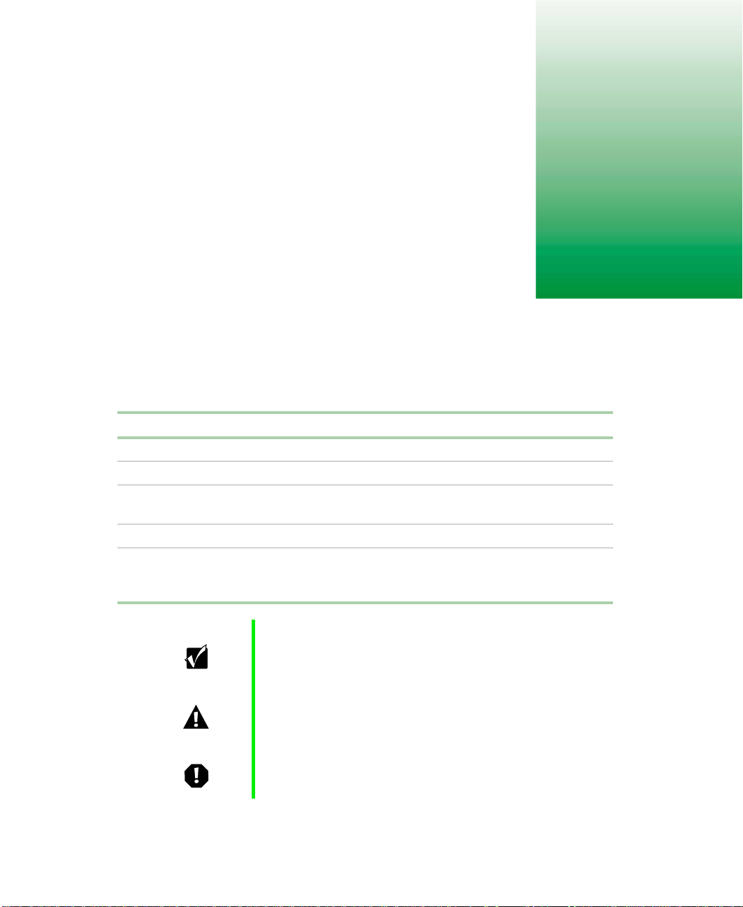
Front bezel
Bezel door provides access to the hot-swap drives and removable media
drives.
Front panel controls provide buttons for power, reset, and sleep, and
indicator lights for system fault, network activity, hard drive access, and
power. For more information on the controls, see “Front panel board” on
page 16.
Bezel door Front panel controls
8 System Features
Page 10
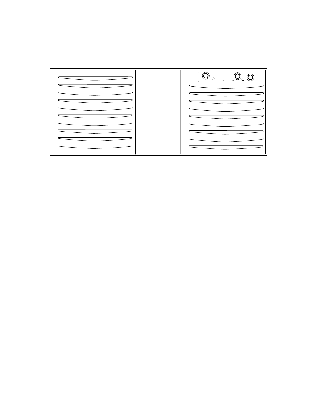
Front panel
5.25-inch drive bayPower supply
Power supply
modules
Power supply supports as many as three hot-swap power supply modules.
5.25-inch drive bay supports one half-height 5.25-inch device.
Control panel contains the light emitting diode (LED) indicators and the
power, reset, and sleep buttons that control the server. For more information
on the controls, see “Front panel board” on page 16.
Hot-swap drive bay includes up to five hot-swappable drives connected to
a hot-swap backplane. The drive bays support 1.0-inch drives.
Slimline
CD drive
Hot-swap drive bay
Slimline
diskette drive
Control panel
Hot-swap drives
Hot-swap drives plug into the hot-swap drive bay.
Slimline diskette drive writes to and reads from 3.5-inch, 1.44 MB diskettes.
Slimline CD drive plays data or audio CDs.
Power supply modules provide N+1 redundant power (if all three modules
are installed).
Front panel 9
Page 11
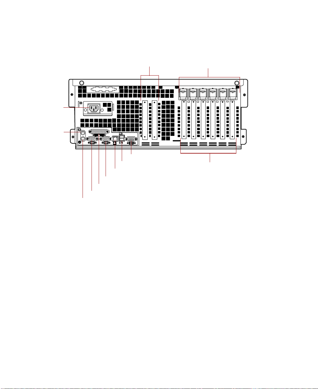
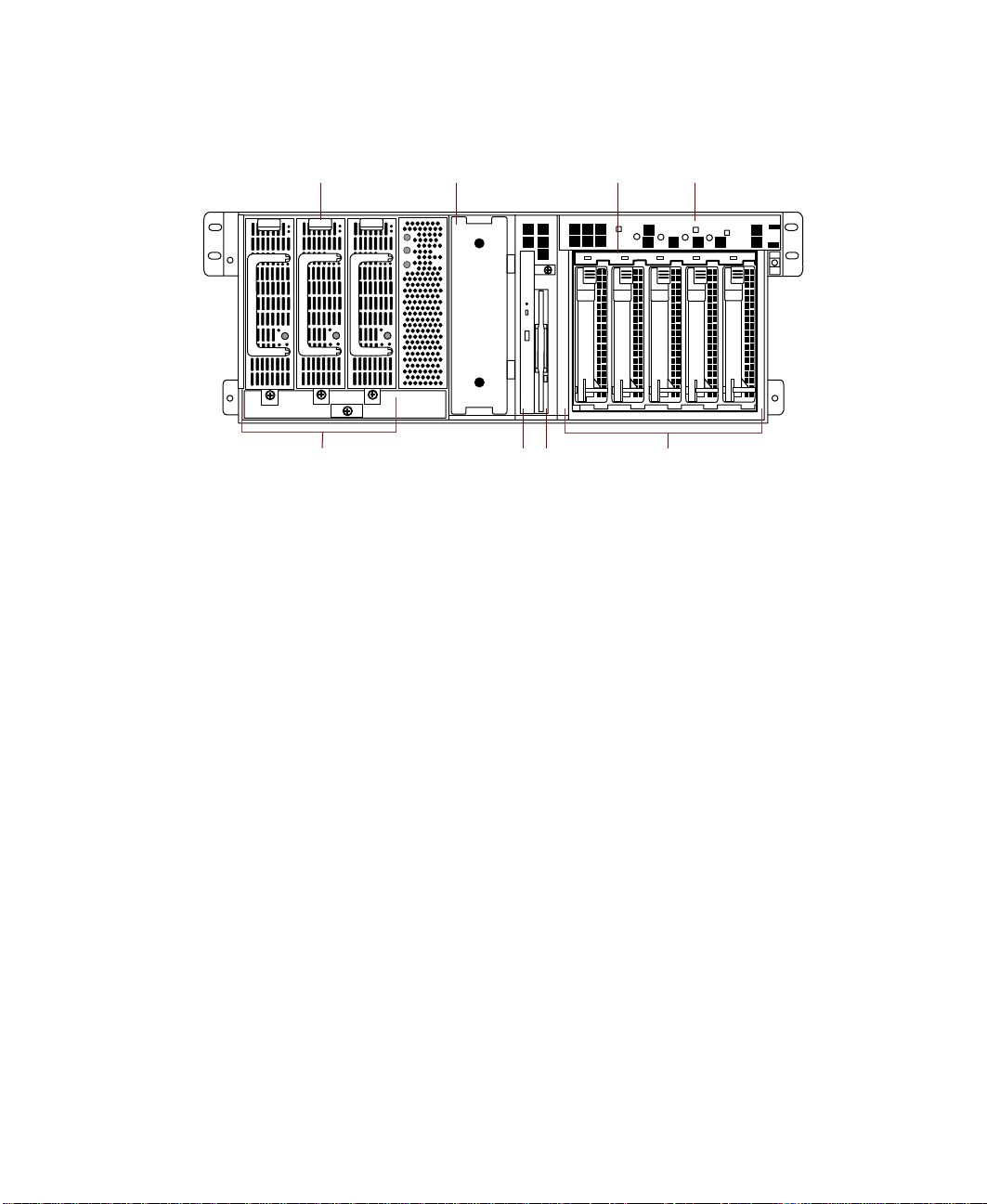
Back panel
Power
connector
PARALLEL
Mouse
port
MOUSE
COM1
KEYBD
Parallel port
Serial port A
Keyboard port
USB 1
NETWORK
COM2
ACT/
LINK
VIEDO
10/100
USB 2
MB
LAN
Video port
USB ports
Network port
Serial port B
Expansion card slots
Hot-plug expansion
card retention clips
Hot-plug expansion
card slots
Expansion card slots (2) let you install as many as two 32-bit, 33 MHz PCI
expansion cards.
Hot-plug expansion card retention clips provide toolless installation of
hot-plug PCI cards.
Hot-plug expansion card slots (6) let you install as many as two 64-bit,
66 MHz hot-plug PCI expansion cards and as many as four 64-bit, 33 MHz
hot-plug PCI expansion cards.
Video por t connects the first (or only) monitor interface cable. The video
controller is integrated in the system board.
USB ports connect external Plug-and-Play devices, such as printers, that are
automatically configured when they are plugged into the server through one
of these ports. USB keyboards and mice are not supported.
Network port lets you connect to a network. The adjacent indicator LEDs
show LAN activity (yellow) and 100 Mbit speed (green).
10 System Features
Page 12
Serial ports (2) connect to serial devices.
Parallel port connects a printer or other parallel device.
Keyboard port connects a PS/2-compatible keyboard.
Mouse port connects a PS/2-compatible mouse.
Power connector connects the server power cord. The other end of the power
cord plugs into an AC outlet or power strip.
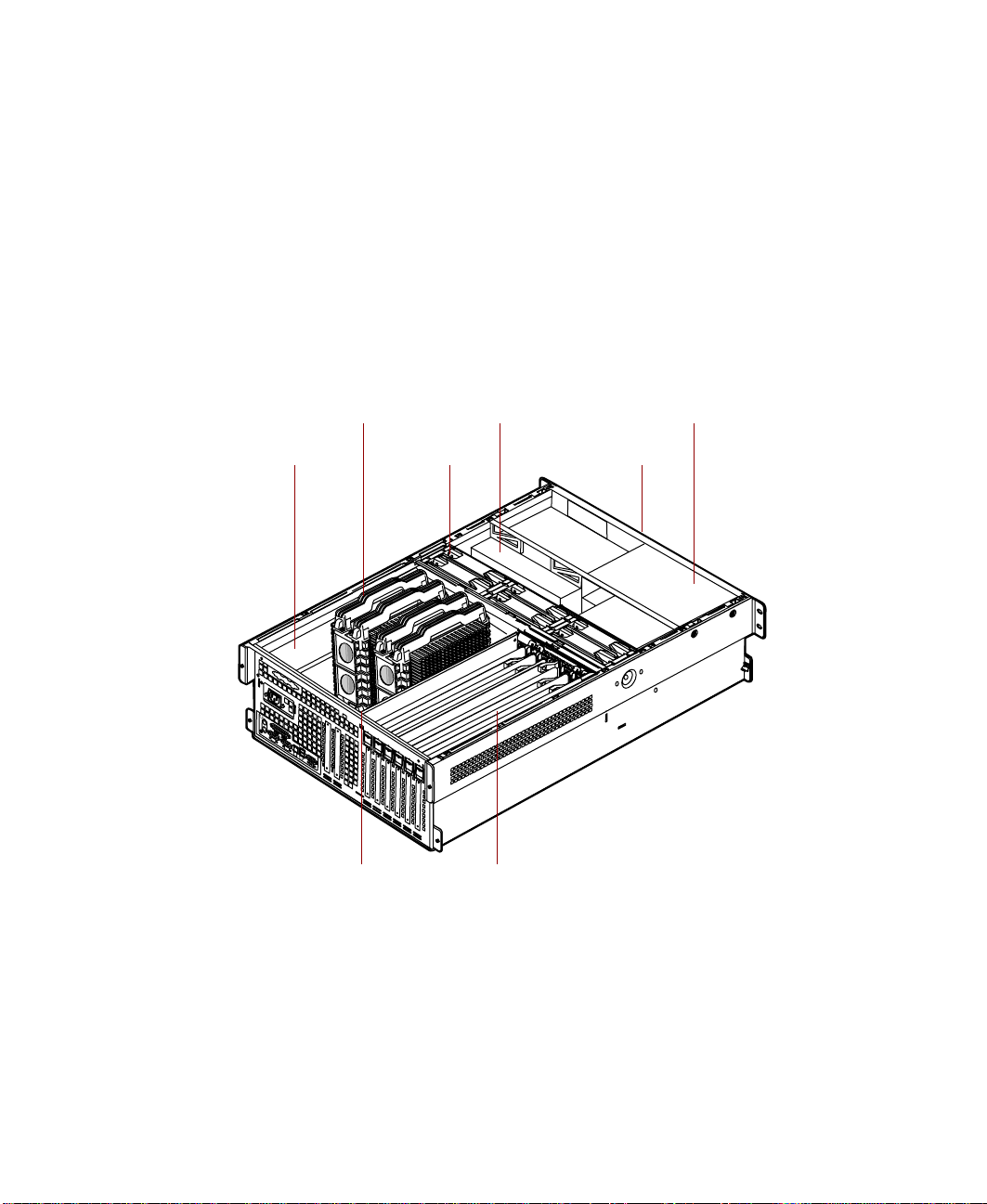
System interior
Processors
Electronics bay
(removed for clarity)
Electronics bay contains the system board, the processors, the memory, and
the expansion cards.
Hot-swap drive bay
Fans
Hot-swap PCI curtainsMemory card
Power supply
Removable media
drives (not visible)
As many as four processors provide the processing power for the server.
System interior 11
Page 13

Fans provide cooling for all server components. There are as many as six
hot-swap fans in the server.
Hot-swap drive bays support up to five 1-inch high 3.25-inch single
connector attachment (SCA) SCSI hard drives. Empty drive bays contain
empty carriers to control airflow and electro-magnetic carrier (EMC)
emissions.
Removable media drives provide transportable storage for data. The server
supports one slimline CD drive, one slimline diskette drive, and one 5.25-inch
drive bay.
Power supply provides N+1 redundant power to the server components.
Hot-plug PCI curtains provide protection from electro-static discharge (ESD)
when installing or replacing hot-plug PCI cards. As many as four 64-bit,
33 MHz cards and as many as two 64-bit, 66 MHz PCI cards can be installed
between these curtains.
Memory card provides sixteen DIMM sockets and supports up to 16 GB of
SDRAM.
12 System Features
Page 14
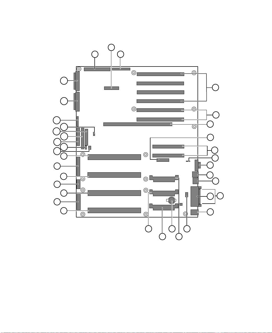
System board
A
AJ
AI
AH
AG
AF
AE
AD
AC
AB
AA
Z
B
C
D
E
F
G
H
I
J
Y
X
W
V
U
R
T
S
P
Q
K
L
N
M
O
A Legacy narrow SCSI connector
B Server monitor module (SMM) feature connector
C Legacy wide SCSI connector
D 64-bit, 33 MHz hot-plug PCI expansion connectors
E 64-bit, 66 MHz hot-plug PCI expansion connectors
F Memory module connector
System board 13
Page 15

G Hot-plug indicator board connector
H 32-bit, 33 MHz half-length PCI expansion connectors
I Intelligent chassis management bus (ICMB) connector
J Video connector
K USB connectors (2)
L RJ-45 Ethernet LAN connector and LEDs
M Parallel port
N Serial ports
O Stacked keyboard and mouse ports
P Internal USB connectors
Q Voltage regulator module (VRM) socket (processor 2)
R Battery
S VRM socket (processor 4)
T VRM socket (processor 3)
U Processor 4 connector
V Main ATX power 1 connector
W Processor 3 connector
X ATX auxiliary power connector
Y Processor 2 connector
Z Main ATX power 2 connector
AA Processor 1 connector
AB Hard drive activity connector
AC SMBus (system management bus) connector
AD Diskette drive connector
AE Integrated drive electronics (IDE) connector
AF Front panel connector
AG Intra Module Bus (IMB) connector
AH Configuration jumper J9F2 (pins 1-3: CMOS Clear, pins 5-7:
Password Clear, pins 9-11: Boot Option)
AI Ultra 160 SCSI A connector
AJ Ultra 160 SCSI B connector
14 System Features
Page 16
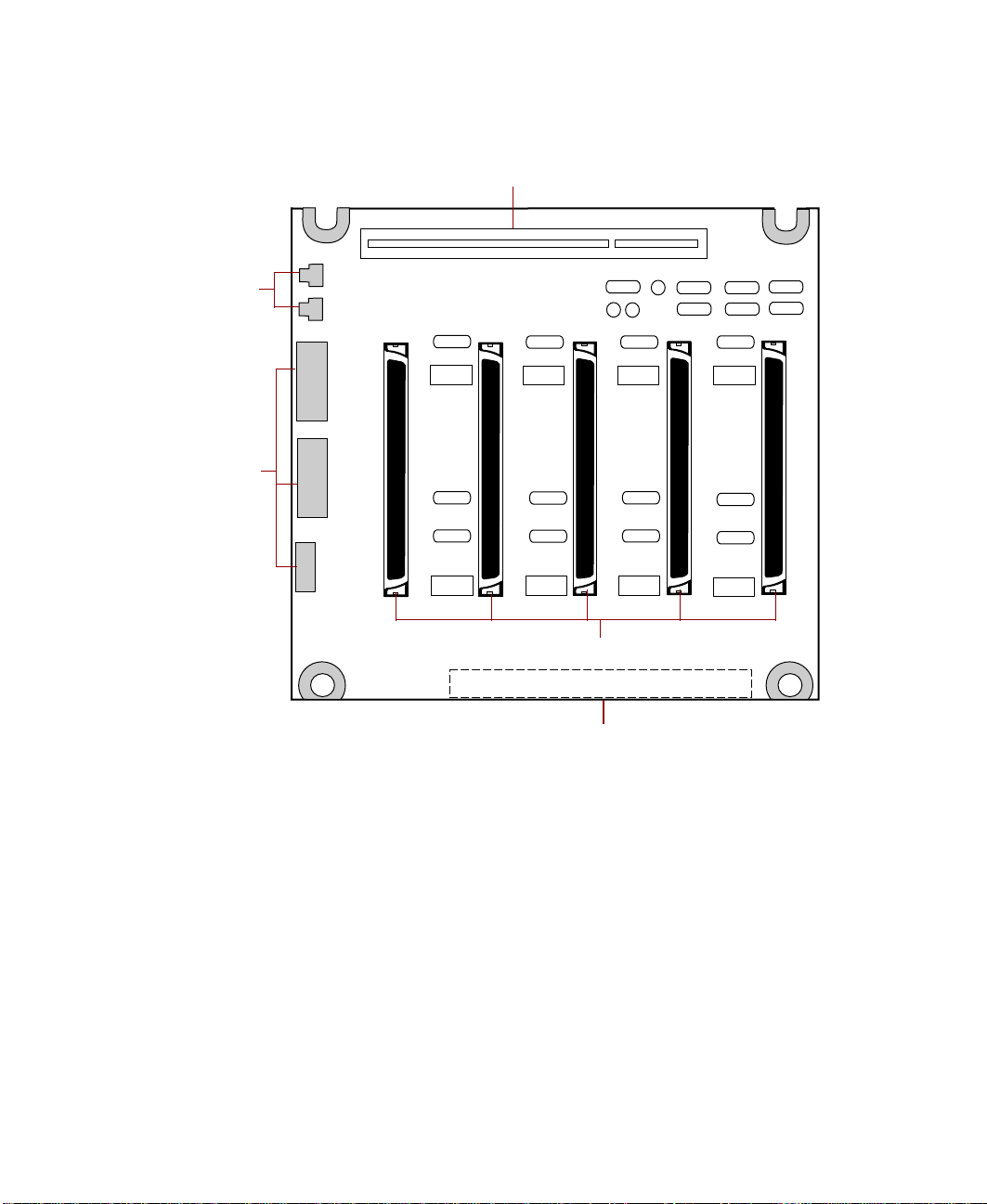
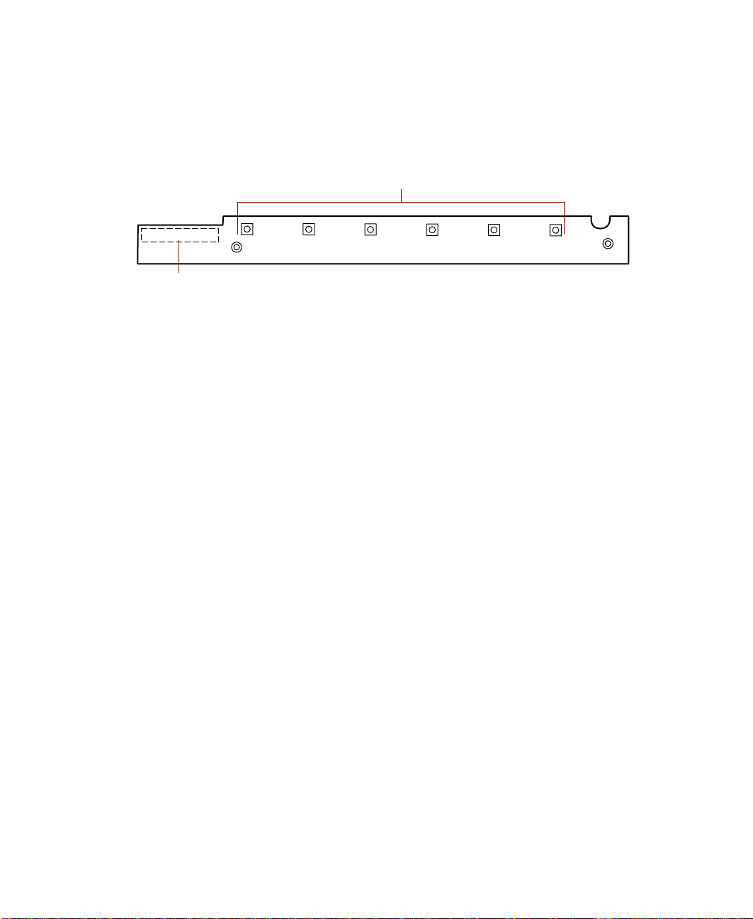
Hot-swap backplane
Hot-swap SCSI indicator board connector
Fan
connectors
Power
connectors
SCSI
ID 4
SCSI
ID 3
SCSI
ID 2
SCSI drive connectors (5)
SCSI data connector
SCSI
ID 1
SCSI
ID 0
Hot-swap SCSI indicator board connector connects the hot-swap indicator
board to the hot-swap backplane.
SCSI drive connectors (5) connect the five SCSI drives. Install drives in
increasing order of SCSI ID.
SCSI data connector connects the SCSI cable from the redundant array of
inexpensive drives (RAID) controller.
Power connectors connect the power cables from the power supply.
Fan connectors connect to dedicated fans for the hot-swap drive bay (not
used).
Hot-swap backplane 15
Page 17
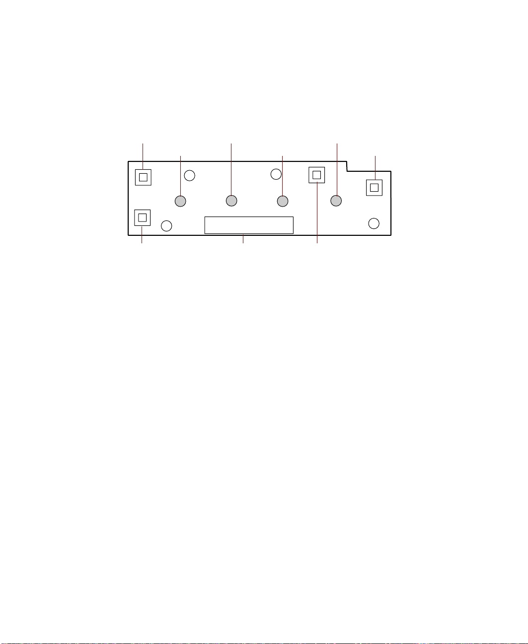
Front panel board
The front panel board supports the LEDs and buttons accessible from the front
panel. The buttons and LEDs on the front panel board are shown and
described below.
Network activity LED Power LEDReset button
System fault LED
Hard drive activity LED Sleep button
NMI switch
Reset button lets you reset the server if it has become nonresponsive.
system fault LED flashes whenever the server logs a failure.
Network activity LED lights whenever there is activity on the network.
Hard drive activity LED glows green whenever a hard drive is actively reading
or writing data and glows amber if a drive fails.
Power LED glows green whenever the server is turned on. The LED also flashes
when the server is in sleep mode.
Sleep button lets you put the server into sleep mode to reduce power
consumption.
Power button turns the server on and off.
Front panel connector connects the controls on the front panel with the
system board.
NMI switch allows a technician servicing the server to generate a
non-maskable interrupt (NMI) to help debug server errors.
Front panel connector Power button
16 System Features
Page 18
Hot-plug PCI indicator board
The hot-plug PCI indicator board provides two LEDs per hot-plug PCI slot to
indicate the status of the board plugged into the slot.
Indicator LEDs
Data cable connector
Indicator LEDs indicate whether the hot-plug PCI slot is active or if it is safe
to replace the board in the indicated slot.
Data cable connector connects to the system board and carries the data
indicating which slots are active.
Hot-plug PCI indicator board 17
Page 19

18 System Features
Page 20

System Setup
Settinguptheserver
Use the instructions on the quick guide poster that came with the server to
assemble the server.
You can prepare a safer working environment before assembling the server
by following these guidelines:
■ Obtain an adequately rated uninterruptible power supply (UPS). A UPS
protects against AC line spikes, power interruptions, and other power
fluctuations that may damage the server.
■ Protect the server from extreme temperature and humidity. Do not
expose it to direct sunlight, heater ducts, or other heat-generating objects.
■ Keep the server away from equipment that generates magnetic fields,
such as unshielded stereo speakers. Even a telephone placed too close to
the server may cause interference.
■ Plug the server into a wall outlet, power strip, or UPS.
Important Keep the boxes and packing material. If you need to send
theserver to Gateway forrepairs, you must use the original
packaging or your warranty may be voided.
2
Settinguptheserver 19
Page 21

Starting the server
Before you start the server for the first time, make sure:
■ The voltage selection switch is in the proper position. If the power supply
is autosensing, it will not have a voltage selection switch and it
automatically determines the voltage of the incoming power source.
■ All cables are firmly connected to the proper ports on the back panel of
the server.
Caution Electricity can flow from connected peripherals i nto the
server causing a shock. Make sure the server and
peripherals are turned off and unplugged from the power
outlet when you connect peripherals to the server.
■ The server and monitor are plugged into an AC outlet, power strip, or
UPS and that the power strip or UPS is turned on.
To start the server:
1 If you have connected the system components to a power strip or UPS,
make sure all the system components are turned off, then turn on the
power strip or UPS.
2 Turn on the monitor.
3 Turn on the server. The LED on the control panel is lit when the power
is on.
4 Tu rn on any other components connected to the server, such as speakers,
a printer, or a scanner.
If nothing happens when you turn on the server:
■ Make sure that the power cables are securely plugged in and that
the power strip or UPS (if you are using one) is plugged in and
turned on.
■ Make sure the monitor is connected to the server, plugged into the
power strip, AC outlet, or UPS, and turned on. You may also need
to adjust the brightness and contrast controls on the monitor.
20 System Setup
Page 22

Understanding the Power-On Self-Test
When you turn on your server, the power-on self-test (POST) routine checks
the server memory and components. To see this information on the screen,
press E
The server displays an error message if POST finds any problems. Write down
any error messages that you see. If you continue to have problems, these error
messages may help you or Gateway technical support diagnose the cause.
SC during POST . Press SPACEBAR to bypass the remaining memory count.
Setting up the operating system
The first time you start the server, the operating system takes a few minutes
to set up.
Refer to your operating system documentation for specific questions regarding
the operating system.
To complete the operating system setup:
1 After the server starts, the start-up wizard opens. Click Next.
2 Type the requested information in the appropriate text boxes. When you
have finished typing the information, click
3 Continue following the instructions and selecting options in the start-up
wizard dialog boxes, clicking
the wizard tells you to restart your server.
Next to move through the dialog boxes, until
Next.
If you need to return to the previous dialog box to change any of your
entries, click
Back.
4 Restart the server. The setup is complete.
Important For all operating systems, refer to the appropriate
operating system softwaremanual for specific instructions.
Starting the server 21
Page 23
Turning off the server
Every time you turn off the server, shut down the operating system first. You
may lose data if you do not follow the proper procedure.
To turn off the server in Windows NT:
1 Click Start, then select Shut down the computer?, then click Shut Down.
2 Click OK. The operating system shuts down. When you see a message
saying
the power button.
3 Turn off the monitor and peripherals.
Important For other operating systems, such as Windows 2000 or
It is nowsafe to turn off yourcomputer, turn off the server by pressing
Caution When you turn the server off, some electric current still
flows through it. Before opening the server case or
connectingorremovinganyperipherals,turn off the server,
then unplug the power cord.
Novell Netware, refer to the appropriate operating system
software manual for specific instructions.
22 System Setup
Page 24

Resetting the server
If your server does not respond to keyboard or mouse input, you may have
to close programs that are not responding. If closing unresponsive programs
does not restore your server to normal operation, you may have to reset the
server.
To close unresponsive programs and reset the server in Windows NT:
1 Press CTRL+ALT+DEL. A window opens that lets you close a program that
is not responding.
2 Click Task Manager, then select the program that is not responding.
3 Close the program by clicking End Task.
4 If the server does not respond, press the reset button to restart the server.
As a part of the regular startup process, a program to check the disk status
runs automatically. When the checks are finished, Windows starts.
Important For other operating systems, such as Windows 2000 or
Novell Netware, refer to the appropriate operating system
software manual for specific instructions.
Resetting the server 23
Page 25

24 System Setup
Page 26

Case Access
3
Preventing static electricity discharge
Before opening the server case, follow these precautions to prevent damage
from static electricity. When opening your server case, always perform the
following procedure.
Caution Static electricity can permanently damage electronic
components in your server. Prevent electrostatic damage
to your server by following static electricity precautions
every time you open your server case.
To prevent static electricity discharge:
1 Turn off the server.
2 Touch a bare metal surface on the back of the server.
3 Unplug all power cords from AC outlets and disconnect the modem cable
(if installed).
Also follow these static electricity precautions:
■ Avoid static-causing surfaces such as plastic and packing foam in your
work area.
■ Remove the parts from their antistatic bags or containers only when you
are ready to use them. Do not lay parts on the outside of an antistatic
bag or container because only the inside provides antistatic protection.
■ Always hold cards by the edges and their metal mounting brackets. Avoid
touching components on the cards and the edge connectors that connect
to expansion slots. Never slide cards or other parts over any surface.
Preventing static electricity discharge 25
Page 27

Opening the case
Important All references to front, back, left, or right on the server are
based on the server being in a normal, upright position,
as viewed from the front.
The only components that are accessible from the outside of the chassis are
the front panel controls and indicator lights, the hot-swap power supply
modules, the slimline diskette and CD drives, and the hot-swap hard drives.
T o access the hot-swap drives, the removable media drives, or the front panel
you must open the bezel. To work on the internal components of the server,
you must open the chassis.
Because the components inside the server are extremely sensitive to static
electricity, make sure you follow the precautions at the beginning of this
chapter to avoid static electricity damage.
Only qualified personnel should open the server for maintenance. If you are
qualified to maintain the server yourself, make sure you are properly grounded
before opening the server chassis.
Caution Avoid exposure to dangerous electrical voltages and
movingparts byturning off yourserverand unplugging the
powercord andmodem cable(if installed) beforeremoving
the chassis cover.
26 Case Access
Page 28
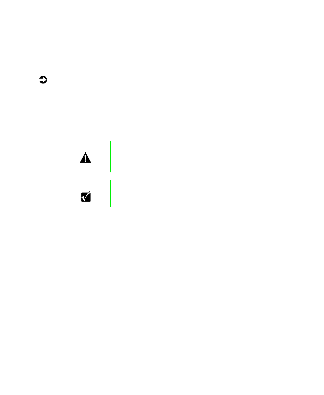
Opening the bezel door
The bezel door covers the removable media drives, the hot-swap drives, and
the front panel controls. To access these components, you must open the
bezel.
To open the bezel door:
1 Grip the bezel door and pull the door straight out away from the chassis.
2 Swing the door outward to the right.
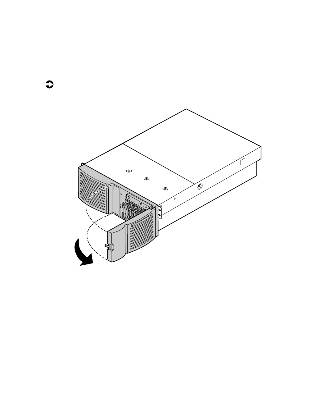
Removing the bezel
The bezel covers the hot-swap power supply modules and the fasteners for
the removable media drives. You must remove the bezel to swap a power
supply module or replace a removable media device.
Opening the case 27
Page 29
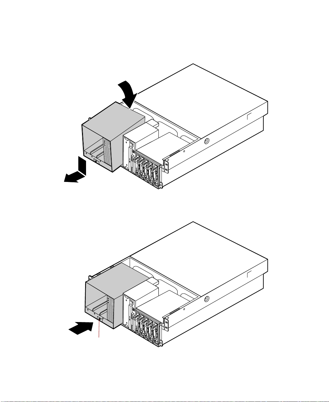
To remove the bezel:
1 Grip the bezel at both sides and pull it straight out from the front panel.
Removing the back top panel
The back top panel provides access to the hot-swap fans, the hot-swap PCI
slots, the memory card, the processors and VRMs, and the standard PCI slots.
To remove the back top panel:
1 Observe all safety and static electricity precautions, see “Preventing static
electricity discharge” on page 25.
Important You do not have to turn off the server to open the back
top panel.However, do not removethe EMI foam from the
electronics bay unless you have turned the server off and
unplugged the power cord.
28 Case Access
Page 30
2
Thumbscrew
Thumbscrew
3 Slide the top panel slightly to the back, disengaging the front edge of
4 Lift the panel out and away from the chassis.
Loosen the two thumbscrews from the top edge of the back panel.
the panel from the front top panel.
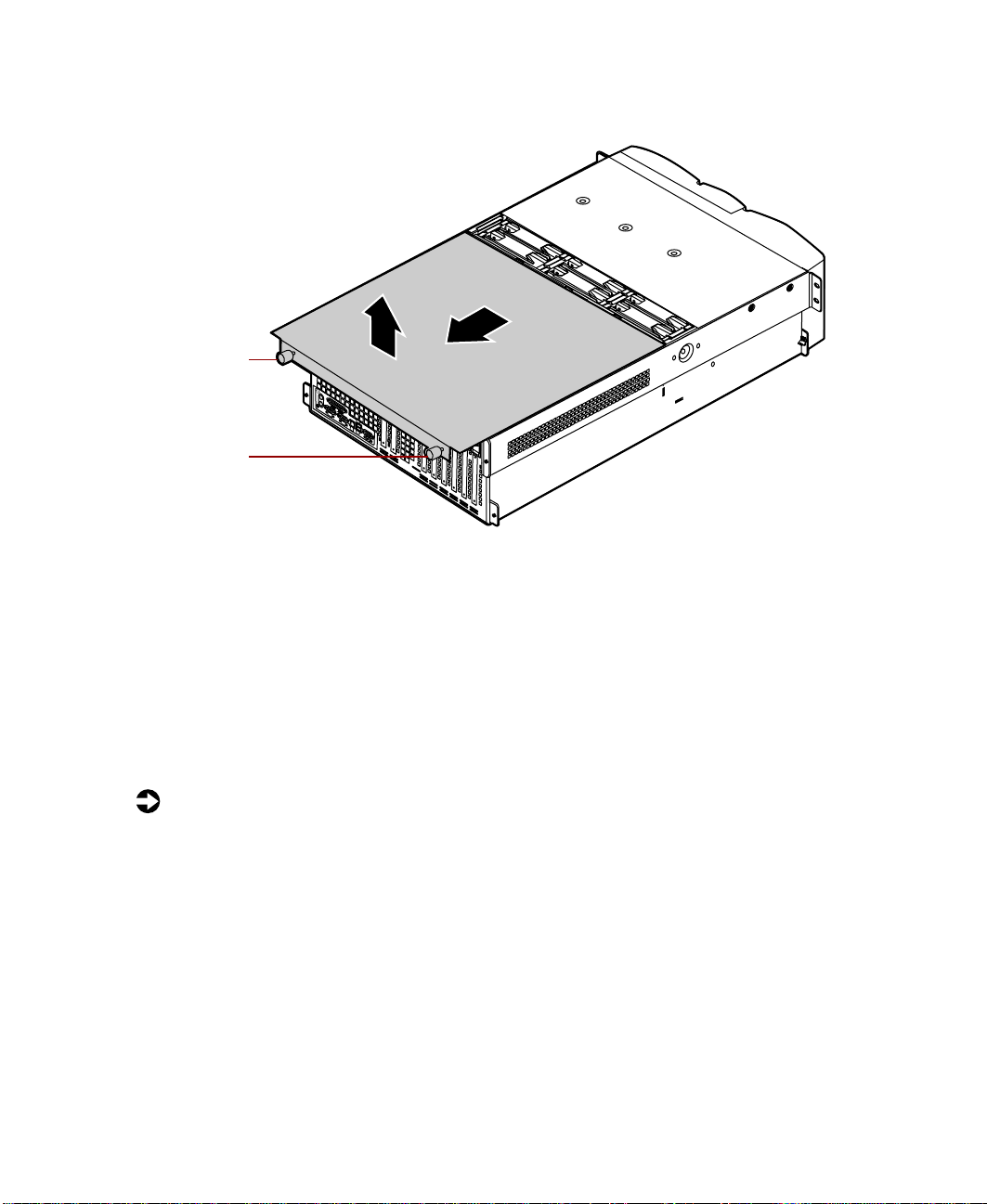
Removing the front top panel
The front top panel provides access to the hot-swap drive cage, the drive
cables, the power supply cables, and the front panel board.
To remove the front top panel:
1 Turn off the server and disconnect all power cords.
2 Observe all safety and static electricity precautions, see “Preventing static
electricity discharge” on page 25.
Opening the case 29
Page 31

3 Remove the three screws from the top of the front top panel.
4 Slide the top panel slightly to the front, disengaging the back edge of
the panel from the top of the front panel.
5 Lift the panel out and away from the chassis.
30 Case Access
Page 32
Closing the case
Close the chassis as soon as you finish installing or removing components
so that dust and dirt do not collect inside the server.
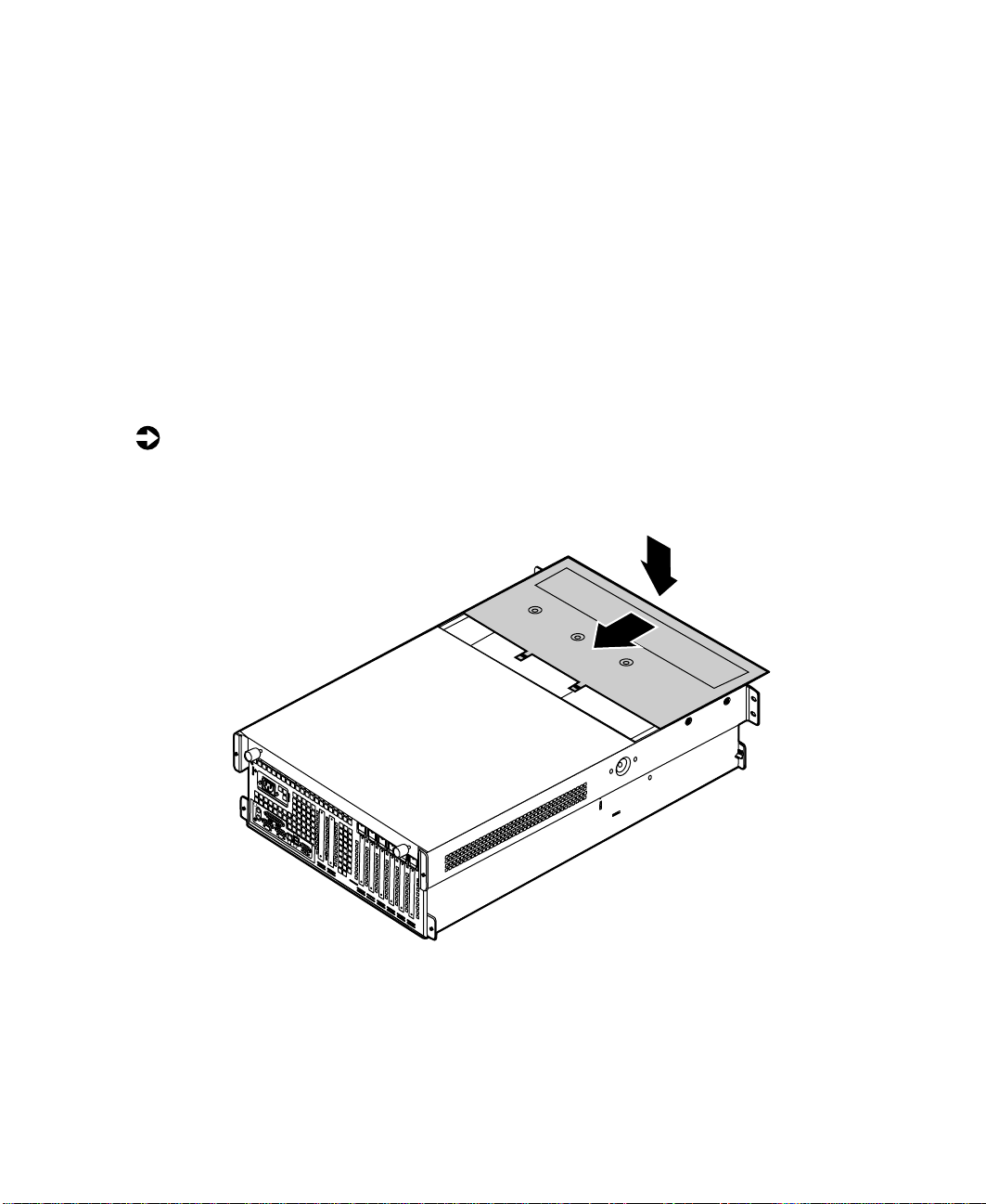
Replacing the fronttop panel
You can replace the front top panel whether the back top panel is on or off
of the chassis. You must replace the front top panel before you can operate
the server. If you do not, a system intrusion event is logged by the system
management hardware. Be careful not to pinch any cables with the panel as
you replace it.
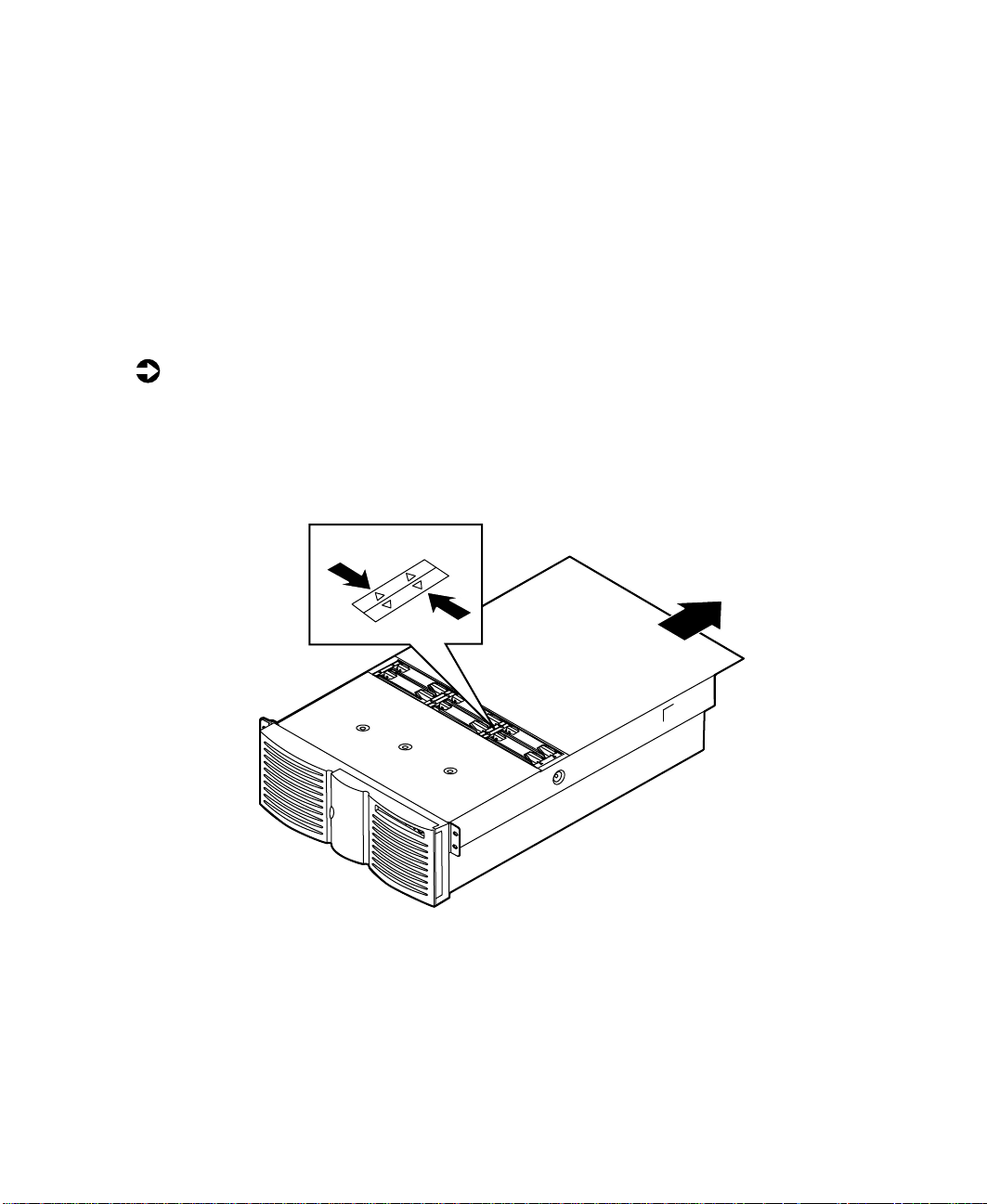
To replace the front top panel:
1 Place the front top panel on the top of the chassis approximately 3/4-inch
forward from the front of the server.
Closing the case 31
Page 33

2 Slide the panel toward the back of the chassis, securing it in place. The
tabs on the back edge of the front top panel slide under the lip of the
back top panel.
3 Replace the screws you removed earlier.
32 Case Access
Page 34

Replacing the backtop panel
To replace the back top panel:
1 Place the back top panel on the top of the chassis approximately 3/4-inch
back from the back edge of the front top panel.
2 Slide the panel toward the front of the chassis, securing it in place. Be
careful not to pinch any cables with the panel as you replace it.
3 Tighten the thumbscrews you loosened earlier.
Closing the case 33
Page 35

Replacing the bezel
The bezel prevents unauthorized access to the hot-swap power supply modules
and the fasteners for the removable media drives.
To replace the bezel:
1 Align the four pins on the back of the bezel with the four holes in the
sides of the front panel and press the bezel firmly into place.
34 Case Access
Page 36

Replacing and Adding Internal Devices
Drives
There are several types of drives and similar devices that can be installed in
the server.
Preparing to replace or adda drive
One 3.5-inch diskette drive, at least one 1-inch high 3.5-inch hot-swap hard
drive, and one slimline CD drive are included with the server. You can add
up to four additional 3.5-inch hot-swap drives for a total of five hot-swap
drives. You may also add one 5.25-inch device.
As you prepare to install drives, keep the following in mind:
■ If you remove a drive, place it in an antistatic bag or container.
■ Before you install a drive, see the drive documentation for information
on configuring the drive, setting any jumpers on the drive, and attaching
cables to the drive.
4
■ If you are installing a drive that uses an add-in controller, install the
expansion card before you install the drive.
■ You may need to configure the drives you install using the BIOS (Basic
Input/Output System) Setup utility or the SCSISelect utility. Press F2 at
start up to open the BIOS Setup utility or press C
SCSISelect utility.
TRL+A to enter the
Drives 35
Page 37

Drive cabling information
The server includes four different types of drive cables. Each drive cable is
clearly labeled, indicating the cable type and showing which end to connect
to the appropriate connector on the system board and which end to connect
to the drive.
■ Use the diskette drive connector cable to connect the diskette drive.
■ Use the standard IDE connector cable to connect the CD drive and an
IDE device installed in the 5.25-inch drive bay to the system board.
■ Use a narrow SCSI cable to connect a legacy narrow SCSI device in the
5.25-inch drive bay to the legacy narrow SCSI controller integrated onto
the system board
■ Use the SCSI low-voltage differential (LVD) cable to connect the hot-swap
backplane to the integrated SCSI controller on the system board.
Removing a hot-swap drive
The hot-swap drives are located at right side of the front panel. The hot-swap
drive bay supports as many as five, 1-inch high 3.5-inch SCSI hard drives.
The hot-swap drives are assigned SCSI ID numbers by the hot-swap backplane
with the drive on the right end of the hot-swap bay assigned SCSI ID 0. The
backplane assigns SCSI IDs to the other drives in order up to SCSI ID 4 on
the left end of the hot-swap bay. See “Hot-swap backplane” on page 15 for
the locations of the drives by SCSI ID number.
Important Gatewaytests and verifies the operation and compatibility
ofthe drives we sell. Additionalor replacementdrivesmust
conform to Gateway standards, especially in a RAID or
mission-critical environment.
Install the first drive at the right end, then install drives in increasing order
by SCSI ID number thereafter. You do not need to turn off the server before
you remove or replace a hot-swap drive.
36 Replacing and Adding Internal Devices
Page 38

To remove a hot-swap drive:
1 Follow the static electricity precautions in “Preventing static electricity
discharge” on page 25.
2 Use the SCSI control software to stop activity on the drive you need to
remove.
3 Open the bezel door as described in “Opening the bezel door” on page 27.
4 Pinch the grip of the drive carrier handle to release the clip at the top.
5 Swing the carrier handle down and pull the drive out of the drive cage.
Continue pulling until the drive is entirely out of the drive cage.
6 Place the drive on a static-free surface. If you are replacing the drive, see
“Installing a hot-swap drive” on page 38.
Drives 37
Page 39

Installing a hot-swap drive
If you are adding a drive to an empty drive slot, you must first remove the
air baffles from the drive carrier . If you are replacing an existing drive, remove
the old drive as described in “Removing a hot-swap drive” on page 36.
To install a hot-swap drive:
1 Follow the static electricity precautions in “Preventing static electricity
discharge” on page 25.
2 Remove the drive carrier as described in “Removing a hot-swap drive”
on page 36.
3 Remove the four screws that secure the air baffles to the drive carrier. If
you are removing an existing drive, the same four screws secure the old
drive to the carrier.
38 Replacing and Adding Internal Devices
Page 40

Use the four screws you removed in Step 3 to secure the new drive to
4
the drive carrier.
5 With the drive carrier handle in the open position, align the drive carrier
rails with the grooves at the top and bottom of the drive bay.
6 Slide the drive into the bay until the handle starts to close. Make sure
the tab on the bottom of the handle fits into the slot on the bottom of
the drive cage.
Tab
Slot
7 Close the handle securely to set the drive connector into the connector
at the back of the drive cage.
8 Close the bezel door.
9 Use the SCSI control utility to format and configure the new drive.
Drives 39
Page 41

Replacing the hot-swapbackplane
The hot-swap drive bay indicator board comes out of the server with the
hot-swap backplane. This procedure removes both boards from the sever.
You should only replace the hot-swap backplane if Gateway Client Care has
instructed you to do so. The hot-swap drive cage fits very tightly in the chassis
and you may need the assistance of a second technician to remove it.
To replace the hot-swap backplane:
1 Follow the static electricity precautions in “Preventing static electricity
discharge” on page 25.
2 Tu rn off the server and disconnect the power cord and all other external
peripheral devices.
3 Remove the front top panel as described in “Removing the front top
panel” on page 29.
4 Disconnect all cables from the drive cage and the backplane.
5 Remove all of the hot-swap drive carriers from the hot-swap drive cage
as described in “Removing a hot-swap drive” on page 36.
6 Using a flat-bladed screwdriver or similar tool, press the plastic tabs on
both sides of the drive cage toward the center of the cage. You may need
to hold them in on one side while pressing them in on the other.
40 Replacing and Adding Internal Devices
Page 42

When you have freed all four tabs, push the drive cage out from the back,
7
then pull it out of the chassis.
Drives 41
Page 43

8 Remove the four screws that secure the hot-swap backplane to the
hot-swap drive cage, then pull the backplane out of the drive cage. The
hot-swap indicator board will also come out of the drive cage.
9 Remove the hot-swap indicator board and the plastic shield from the
hot-swap backplane and place both boards on a static-free surface.
42 Replacing and Adding Internal Devices
Page 44
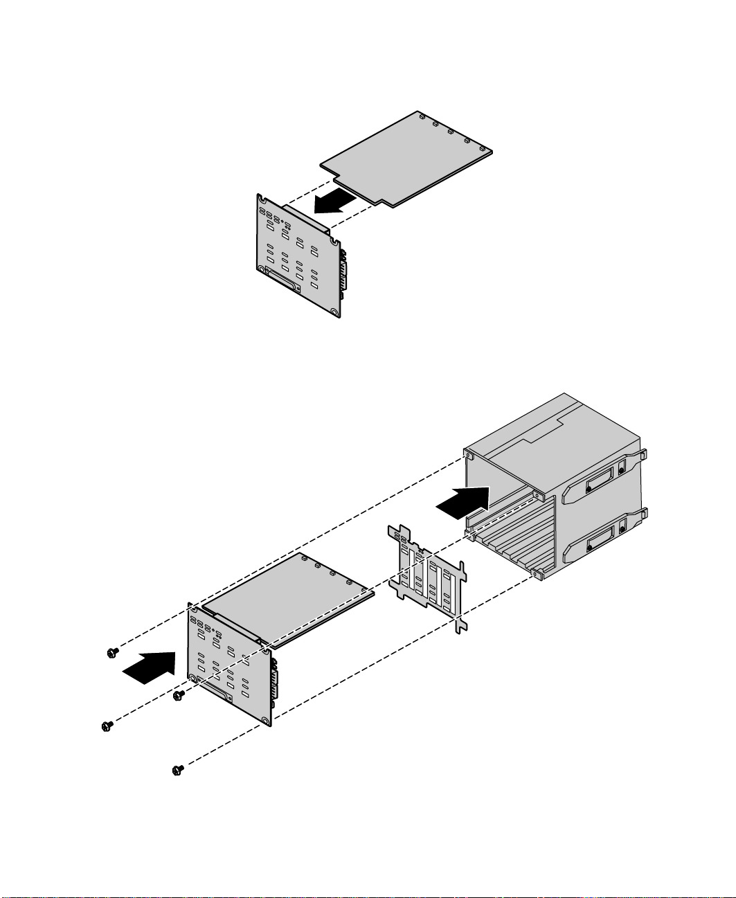
Plug the hot-swap indicator board into the new hot-swap backplane.
10
11 Put the plastic shield into place and carefully insert the two boards into
the hot-swap drive cage
Drives 43
Page 45

12 Secure the hot-swap backplane in placed with the four screws you
removed in Step 8.
13 Align the four rails on the sides of the drive cage with the grooves in
the chassis and slide the hot-swap drive cage back into the chassis.
14 Install all of the hot-swap drive carriers as described in “Installing a
hot-swap drive” on page 38.
15 Reconnect the cables to the hot-swap backplane.
16 Replace the front top panel as described in “Replacing the front top
panel” on page 31.
17 Plug in the peripherals and the power cord and turn on the server.
44 Replacing and Adding Internal Devices
Page 46
Replacing the CD drive and the diskettedrive
The slimline CD drive and the slimline diskette drive are near the center of
the front panel. See “Front panel” on page 9 for the location of the slimline
diskette drive and slimline CD drive.
To replace the slimline CD drive and the slimline diskette drive:
1 Turn off the server and disconnect the power cord and all other external
peripheral devices.
2 Remove the front top panel. (See “Removing the front top panel” on
page 29 and “Preventing static electricity discharge” on page 25.)
3 Remove the power and data cables from the back of the slimline diskette
drive and the slimline CD drive, noting their locations and orientations.
(You will reconnect these cables after you install the new drive.)
4 Remove the diskette drive tray by removing the screw from the front
panel.
5 Pull the tray out of the chassis.
Drives 45
Page 47

6 Pull the top (right) edge of the CD drive free from the clips holding it
in place.
7 Pull the top (right) edge of the diskette drive free from the tray in the
same manner.
8 If necessary, set any jumpers on the new diskette drive. (See your drive
documentation for proper drive jumper settings and cable orientation.)
46 Replacing and Adding Internal Devices
Page 48

Align the holes on the bottom (left) edge of the diskette drive with the
9
pins on the drive tray and press the diskette drive firmly in place.
10 Align the holes on the bottom (left) edge of the CD drive with the pins
on the drive tray and press the CD drive firmly into place.
Drives 47
Page 49

11 Replace the tray in the chassis using the screw you removed in Step 4 to
secure the tray in position.
12 Connect the power and data cables, making sure the cables are in their
original positions.
13 Close the case. (See “Closing the case” on page 31.)
14 Reconnect the power cord and all other external peripheral devices, then
turn on the server.
48 Replacing and Adding Internal Devices
Page 50

Installing a 5.25-inch device
The chassis supports a single half-height 5.25-inch device. The 5.25-inch drive
bay is in the center of the front panel (see “System board” on page 13.)
To install a 5.25-inch device:
1 Turn off the server and disconnect the power cord and all other external
peripheral devices.
2 Remove the bezel. (See “Removing the bezel” on page 27.)
3 Remove the front top panel. (See “Removing the front top panel” on
page 29 and “Preventing static electricity discharge” on page 25.)
4 Pull out the metal electro-magnetic interference (EMI) shield from the
front of the 5.25-inch drive bay and save it in case you need to remove
the 5.25-inch device you are installing.
5 Install the drive rails on the 5.25-inch device. (See the documentation
that came with the device for any jumper settings and cable orientation
information.)
Drives 49
Page 51

6 Align the drive rails with the grooves at the top and bottom of the
5.25-inch drive bay and slide the device into the bay until the rails click
into place.
7 Connect power and data cables to the device, making sure the cables are
oriented correctly.
8 Close the case. (See “Closing the case” on page 31.)
9 Reconnect the power cord and all other external peripheral devices, then
turn on the server.
Replacing a 5.25-inch device
The chassis supports a single half-height 5.25-inch device. The 5.25-inch drive
bay is in the center of the front panel. If you remove a device from the
5.25-inch drive bay, you must either install a replacement device or install
the metal EMI shield that originally shipped with the server.
50 Replacing and Adding Internal Devices
Page 52

To replace a 5.25-inch device:
1 Turn off the server and disconnect the power cord and all other external
peripheral devices.
2 Remove the bezel. (See “Removing the bezel” on page 27.)
3 Remove the front top panel. (See “Removing the front top panel” on
page 29 and “Preventing static electricity discharge” on page 25.)
4 Disconnect the power and data cables from the device. If you intend to
install a replacement device, note the location and orientation of the
cables to make installing the replacement device easier.
5 Pinch the front ends of the drive rails toward the center of the drive bay ,
and pull the drive out of the bay.
Drives 51
Page 53

6 Remove the drive rails from the device by removing the four screws that
hold them in place.
7 If you are installing a replacement device, install the rails on the device
and proceed from Step 5 on page 49.
8 If you are not installing a replacement device, re-install the metal EMI
shield you removed when you originally installed the 5.25-inch device.
9 Close the case. (See “Closing the case” on page 31.)
10 Reconnect the power cord and all other external peripheral devices, then
turn on the server.
Memory
Sixteen DIMM sockets on the separate memory board support up to
16.0 Gigabytes (GB) of PC/100 SDRAM.
Replacing memory
The SDRAM DIMMs supported by your system board conform to the following
standards:
■ 64 MB, 128 MB, 256 MB, 512 MB, and 1 GB Error Checking and
Correcting (ECC) DIMMs
■ PC100-compliant, registered, parity, ECC SDRAM
52 Replacing and Adding Internal Devices
Page 54

When you select and install DIMMs, keep the following in mind:
■ Registered DIMMs should not be combined with unbuffered DIMMs.
■ Memory must be installed in complete banks (four DIMMs at a time),
from bank A to bank D.
■ No jumper settings are required for the memory size or type because the
BIOS automatically detects this information.
■ 16 GB maximum system memory.
Memory banks are arranged as shown in the figure below.
D2
B2
C2
A2
D4
B4
C4
A4
To replace DIMMs:
1 Turn off the server and disconnect the power cord and all other external
peripheral devices.
2 Remove the back top panel. (See “Removing the back top panel” on
page 28 and “Preventing static electricity discharge” on page 25.)
Memory 53
D1
C1
D3
C3
B1
A1
B3
A3
Page 55

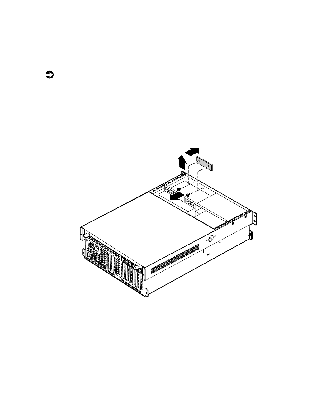
3 Remove the memory board retention bracket by removing the screw at
the back end, sliding the bar to the front, and lifting the bracket out of
the slot on the edge of the electronics bay.
54 Replacing and Adding Internal Devices
Page 56
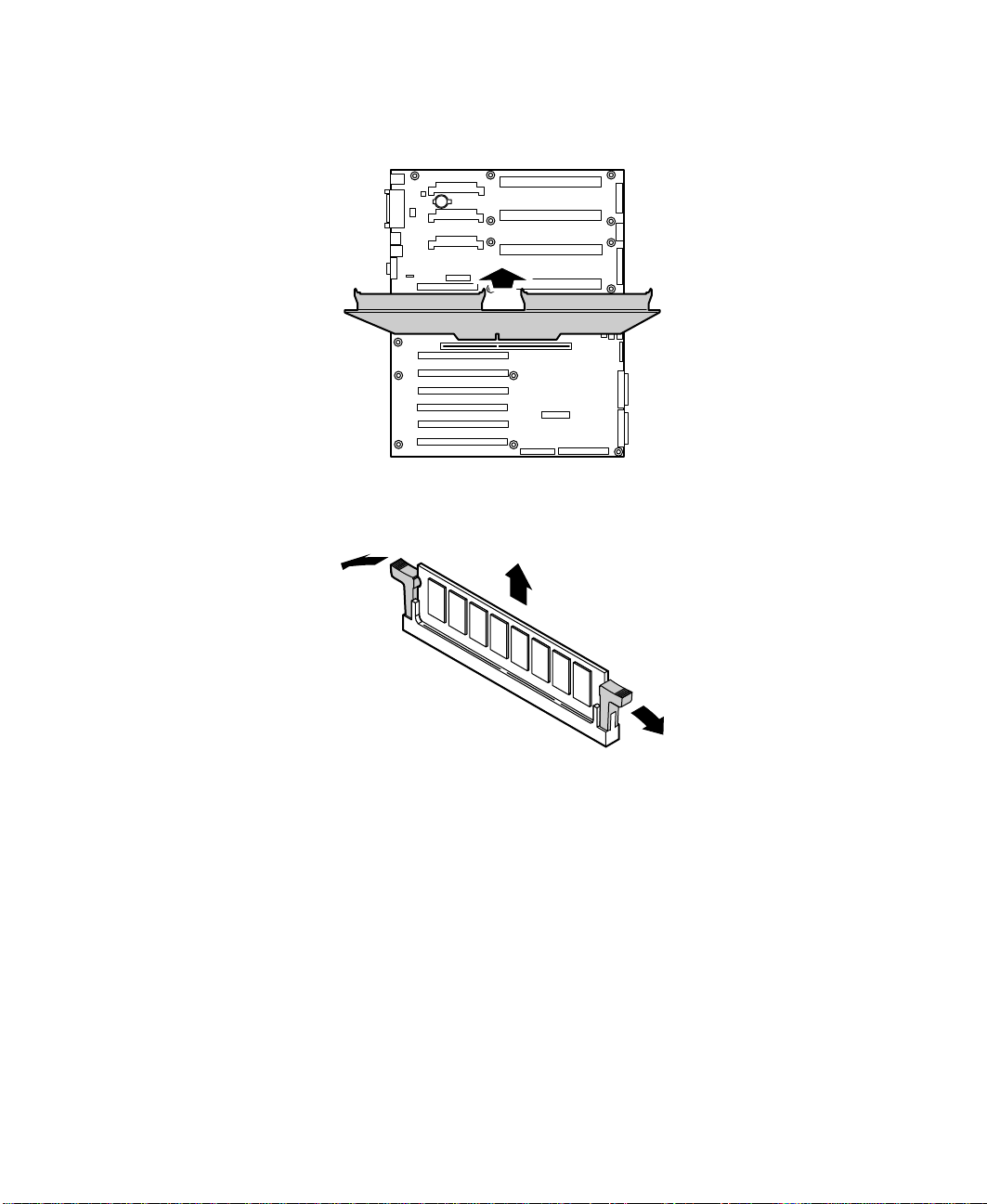
Pull the memory board out of the chassis and place it on a static-free
4
surface.
Boards shown outside
chassis for clarity
5 Pull open the socket clamps on each side of the DIMM socket, then lift
the DIMM out of the socket. Store the DIMM in an anti-static container.
Memory 55
Page 57

6 Insert the new DIMM into the socket, aligning the two notches in the
DIMM with the two notches in the DIMM socket.
7 Gently press the DIMM into the socket until it is firmly seated. Inserting
the DIMM automatically locks the socket clamps on each end of the
DIMM.
8 Once all DIMMs have been installed, replace the memory board in the
server.
56 Replacing and Adding Internal Devices
Page 58

Replace the memory board retention bracket, hooking the tab over the
9
edge of the electronics bay and replacing the screw in the back panel.
10 Close the case. (See “Closing the case” on page 31.)
11 Reconnect the peripherals and the power cord, then turn on the ser ver.
Installing memory
The SDRAM DIMMs supported by your system board conform to the following
standards:
■ 64 MB, 128 MB, 256 MB, 512 MB, and 1 GB ECC DIMMs
■ PC100-compliant, registered, parity, ECC SDRAM
Memory 57
Page 59

When you select and install DIMMs, keep the following in mind:
■ Registered DIMMs should not be combined with unbuffered DIMMs.
■ Memory must be installed in complete banks (four DIMMs at a time),
from bank A to bank D.
■ No jumper settings are required for the memory size or type because the
BIOS automatically detects this information.
■ 16 GB maximum system memory.
Memory banks are arranged as shown in the figure below.
D2
B2
C2
A2
D4
B4
C4
A4
To add DIMMs:
1 Tu rn off the server and disconnect the power cord and all other external
peripheral devices.
2 Remove the back top panel. (See “Removing the back top panel” on
page 28 and “Preventing static electricity discharge” on page 25.)
58 Replacing and Adding Internal Devices
D1
C1
D3
C3
B1
A1
B3
A3
Page 60

Remove the memory board retention bracket by removing the screw at
3
the back end, sliding the bar forward, and lifting the bracket out of the
slot on the edge of the electronics bay.
4 Pull the memory card out of the chassis and put it on a static-free surface.
Boards shown outside
chassis for clarity
Memory 59
Page 61

5 Pull open the socket clamps on each side of the DIMM socket.
6 Insert the new DIMM into the socket, aligning the two notches in the
DIMM with the two notches in the DIMM socket.
7 Gently press the DIMM into the socket until it is firmly seated. Inserting
the DIMM automatically locks the socket clamps on each end of the
DIMM.
8 Once all DIMMs have been installed, replace the memory board in the
server.
60 Replacing and Adding Internal Devices
Page 62

Replace the memory board retention bracket, hooking the tab over the
9
edge of the electronics bay and replacing the screw in the back panel.
10 Close the case. (See “Closing the case” on page 31.)
11 Reconnect the peripherals and the power cord, then turn on the ser ver.
Processors
The server is compatible with the Intel® Pentium®III 550 MHz and faster
processors with 100MHz FSB. As many as four processors may be installed
in the server (they must have the same processor and FSB speed). Processor
and FSB speed are automatically detected by the server. Processors must be
installed in order, from slot 1 through slot 4 and a VRM must be installed
for each processor added to the server. Whenever processors are installed, the
most current version of the BIOS should be installed as well (see “Updating
the BIOS” on page 113).
Processors 61
Page 63

Replacing a processor
When replacing a processor, order a processor upgrade kit from Gateway.
Caution A heatsink must be installed on each processor. Installing
a processor without a heatsink could result in damage to,
or failure of, the processor.
To replace a processor:
1 Turn off the server and disconnect the power cord and all external
peripheral devices.
2 Remove the back top panel. (See “Preventing static electricity discharge”
on page 25 and “Removing the back top panel” on page 28.)
3 Remove the EMI foam cover over the processors.
62 Replacing and Adding Internal Devices
Page 64

Using a phillips screwdriver, remove the two screws that hold the
4
processor retention bracket in place.
5 Pull the processor up and out of the slot.
6 If the heatsink is separate, attach it to the processor.
Processors 63
Page 65

7 Align the new processor with the processor slot (note that the processor
slot is keyed so the processor can only be installed one way) and press
firmly to install it.
8 Replace the processor support bracket using the two screws you removed
in Step 4.
64 Replacing and Adding Internal Devices
Page 66

Replace the EMI foam in the same orientation it was in when you
9
removed it.
10 Close the case. (See “Closing the case” on page 31.)
11 Reconnect the power cord and all other cords you removed, then turn
on the server.
Important Gatewayrecommends that you run a processorretest from
the BIOS Setup utility whenever you replace or add a
processor.
Installing a processor
When replacing a processor, order a processor upgrade kit from Gateway.
Caution A heatsink must be installed on each processor. Installing
a processor without a heatsink could result in damage to,
or failure of, the processor.
Processors 65
Page 67

To add a second (or later) processor:
1 Turn off the server and disconnect the power cord and all external
peripheral devices.
2 Remove the back top panel. (See “Preventing static electricity discharge”
on page 25 and “Removing the back top panel” on page 28.)
3 Remove the EMI foam cover over the processors.
66 Replacing and Adding Internal Devices
Page 68
Using a phillips screwdriver, remove the two screws that secure the
4
processor retention bracket, then remove the terminator card from the
processor slot you want to install the new processor in.
5 If the heatsink is separate, attach it to the new processor.
Processors 67
Page 69

6 Align the new processor with the processor slot. Note that the processor
slot is keyed so the processor can only be installed one way . Press it firmly
to install it.
7 Secure the new processor with the processor retention bracket and the
two screws you removed earlier.
Important As originally shipped, the system board has all of the
VRMs necessary to support a full complement of
processors. If you need to replace any of the VRMs, you
must install one VRM for each processor except the first.
68 Replacing and Adding Internal Devices
Page 70

Replace the EMI foam in the same orientation it was in when you
8
removed it.
9 Close the case. (See “Closing the case” on page 31.)
10 Reconnect the power cord and all other cords you removed, then turn
on the server.
Important Gatewayrecommends that you run a processorretest from
the BIOS Setup utility whenever you replace or add a
processor.
Replacing the battery
The battery provides power for the server clock and CMOS memory, which
holds the system configuration information.
If your battery is failing you may notice the server clock slowing down and
giving you the incorrect time.
Replacing the battery 69
Page 71
Open the BIOS Setup utility and write down all the values in the various
menus before replacing the battery. Replacing the battery resets the BIOS Setup
utility to its default values.
Warning There is a danger of explosion if the battery is incorrectly
replaced.
Replace only with the same or equivalent type
recommended by the manufacturer.
Dispose of used batteries according to themanufacturer’s
instructions.
Warnung Explosionsgefahr bel falsch eingebautter batterie.
Ersetzen der batterien nur mit batterien des gleichen typs
oder mit batterien vom hersteller empfohlenen typs.
Entsorgen gebrauchter batterien entsprechned
herstellerangaben.
Attention Il y a danger d’explosion s’il y a replacement incorrect de
la batterie.
Remplacer uniquement avec une batterie du même type
ou d’un type équivalent recommandé par le constructeur.
Mettre au rebut les batteries usagées conformément aux
instructions du fabricant.
To replace the battery:
1 Restart the server and start the BIOS Setup utility.
2 Write down the CMOS values from each tab in the BIOS Setup utility so
you can reenter them after you replace the battery. For more information
about the BIOS Setup utility, see “About the BIOS Setup utility” on
page 111.
3 Tu rn off the server, disconnect the power cord and all external peripheral
devices.
4 Remove the back top panel. (See “Removing the back top panel” on
page 28 and “Preventing static electricity discharge” on page 25.)
70 Replacing and Adding Internal Devices
Page 72

Remove the EMI foam cover over the processors.
5
6 Locate the battery on the system board (see “System board” on page 13).
The battery is circular and has the positive pole mark (+) on the top.
7 Using a small, flat-bladed screwdriver, carefully remove the battery from
its socket on the system board.
2
1
3
Replacing the battery 71
Page 73

8 Press the new battery in the socket with the positive pole up. Be sure you
press the battery down far enough for it to contact the base of the socket
(it should snap into place).
9 Replace the EMI foam in the same orientation it was in when you
removed it.
10 Close the case, as described in “Closing the case” on page 31.
11 Reconnect the peripherals and the power cord, then turn on the server.
12 If the CMOS data is not correct, change the information in the BIOS Setup
utility using the data you recorded in Step 2.
Troubleshooting the battery installation
If you have problems after installing the new battery, try each of the items
listed below.
■ Turn off the server and make sure that all exterior cables are attached
and secured to the correct connectors.
■ Make sure that all power switches are on. If the server is plugged into a
power strip or surge protector, make sure it is turned on.
72 Replacing and Adding Internal Devices
Page 74

■ Enter the BIOS Setup utility and compare the settings on the screen with
your notes or the server hardware manuals. Correct any discrepancies
then save the changes and restart the server.
■ Turn off the server , remove the cover , and make sure that all cables inside
the case are attached securely . Also, make sure that the colored cable edges
are aligned correctly and that the connectors did not miss any pins.
Disconnect and reconnect the cables. Close the case as described in
“Closing the case” on page 31, reconnect the modem and power cords,
then turn on the server.
■ Turn off the server, remove the cover and, if you have the proper test
equipment, make sure that the new battery has power. (Although
unlikely , your new battery may be defective.) Close the case as described
in “Closing the case” on page 31, reconnect the power cord, then turn
on the server.
Expansion cards
The server supports two 32-bit, 33 MHz PCI cards. Both slots support
half-length cards. In addition, the server supports six full-length, hot-swap PCI
cards. Two of these cards can be 64-bit, 66 MHz cards and four can be 64-bit,
33 MHz cards. See “System board” on page 13 for the locations of the card
slots.
Replacing a hot-swapPCI card
You do not need to turn off the server to install or replace a hot-swap
expansion card.
To replace a hot-swap expansion card:
1 Set any jumpers and switches on the replacement card, if required in the
card instructions.
Expansion cards 73
Page 75

2 On the back panel, check the hot-swap status indicator for the card you
are replacing or the slot you are filling. If the slot has power, (the first
LED is green) disable the card through software before replacing it.
Hot-plug Status LEDs
GREEN =
AMBER =
Both Lights =
Blinking GREEN = Power Up or Down Cycle
Power to slot
Fault on slot
Power to slot
and Fault condition
3 Remove the back top panel according to the instructions in “Removing
the back top panel” on page 28.
4 Open the hot-swap expansion card retention clip, by pressing gently on
the clip and rotating it through the back panel.
Green and Amber LED’s
Press here
then rotate
Inside View
74 Replacing and Adding Internal Devices
Outside View
Closed
position
Open
position
Page 76

If the card is full-length, release the card retention mechanism at the end
5
of the card and pull the card from the slot.
1
2
3
6 Insert the replacement card in the slot. Make sure it is fully seated.
2
3
1
7 Push the hot-swap expansion card retention clip back through the back
panel until it clicks into place.
Expansion cards 75
Page 77

8 Close the card retention mechanism at the end of the card, if the card
is full length.
9 Connect any cables to the card (see card documentation for proper cable
orientation).
10 Close the case. (See “Closing the case” on page 31.)
11 Reconnect the peripherals and the power cord, then turn on the server.
You may need to reconfigure the server after replacing a hot-swap expansion
card. You may also need to install upgrade software that came with the card.
Check the card documentation for additional information.
Replacing an expansioncard
The server supports as many as two 32-bit, 33 MHz PCI expansion cards. These
cards are not hot-swap cards and you must turn off the server before replacing
one.
To replace an expansion card:
1 Set any jumpers and switches on the replacement card, if required in the
card instructions.
2 Turn off the server, then disconnect the power cord and all external
peripheral devices.
3 Remove the back top panel according to the instructions in “Removing
the back top panel” on page 28. (See “Preventing static electricity
discharge” on page 25.)
76 Replacing and Adding Internal Devices
Page 78
Remove the EMI foam cover over the processors.
4
5 Disconnect any cables attached to the card.
Expansion cards 77
Page 79

6 Remove the screw that holds the expansion card in place and pull the
card carefully from its slot.
7 Insert the replacement expansion card firmly into the slot, then replace
the screw you removed in Step 6.
78 Replacing and Adding Internal Devices
Page 80

Connect any cables to the card (see card documentation for proper cable
8
orientation).
9 Replace the EMI foam in the same orientation it was in when you
removed it.
10 Close the case. (See “Closing the case” on page 31.)
11 Reconnect the peripherals and the power cord, then turn on the ser ver.
Y ou may need to reconfigure the server after replacing an expansion card. You
may also need to install upgrade software that came with the card. Check the
card documentation for additional information.
Expansion cards 79
Page 81

Adding an expansioncard
The server supports as many as two 32-bit, 33 MHz PCI expansion cards. These
cards are not hot-swap cards and you must turn off the server before installing
one.
To install an expansion card:
1 Set any jumpers and switches on the replacement card, if required in the
card instructions.
2 Turn off the server, then disconnect the power cord and all external
peripheral devices.
3 Remove the back top panel according to the instructions in “Removing
the back top panel” on page 28. (See “Preventing static electricity
discharge” on page 25.)
4 Remove the EMI foam cover over the processors.
80 Replacing and Adding Internal Devices
Page 82
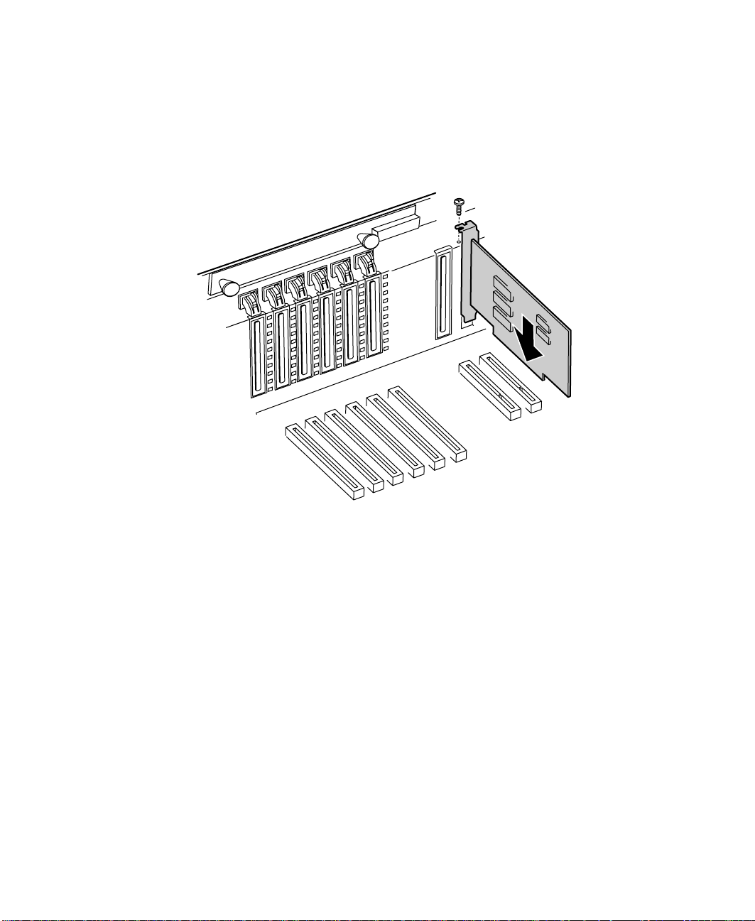
Locate an available slot and remove the slot cover by removing the screw
5
that secures it in place, then pull out the slot cover.
6 Insert the bottom edge of the expansion card (the keyed edge with the
contacts) into the slot on the system board and push in firmly to seat
the card.
7 Replace the screw you removed earlier.
8 Connect any cables to the card (see card documentation for proper cable
orientation).
Expansion cards 81
Page 83

9 Replace the EMI foam in the same orientation it was in when you
removed it.
10 Close the case. (See “Closing the case” on page 31.)
11 Reconnect the peripherals and the power cord, then turn on the server.
Y ou may need to reconfigure the server after installing some expansion cards.
Y ou may also need to install software that came with the card. Check the card
documentation for additional information.
Power supplies
The server ships with as many as three 350-W hot-swap power supply
modules. With all three modules, the server provides N+1 power supply
redundancy, letting you hot-swap a power supply module if one fails. If the
power distribution system fails you must replace the entire power supply.
82 Replacing and Adding Internal Devices
Page 84

Hot-swapping a power supply module
If all three hot-swap power supply modules are installed, you can replace a
failed module without turning the server off.
To replace a hot-swap power supply module:
1 Follow the static electricity precautions in “Preventing static electricity
discharge” on page 25.
2 Determine which power supply has failed by checking the indicator LEDs
or using your server management software.
3 Remove the bezel. (See “Removing the bezel” on page 27.)
4 Loosen the captive thumbscrew at the bottom of the failed power supply
module.
5 Press down on the tab at the top of the failed module and pull the module
out.
6 Pull the power supply module entirely out of the chassis.
Power supplies 83
Page 85

7 Align the rails on the new power supply module with the grooves at the
top and bottom of the power supply and slide the power supply module
in.
8 Slide the module all of the way into the space until the clip at the top
clicks into place, then tighten the thumbscrew at the bottom of the power
supply module.
9 Replace the bezel.
Replacing the powersupply
The redundant 350-W power supply provides all system power. If one of the
components of the power distribution hardware fails, you must replace the
entire power supply.
To replace the power supply:
1 Turn off the server and disconnect the power cord and all peripherals.
2 Remove the bezel and the front top panel. (See “Removing the bezel”
on page 27, “Removing the front top panel” on page 29, and “Preventing
static electricity discharge” on page 25.)
84 Replacing and Adding Internal Devices
Page 86

Remove the four screws that secure the upper drive bay bracket in place,
3
then slide the bracket forward before lifting it from the chassis.
4 Disconnect all cables attached to the power supply. Note their locations
and orientations so you can reconnect them later.
Power supplies 85
Page 87

5 Loosen the captive thumbscrew at the bottom, center of the power supply
front, then slide the power supply forward until it stops.
Captive thumbscrew
6 Tilt the power supply forward and lift it up and back to clear the tab on
the bottom of the chassis.
86 Replacing and Adding Internal Devices
Page 88
Holding the new power supply at an angle, place the new power supply
7
over the tab on the bottom of the chassis, then rotate it so that it rests
flat on the bottom of the chassis.
8 Slide the power supply back to insert the tabs on the back of the power
supply under the slots on the bottom of the chassis.
Captive thumbscrew
Power supplies 87
Page 89

9 Tighten the thumbscrew at the bottom of the power supply to secure it
in place.
10 Place the upper drive bay bracket on the top of the chassis. Make sure
the tabs on the bottom of the bracket fit into the slots at either side of
the chassis.
11 Slide the upper drive bay bracket back to set the tabs, then replace the
four screws you removed in Step 3.
12 Close the case. (See “Closing the case” on page 31.)
13 Reconnect the power cord and all external peripherals, then turn on the
server.
88 Replacing and Adding Internal Devices
Page 90
Fans
The server contains six hot-pluggable fans to keep the internal temperature
down to acceptable levels.
Replacing the fans
The fans are located between the electronics bay and the drive bays. The fans
are hot-plug capable so you do not need shut down the server to replace a fan.
To replace a fan:
1 Remove the back top panel. (See “Removing the back top panel” on
page 28 and “Preventing static electricity discharge” on page 25.)
2 Determine which fan has failed by looking at the fan status LEDs in the
fan tray.
Fans 89
Page 91

3 Place your fingers in the holes on the top of the fan and pull the fan
out of the fan tray. Wait until the fan blades stop rotating before you
put the fan down.
4 Insert the new fan into the fan assembly. Make sure the direction of
rotation and airflow match the direction and airflow of the fan you
removed.
5 Close the case. (See “Closing the case” on page 31.)
Replacing the fan power distribution board
The fan power distribution board rests in the bottom of the fan tray and
distributes power to all of the fans and the fan status LEDs. The fan power
distribution board also provides hardware monitoring for all fans.
To replace the power supply:
1 Turn off the server and disconnect the power cord and all peripherals.
2 Remove both top panels. (See “Opening the case” on page 26 and
“Preventing static electricity discharge” on page 25.)
3 Remove all of the fans from the fan tray.
90 Replacing and Adding Internal Devices
Page 92

Disconnect the cables from the bottom front side of the fan tray. Note
4
the location and orientation of each cable so you can connect them
correctly to the new board.
5 Remove the two screws that secure the hot-plug fan tray, then lift the
tray out of the chassis and place it on a static-free surface.
Fans 91
Page 93

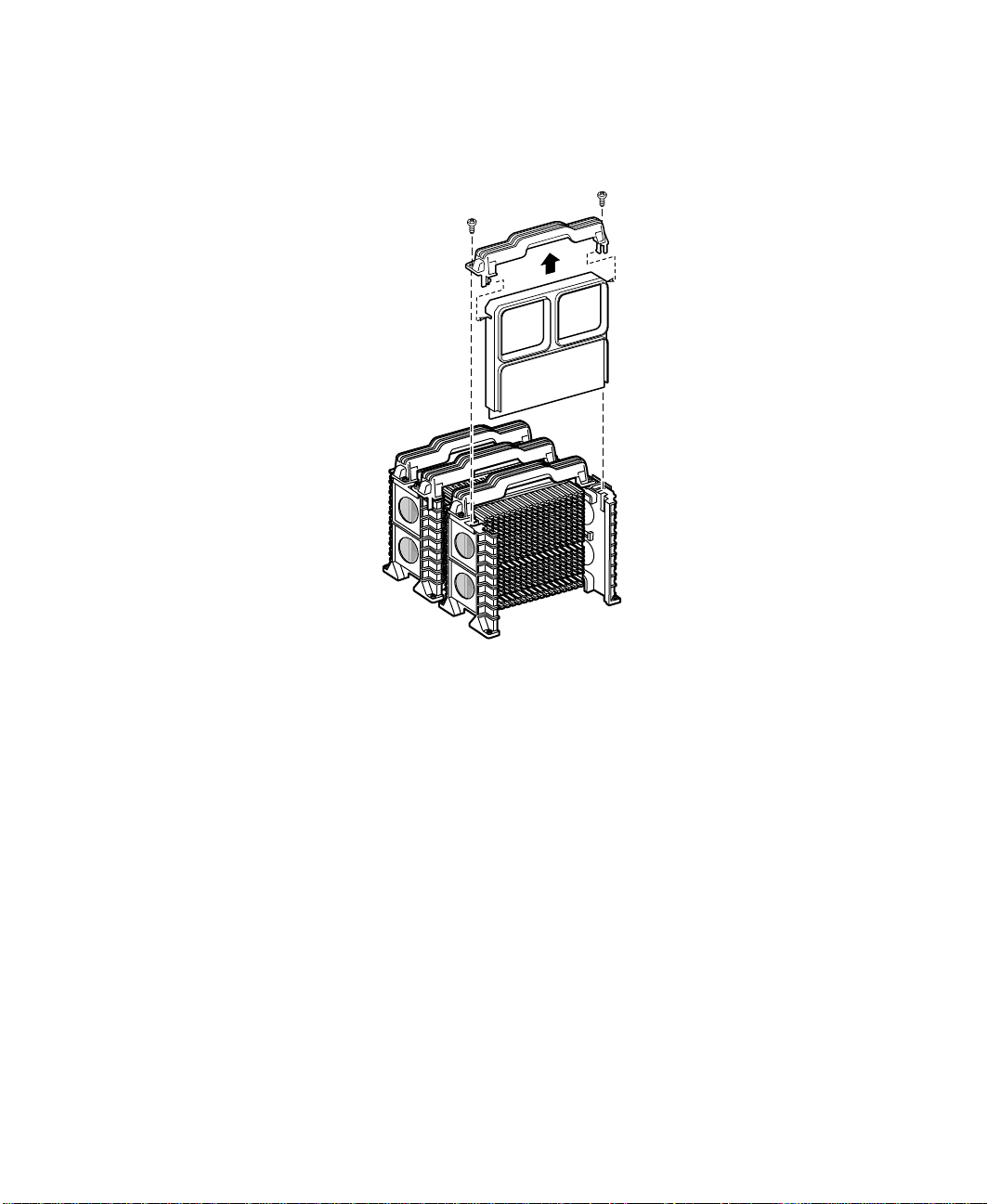
6 Remove the three screws at the bottom of the fan tray, then rotate the
top of the fan tray back on its hinges to expose the fan power distribution
board.
Plastic board
shield
Fan power
distribution board
Top of fan tray
Fan tray
7 Lift off the plastic board shield, then remove the four screws that secure
the fan power distribution board to the bottom of the fan tray and lift
the board out of the tray.
92 Replacing and Adding Internal Devices
Page 94

Place the new fan power distribution board in the fan tray and secure it
8
with the four screws you removed in Step 7.
Plastic board
shield
Fan power
distribution board
Top of fan tray
Fan tray
9 Place the plastic board shield over the fan power distribution board, then
close the fan tray and secure it with the three screws you removed in
Step 6.
Fans 93
Page 95

10 Place the fan tray in the chassis and secure it with the screws you removed
in Step 5.
11 Reconnect the cables you removed in Step 4.
12 Replace all of the fans in the fan tray.
13 Close the case. (See “Closing the case” on page 31.)
14 Reconnect the power cord and all external peripherals, then turn on the
server.
94 Replacing and Adding Internal Devices
Page 96
Replacing the front panel board
The front panel board is mounted on the front of the chassis, inside the front
panel.
To replace the front panel board:
1 Turn off the server and disconnect the power cord and all external
peripherals.
2 Remove the front top panel. (See “Removing the front top panel” on
page 29 and “Preventing static electricity discharge” on page 25.)
3 Remove the two screws that secure the front panel board to the front of
the chassis, then remove the board from the server.
4 Disconnect the cable from the front panel board. Note the location and
orientation of the cable as you remove it.
5 Plug the front panel cable into the connector on the new front panel
board.
Replacing the front panel board 95
Page 97

6 Install the new front panel board by placing the board in position and
replacing the two screws you removed in Step 4.
7 Close the case. (See “Closing the case” on page 31.)
8 Reconnect the power cord and the external peripherals, then turn on the
server.
96 Replacing and Adding Internal Devices
Page 98

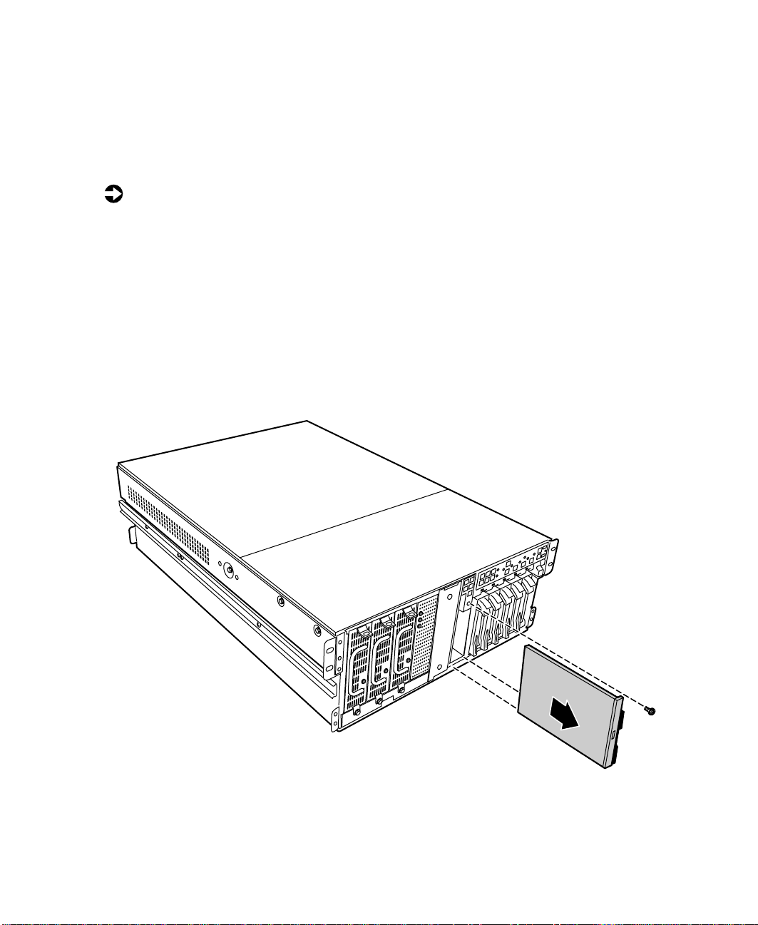
Replacing the hot-plug PCI indicator board
The hot-plug PCI indicator board is mounted on the back panel of the chassis,
above the hot-plug PCI slots.
To replace the hot-plug PCI indicator board:
1 Turn off the server and disconnect the power cord and all external
peripherals.
2 Remove the back top panel. (See “Removing the back top panel” on
page 28 and “Preventing static electricity discharge” on page 25.)
3 Disconnect the cable from the hot-plug PCI indicator board. Note the
location and orientation of the cable as you remove it.
4 Remove the two thumbscrews that secure the board to the back panel,
then remove the board from the server.
Replacing the hot-plug PCI indicator board 97
Page 99

5 Install the new front panel board by placing the board in position and
replacing the two screws you removed in Step 4.
6 Plug the hot-plug PCI indicator board cable into the connector on the
new board.
7 Close the case. (See “Closing the case” on page 31.)
8 Reconnect the power cord and the external peripherals, then turn on the
server.
Replacing the system board
The system board integrates the other elements of the server, such as the
processor, memory, storage, networking, and communications.
To replace the system board:
1 Turn off the server and disconnect the power cord and all external
peripheral devices.
2 Open the case. (See “Opening the case” on page 26 and “Preventing static
electricity discharge” on page 25.)
98 Replacing and Adding Internal Devices
Page 100
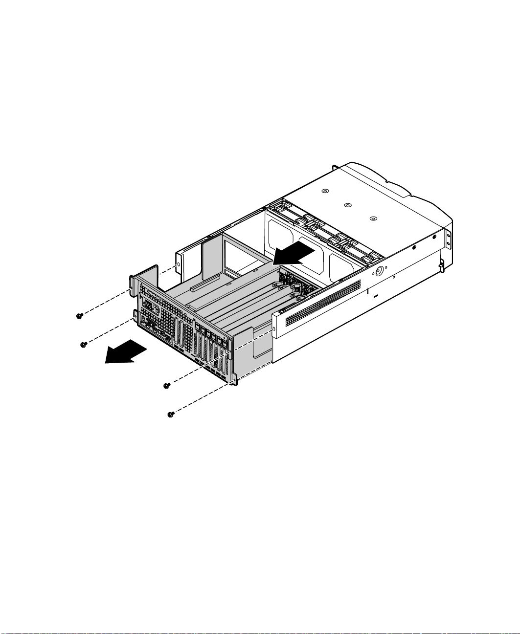
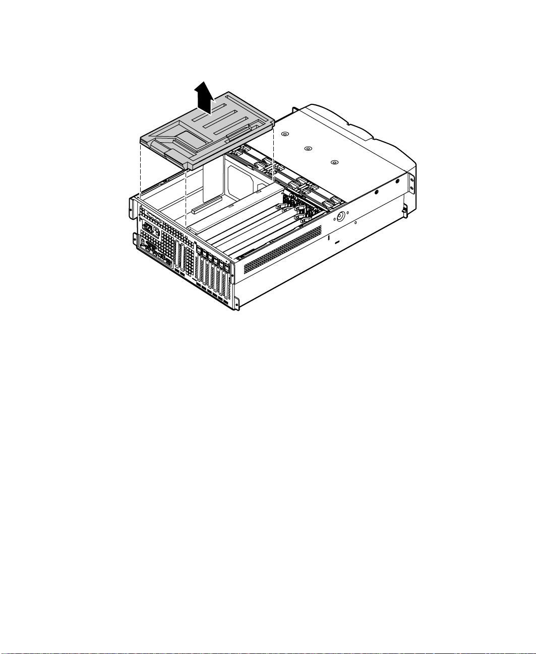
Remove all expansion cards from the server. (See “Replacing a hot-swap
3
PCI card” on page 73 and “Replacing an expansion card” on page 76.)
4 Disconnect all cables from the system board. Note the location and
orientation of each cable as you remove it.
5 Remove the four screws that secure the electronics bay to the chassis, then
pull the electronics bay out through the back panel of the chassis and
place it on a static-free surface.
Replacing the system board 99
 Loading...