

7250R Server
System Manual

Contents
Preface. . . . . . . . . . . . . . . . . . . . . . . . . . . . . . . . . . . . . . . . . . . . . . . . . . . . . . . . . . . . . . v
Conventions used in this manual . . . . . . . . . . . . . . . . . . . . . . . . . . . . . . . . . . . . . . . v
Getting additional information . . . . . . . . . . . . . . . . . . . . . . . . . . . . . . . . . . . . . . . . . . vi
1 System Features . . . . . . . . . . . . . . . . . . . . . . . . . . . . . . . . . . . . . . . . . . . . . . . . 1
Standard features . . . . . . . . . . . . . . . . . . . . . . . . . . . . . . . . . . . . . . . . . . . . . . . . . . . 1
Front panel . . . . . . . . . . . . . . . . . . . . . . . . . . . . . . . . . . . . . . . . . . . . . . . . . . . . . . . . 2
Back panel . . . . . . . . . . . . . . . . . . . . . . . . . . . . . . . . . . . . . . . . . . . . . . . . . . . . . . . . . 3
Interior of system . . . . . . . . . . . . . . . . . . . . . . . . . . . . . . . . . . . . . . . . . . . . . . . . . . . . 4
System board . . . . . . . . . . . . . . . . . . . . . . . . . . . . . . . . . . . . . . . . . . . . . . . . . . . . . . 6
Hot-plug backplane . . . . . . . . . . . . . . . . . . . . . . . . . . . . . . . . . . . . . . . . . . . . . . . . . . 8
Front panel board . . . . . . . . . . . . . . . . . . . . . . . . . . . . . . . . . . . . . . . . . . . . . . . . . . . 9
Riser card . . . . . . . . . . . . . . . . . . . . . . . . . . . . . . . . . . . . . . . . . . . . . . . . . . . . . . . . 10
2 System Setup . . . . . . . . . . . . . . . . . . . . . . . . . . . . . . . . . . . . . . . . . . . . . . . . . . 11
Setting up the server . . . . . . . . . . . . . . . . . . . . . . . . . . . . . . . . . . . . . . . . . . . . . . . . 11
Starting the server . . . . . . . . . . . . . . . . . . . . . . . . . . . . . . . . . . . . . . . . . . . . . . . . . . 12
Understanding the Power-On Self-Test . . . . . . . . . . . . . . . . . . . . . . . . . . . . . . 13
Setting up the operating system . . . . . . . . . . . . . . . . . . . . . . . . . . . . . . . . . . . . 13
Turning off the server . . . . . . . . . . . . . . . . . . . . . . . . . . . . . . . . . . . . . . . . . . . . . . . 13
Resetting the server . . . . . . . . . . . . . . . . . . . . . . . . . . . . . . . . . . . . . . . . . . . . . . . . 15
3 Case Access . . . . . . . . . . . . . . . . . . . . . . . . . . . . . . . . . . . . . . . . . . . . . . . . . . . 17
Preventing static electricity discharge . . . . . . . . . . . . . . . . . . . . . . . . . . . . . . . . . . . 17
Opening the case . . . . . . . . . . . . . . . . . . . . . . . . . . . . . . . . . . . . . . . . . . . . . . . . . . 18
Opening the bezel . . . . . . . . . . . . . . . . . . . . . . . . . . . . . . . . . . . . . . . . . . . . . . . 19
Removing the top panel . . . . . . . . . . . . . . . . . . . . . . . . . . . . . . . . . . . . . . . . . . 19
Closing the case . . . . . . . . . . . . . . . . . . . . . . . . . . . . . . . . . . . . . . . . . . . . . . . . . . . 20
Replacing the top panel . . . . . . . . . . . . . . . . . . . . . . . . . . . . . . . . . . . . . . . . . . 20
Closing the bezel . . . . . . . . . . . . . . . . . . . . . . . . . . . . . . . . . . . . . . . . . . . . . . . 21
4 Replacing and Adding Internal Devices . . . . . . . . . . . . . . . . . . . . . . . . 23
Drives . . . . . . . . . . . . . . . . . . . . . . . . . . . . . . . . . . . . . . . . . . . . . . . . . . . . . . . . . . . . 23
Preparing to replace or add a drive . . . . . . . . . . . . . . . . . . . . . . . . . . . . . . . . . 23
Drive cabling information . . . . . . . . . . . . . . . . . . . . . . . . . . . . . . . . . . . . . . . . . 24
Replacing the diskette drive . . . . . . . . . . . . . . . . . . . . . . . . . . . . . . . . . . . . . . . 24
Replacing a hot-plug drive . . . . . . . . . . . . . . . . . . . . . . . . . . . . . . . . . . . . . . . . 26
Adding a hot-plug drive . . . . . . . . . . . . . . . . . . . . . . . . . . . . . . . . . . . . . . . . . . . 28
i

Replacing the slimline CD drive . . . . . . . . . . . . . . . . . . . . . . . . . . . . . . . . . . . . .30
Memory . . . . . . . . . . . . . . . . . . . . . . . . . . . . . . . . . . . . . . . . . . . . . . . . . . . . . . . . . . .33
Replacing memory . . . . . . . . . . . . . . . . . . . . . . . . . . . . . . . . . . . . . . . . . . . . . . .33
Adding memory . . . . . . . . . . . . . . . . . . . . . . . . . . . . . . . . . . . . . . . . . . . . . . . . .35
Processors . . . . . . . . . . . . . . . . . . . . . . . . . . . . . . . . . . . . . . . . . . . . . . . . . . . . . . . .37
Replacing a processor . . . . . . . . . . . . . . . . . . . . . . . . . . . . . . . . . . . . . . . . . . . .37
Adding a processor . . . . . . . . . . . . . . . . . . . . . . . . . . . . . . . . . . . . . . . . . . . . . .40
Replacing the battery . . . . . . . . . . . . . . . . . . . . . . . . . . . . . . . . . . . . . . . . . . . . . . . .43
Expansion cards . . . . . . . . . . . . . . . . . . . . . . . . . . . . . . . . . . . . . . . . . . . . . . . . . . . .46
Replacing an expansion card . . . . . . . . . . . . . . . . . . . . . . . . . . . . . . . . . . . . . .46
Adding an expansion card . . . . . . . . . . . . . . . . . . . . . . . . . . . . . . . . . . . . . . . . .48
Replacing the power supply . . . . . . . . . . . . . . . . . . . . . . . . . . . . . . . . . . . . . . . . . . .51
Replacing the power distribution board . . . . . . . . . . . . . . . . . . . . . . . . . . . . . . . . . .53
Replacing the fans . . . . . . . . . . . . . . . . . . . . . . . . . . . . . . . . . . . . . . . . . . . . . . . . . .54
Replacing the front panel board . . . . . . . . . . . . . . . . . . . . . . . . . . . . . . . . . . . . . . . .56
Replacing the hot-plug backplane . . . . . . . . . . . . . . . . . . . . . . . . . . . . . . . . . . . . . .57
Replacing the system board . . . . . . . . . . . . . . . . . . . . . . . . . . . . . . . . . . . . . . . . . . .60
5 Using the BIOS Setup Utility . . . . . . . . . . . . . . . . . . . . . . . . . . . . . . . . . . . .65
About the BIOS Setup utility . . . . . . . . . . . . . . . . . . . . . . . . . . . . . . . . . . . . . . . . . . .65
Updating the BIOS . . . . . . . . . . . . . . . . . . . . . . . . . . . . . . . . . . . . . . . . . . . . . . . . . .67
Setting the system board jumpers . . . . . . . . . . . . . . . . . . . . . . . . . . . . . . . . . . . . . .68
The CMOS Clear jumper . . . . . . . . . . . . . . . . . . . . . . . . . . . . . . . . . . . . . . . . . .68
Password Clear jumper . . . . . . . . . . . . . . . . . . . . . . . . . . . . . . . . . . . . . . . . . . .68
Recovery Boot jumper . . . . . . . . . . . . . . . . . . . . . . . . . . . . . . . . . . . . . . . . . . . .69
BIOS Boot Block Write Enable jumper . . . . . . . . . . . . . . . . . . . . . . . . . . . . . . .70
BMC Boot Block Write Enable jumper . . . . . . . . . . . . . . . . . . . . . . . . . . . . . . . .70
FRB Enable jumper . . . . . . . . . . . . . . . . . . . . . . . . . . . . . . . . . . . . . . . . . . . . . .71
Intrusion Detection Enable jumper . . . . . . . . . . . . . . . . . . . . . . . . . . . . . . . . . . .72
BMC Firmware Update jumper . . . . . . . . . . . . . . . . . . . . . . . . . . . . . . . . . . . . .72
WOL Enable jumper . . . . . . . . . . . . . . . . . . . . . . . . . . . . . . . . . . . . . . . . . . . . . .73
6 Managing the Server . . . . . . . . . . . . . . . . . . . . . . . . . . . . . . . . . . . . . . . . . . . .75
Avoiding power source problems . . . . . . . . . . . . . . . . . . . . . . . . . . . . . . . . . . . . . . .75
Surge suppressors . . . . . . . . . . . . . . . . . . . . . . . . . . . . . . . . . . . . . . . . . . . . . . .75
Line conditioners . . . . . . . . . . . . . . . . . . . . . . . . . . . . . . . . . . . . . . . . . . . . . . . .76
Uninterruptible power supplies . . . . . . . . . . . . . . . . . . . . . . . . . . . . . . . . . . . . . .76
Maintain and manage your hard drive . . . . . . . . . . . . . . . . . . . . . . . . . . . . . . . . . . .76
Hard drive maintenance utility . . . . . . . . . . . . . . . . . . . . . . . . . . . . . . . . . . . . . .76
Hard drive management practices . . . . . . . . . . . . . . . . . . . . . . . . . . . . . . . . . . .77
Protecting the server against viruses . . . . . . . . . . . . . . . . . . . . . . . . . . . . . . . . . . . .80
System administration and control . . . . . . . . . . . . . . . . . . . . . . . . . . . . . . . . . . . . . .81
Intel Server Control (ISC) . . . . . . . . . . . . . . . . . . . . . . . . . . . . . . . . . . . . . . . . .81
ii

ManageX Event Manager . . . . . . . . . . . . . . . . . . . . . . . . . . . . . . . . . . . . . . . . . 81
Direct Platform Control (DPC) Console . . . . . . . . . . . . . . . . . . . . . . . . . . . . . . 82
System security . . . . . . . . . . . . . . . . . . . . . . . . . . . . . . . . . . . . . . . . . . . . . . . . . 82
System recovery . . . . . . . . . . . . . . . . . . . . . . . . . . . . . . . . . . . . . . . . . . . . . . . . . . . 86
Creating a startup diskette . . . . . . . . . . . . . . . . . . . . . . . . . . . . . . . . . . . . . . . . 86
Using your Server Companion CD . . . . . . . . . . . . . . . . . . . . . . . . . . . . . . . . . . 86
7 Troubleshooting . . . . . . . . . . . . . . . . . . . . . . . . . . . . . . . . . . . . . . . . . . . . . . . . 87
Introduction . . . . . . . . . . . . . . . . . . . . . . . . . . . . . . . . . . . . . . . . . . . . . . . . . . . . . . . 87
Troubleshooting checklist . . . . . . . . . . . . . . . . . . . . . . . . . . . . . . . . . . . . . . . . . . . . 87
Verifying your configuration . . . . . . . . . . . . . . . . . . . . . . . . . . . . . . . . . . . . . . . 87
Troubleshooting guidelines . . . . . . . . . . . . . . . . . . . . . . . . . . . . . . . . . . . . . . . . 88
CD problems . . . . . . . . . . . . . . . . . . . . . . . . . . . . . . . . . . . . . . . . . . . . . . . . . . . . . . 88
Hard drive problems . . . . . . . . . . . . . . . . . . . . . . . . . . . . . . . . . . . . . . . . . . . . . . . . 89
Memory and processor problems . . . . . . . . . . . . . . . . . . . . . . . . . . . . . . . . . . . . . . 89
Modem problems . . . . . . . . . . . . . . . . . . . . . . . . . . . . . . . . . . . . . . . . . . . . . . . . . . . 90
Peripheral/Adapter problems . . . . . . . . . . . . . . . . . . . . . . . . . . . . . . . . . . . . . . . . . . 91
Printer problems . . . . . . . . . . . . . . . . . . . . . . . . . . . . . . . . . . . . . . . . . . . . . . . . . . . 92
System problems . . . . . . . . . . . . . . . . . . . . . . . . . . . . . . . . . . . . . . . . . . . . . . . . . . . 93
Video problems . . . . . . . . . . . . . . . . . . . . . . . . . . . . . . . . . . . . . . . . . . . . . . . . . . . . 95
Error messages . . . . . . . . . . . . . . . . . . . . . . . . . . . . . . . . . . . . . . . . . . . . . . . . . . . . 97
A Safety, Regulatory, and Notices . . . . . . . . . . . . . . . . . . . . . . . . . . . . . . . 101
B System Specifications . . . . . . . . . . . . . . . . . . . . . . . . . . . . . . . . . . . . . . . . 115
Environmental specifications . . . . . . . . . . . . . . . . . . . . . . . . . . . . . . . . . . . . . . . . . 116
System I/O addresses . . . . . . . . . . . . . . . . . . . . . . . . . . . . . . . . . . . . . . . . . . . . . . 116
Memory map . . . . . . . . . . . . . . . . . . . . . . . . . . . . . . . . . . . . . . . . . . . . . . . . . . . . . 119
Interrupts . . . . . . . . . . . . . . . . . . . . . . . . . . . . . . . . . . . . . . . . . . . . . . . . . . . . . . . . 119
DMA usage . . . . . . . . . . . . . . . . . . . . . . . . . . . . . . . . . . . . . . . . . . . . . . . . . . . . . . 120
Index. . . . . . . . . . . . . . . . . . . . . . . . . . . . . . . . . . . . . . . . . . . . . . . . . . . . . . . . . . . . . . 121
iii

iv
Preface
Conventions used in this manual
Throughout this manual, you will see the following conventions:
Convention Description
ENTER Keyboard key names are printed in small capitals.
C
TRL+ALT+DEL A plus sign means to press the keys at the same time.
Setup Commands to be entered, options to select, and messages that
appear on your monitor are printed in bold.
User’s Guide Names of publications are printed in italic.
Viewpoint All references to front, rear, left, or right on the server are based
on the server being in a normal, upright position, as viewed from
the front.
Important A note labeled important informs you of special
circumstances.
Caution A caution warns you of possible damage to equipment or
loss of data.
Warning A warning indicates the possibility of personal injury.
Conventions used in this manual v

Getting additional information
Log on to the Gateway technical support area at www.gatewayatwork.com to
find information about your system or other Gateway products. Some types
of information you can access are:
■ Hardware driver and program updates
■ Technical tips
■ Service agreement information
■ Technical documents and component information
■ Frequently asked questions (FAQs)
■ Documentation for peripherals or optional components
■ Online technical support
vi Preface

System Features
Standard features
■ As many as two Intel
Bus (FSB) in Slot 1 processor sockets
■ Four Dual Inline Memory Module (DIMM) sockets, that support up to
2.0 GB of PC100 Synchronous Dynamic Random Access Memory
(SDRAM).
■ Intel 440GX chipset
■ Integrated Intel 82559 network controller providing 10/100 LAN support
■ Integrated Super Video Graphics Array (SVGA) video support with 2 MB
of Synchronous Graphics RAM (SGRAM)
■ Two PCI slots on a riser card (additional slots on the system board are
not usable in this chassis)
■ ATX form factor system board
■ One 3.5 inch 1.44 MB diskette drive, one slim-line CD drive, and at least
one hard drive
■ Integrated voltage regulator modules (VRMs) for both processors
®
Pentium III processors with 100 MHz Front Side
1
■ Integrated Adaptec AIC 7896 dual function controller providing both
low-voltage differential (LVD) Ultra2 small computer systems interface
(SCSI) and Ultra Wide single-ended (SE) SCSI support
■ Four drive hot-plug cage
■ Keyboard port (PS/2), mouse port (PS/2), two serial ports, parallel port,
video port, RJ-45 LAN port, and two Universal Serial Bus (USB) ports
Standard features 1
Front panel
Diskette drive Control Panel
Slimline CD drive
Diskette drive writes to and reads from 3.5-inch, 1.44 MB diskettes.
Control panel contains the LED indicators and the power, reset, and sleep
buttons that control the server.
Hot-plug drive bay includes up to four hot-swappable hot-plug drives
connected to a hot-plug backplane. The drive bays support 1.0-inch drives.
Hot plug drives plug into the hot-plug drive bay.
Slimline CD drive plays data or audio CDs
Hot-plug drives
Hot-plug drive bay
2 System Features
Back panel
Mouse port
Keyboard
port
Serial port B
Parallel
port
Serial
port A
Network port
Video port
Expansion
card slots
USB ports Power supp ly fault LED
Power connector
Mouse port connects a PS/2-compatible mouse.
Parallel port connects a printer or other parallel device.
Network port lets you connect to a network. The adjacent indicator LEDs
show LAN activity (yellow) and 100 Mbit speed (green).
Video port connects the first (or only) monitor interface cable. The video
controller is integrated in the system board.
Power connector connects the server power cord. The other end of the power
cord plugs into an AC outlet or power strip.
Power supply fault LED lights when the power supply experiences a fault
condition.
Expansion card slots (2) let you install as many as two 32-bit, 33 MHz PCI
expansion cards.
USB ports connect external Plug-and-Play devices, such as printers and
pointing devices, that are automatically configured when they are plugged
into the server through one of these ports. USB keyboards and mice are not
supported.
Serial ports (2) connect to serial devices.
Keyboard port connects a PS/2-compatible keyboard.
Back panel 3
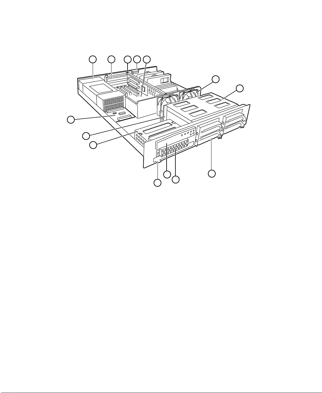
Interior of system
A
N
M
B
C
D
E
F
G
L
J
K
I
H
A Power supply provides power to the system components.
B Expansion slot covers cover the spaces where you can install as
many as two PCI expansion cards.
C Riser card supports as many as two PCI expansion cards.
D Intrusion switch logs a flag when the cover is removed to help
prevent unauthorized access to the chassis.
E System board see “System board” on page 6.
F Fan assembly fans provide cooling for the system.
G Hot-plug bays support up to four 1-inch high 3.25-inch SCA SCSI
hard drives. Empty drive bays contain empty carriers to control
airflow and EMC characteristics.
H Hot-plug drives plug into the hot-plug drive bays.
I Diskette drive bay supports the legacy 3.5-inch diskette drive.
4 System Features

Control panel supports the indicator LEDs and the buttons to
J
control the Server operation.
K Slimline CD drive plays data or audio CDs.
L Secondary drive bay assembly supports the slimline CD drive
and the legacy diskette drive.
M Hot-plug backplane provides the control for the hot-plug drives.
N Power distribution board controls power distribution from the
power supply to the internal components.
Interior of system 5
System board
AC
AA
AK
AG
AE
B
A
AJ
AI
AH
AF
AD
AB
Z
D
C
E
G
F
K
I
J
H
L
M
N
O
P
Q
R
S
A Secondary processor fan connector
B Secondary processor connector
C Primary processor fan connector
D Primary processor connector
E DIMM slots (4)
F Main power connector, 24-pin
G ATX auxiliary power connector, 6-pin
H Fan connector
I Diskette drive connector
6 System Features
Y
X
V
W
T
U

Primary IDE connector
J
K Secondary IDE connector
L ATX front panel connector
M Front panel connector, 16-pin
N Battery
O Isolated server management (ISOL) intelligent management bus
(IMB) connector (not used)
P Jumper J4J2 (BMC boot block write enable)
Q Jumper block (jumper J3J1)
R Jumper block (jumper J2J1)
S Fan connector (hot-plug drive bay fan)
T Server monitor module (SMM) feature connector
U Ultra wide SCSI connector
V Ultra2 SCSI connector
W Hard drive LED connector
X Intelligent chassis management bus (ICMB) connector (not used)
Y Chassis intrusion connector
Z Expansion card connectors (not used)
AA Fan connector (not used)
AB Wake on LAN (WOL) jumper
AC PCI connector used for riser card
AD Expansion card connector (not used)
AE Video connector
AF Dual USB connectors
AG RJ-45 Ethernet LAN connector and LEDs
AH Serial Port A
AI Parallel port
AJ Serial port B
AK Stacked keyboard and mouse ports
System board 7
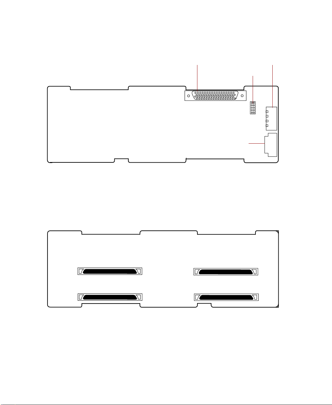
Hot-plug backplane
Back of the hot-plug backplane board
SCSI connector connects the SCSI cable from the RAID controller.
Power connector connects the power cable from the power supply.
Front panel connector carries signals from the backplane to the front panel.
Front of the hot-plug backplane board
Power connectorSCSI connector
Jumper block
Front panel connector
SCA SCSI drive connectors (4) connect the four SCA SCSI drives. Install drives
in increasing order of SCSI ID.
8 System Features
SCSI ID 1SCSI ID 0
SCSI ID 3SCSI ID 2
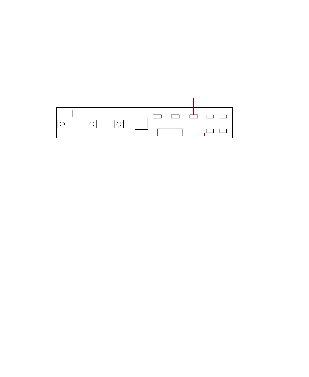
Front panel board
The front panel board supports the LEDs and buttons accessible from the front
panel. The buttons and LEDs on the front panel board are shown and
described below.
Front panel connector
Power LED
Network activity LED
System fault LED
ID0 ID1
ID2 ID3
Power
button
Sleep
button
button
NMI
switch
Backplane
connector
Disk activity/fail LEDsReset
Front panel connector connects the controls on the front panel with the
system board.
Power LED glows green whenever the system is turned on. The LED also
flashes when the system is in sleep mode.
Network activity LED lights whenever there is activity on the network.
System fault LED flashes whenever the system logs a failure.
Disk activity LEDs glow green whenever the hard disk is actively reading or
writing data and glow amber if the disk fails.
Backplane connector carries signals from the hot-plug backplane to the
control panel.
NMI switch allows a technician servicing the server to generate a
non-maskable interrupt (NMI) to help debug server errors.
Reset button lets you reset the server if it has become nonresponsive.
Sleep button lets you put the server into sleep mode to reduce power
consumption.
Power button turns the server on and off.
Front panel board 9
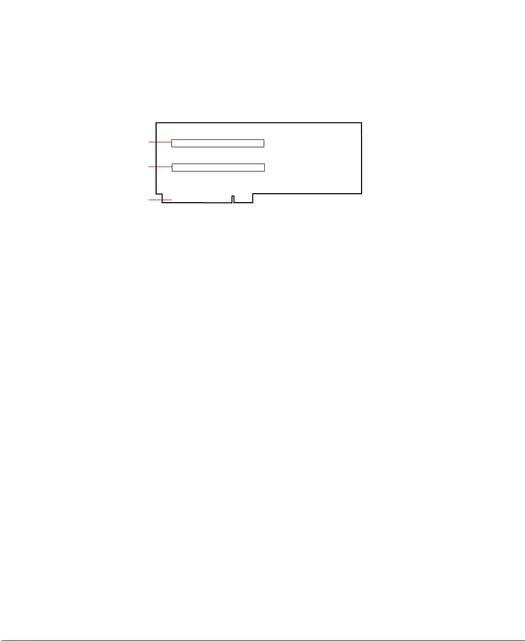
Riser card
The riser card includes a PCI bridge to support the two PCI expansion slots
through the PCI expansion slot on the system board.
PCI Slot 2
PCI Slot 1
Edge connector
PCI expansion slots provide support for as many as two 32-bit, 33MHz PCI
expansion cards. Slot 1 is the lower slot and slot 2 is the upper slot.
Edge connector connects to the PCI slot closest to the processors.
10 System Features

System Setup
Setting up the server
Use the instructions on the quick guide poster that came with the server to
assemble the server.
You can prepare a safer working environment before assembling the server
by following these guidelines:
■ Obtain an adequately rated uninterruptible power supply (UPS). A UPS
protects against AC line spikes, power interruptions, and other power
fluctuations that may damage the server.
■ Protect the server from extreme temperature and humidity. Do not
expose it to direct sunlight, heater ducts, or other heat-generating objects.
■ Keep the server away from equipment that generates magnetic fields,
such as unshielded stereo speakers. Even a telephone placed too close to
the server may cause interference.
■ Plug the server into a wall outlet, power strip, or uninterruptible power
supply (UPS).
2
Important Keep the boxes and packing material. If you need to send
the server to Gateway for repairs, you must use the original
packaging or your wa rranty may be voided .
Setting up the server 11

Starting the server
Before you start the server for the first time, make sure:
■ If the power supply is autosensing, it will not have a voltagte selection
switch and it automatically determines the voltage of the incoming
power source.
■ All cables are firmly connected to the proper ports on the back panel of
the server.
Caution Electricity can flow from connected peripherals into the
system causing a shock. Make sure the server and
peripherals are turned off and unplugged from the power
outlet when you connect peripherals to the server.
■ The server and monitor are plugged into an AC outlet, power strip, or
UPS and that the power strip or UPS is turned on.
To start the system:
1 If you have connected the system components to a power strip or UPS,
make sure all the system components are turned off, then turn on the
power strip or UPS.
2 Turn on the monitor.
3 Turn on the server. The light-emitting diode (LED) on the control panel
is on when the power is on.
4 Turn on any other components connected to the server, such as speakers,
a printer, or a scanner.
If nothing happens when you turn on the system:
■ Make sure that the power cables are securely plugged in and that
the power strip or UPS (if you are using one) is plugged in and
turned on.
■ Make sure the monitor is connected to the server, plugged into the
power strip, AC outlet, or UPS, and turned on. You may also need
to adjust the brightness and contrast controls on the monitor.
12 System Setup

Understanding the Power-On Self-T est
When you turn on your server, the power-on self-test (POST) routine checks
the system memory and components. To see this information on the screen,
press E
The system displays an error message if POST finds any problems. Write down
any error messages that you see. If you continue to have problems, these error
messages may help you or Gateway technical support diagnose the cause.
SC during POST. Press SPACEBAR to bypass the remaining memory count.
Setting up the operatin g system
The first time you start the server, the operating system takes a few minutes
to set up.
Refer to your operating system documentation for specific questions regarding
the operating system.
To complete the operating system setup:
1 After the server starts, the start-up wizard opens. Click Next.
2 Type the requested information in the appropriate text boxes. When you
have finished typing the information, click
3 Continue following the instructions and selecting options in the start-up
wizard dialog boxes, clicking
the wizard tells you to restart your server.
Next to move through the dialog boxes, until
Next.
If you need to return to the previous dialog box to change any of your
entries, click
Back.
4 Restart the server. The setup is complete.
Important For all operating systems, refer to the appropriate
operating system softwa re manual for sp ecific instr uctions.
T urning off the server
Every time you turn off the server, shut down the operating system first. You
may lose data if you do not follow the proper procedure.
Turning off the server 13

To turn off the server in Windows NT:
1 Click Start, then select Shut down the computer?, then Shut Down.
2 Click OK. The operating system shuts down. When you see a message
saying
the power button.
3 Turn off the monitor and peripherals.
Important For other operating systems, such as Windows 2000 or
It is now safe to turn off yo ur computer , turn off the server by pressing
Caution When you turn the server off, some electric current still
flows through it. Before opening the server case or
connecting or removi ng any peripherals, turn of f the server ,
then unplug the power cord.
Novell Netware, refer to th e ap prop ria t e op era ting sy st em
software m anual fo r specific i nstruct ions.
14 System Setup

Resetting the server
If your server does not respond to keyboard or mouse input, you may have
to close programs that are not responding. If closing unresponsive programs
does not restore your server to normal operation, you may have to reset the
system.
To close unresponsive programs and reset the server in Windows NT:
1 Press CTRL+ALT+DEL. A window opens that lets you close a program that
is not responding.
2 Click Tas k Ma n a g er, then select the program that is not responding.
3 Close the program by clicking End Task.
4 If the server does not respond, press the reset button to restart the server.
As a part of the regular startup process, a program to check the disk status
runs automatically. When the checks are finished, Windows starts.
Important For other operating systems, such as Windows 2000 or
Novell Netware, refer to th e ap prop riate operating system
software m anual fo r specific i nstruct ions.
Resetting the server 15

16 System Setup

Case Access
3
Preventing static electricity discharge
Before opening the server case, follow these precautions to prevent damage
from static electricity. When opening your server case, always perform the
following procedure.
Caution Static electricity can permanently damage electronic
components in your server. Prevent electrostatic damage
to your server by following static electricity precautions
every time you open your server case.
To prevent static electricity discharge:
1 Turn off the server power.
2 Touch a bare metal surface on the back of the server.
3 Unplug all power cords from AC outlets and disconnect the modem cable
(if installed).
Also follow these static electricity precautions:
■ Avoid static-causing surfaces such as plastic and packing foam in your
work area.
■ Remove the parts from their antistatic bags or containers only when you
are ready to use them. Do not lay parts on the outside of an antistatic
bag or container because only the inside provides antistatic protection.
■ Always hold cards by the edges and their metal mounting brackets. Avoid
touching components on the cards and the edge connectors that connect
to expansion slots. Never slide cards or other parts over any surface.
Preventing static electricity discharge 17

Opening the case
Important All references to front, back, left, or ri ght on the server are
based on the server being in a normal, upright position,
as viewed from the front.
The only components that are accessible from the outside of the chassis are
the front panel indicator lights. To access any of the removable media drives,
the hot-plug drives, or the front panel buttons you must open the bezel. To
work on the internal components of the server, you must open the chassis.
Because the components inside the server are extremely sensitive to static
electricity, make sure you follow the precautions at the beginning of this
chapter to avoid static electricity damage.
Only qualified personnel should open the system for maintenance. If you are
qualified to maintain the system yourself, make sure you are properly
grounded before opening the system chassis.
Caution Avoid exposure to dangerous electrical voltages and
moving parts by turning off yo ur server and un plugging the
power cord and mod em cable (if inst alled) before removin g
the chassis c over.
18 Case Access
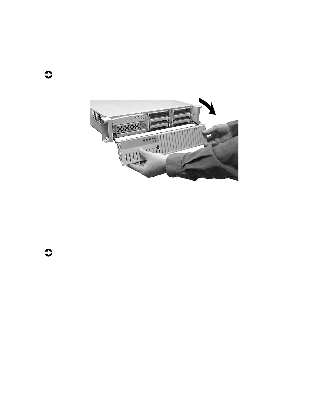
Opening the bezel
The bezel covers the removable media drives, the hot-plug drives, and the
front panel controls. To access these components, you must open the bezel.
To open the bezel:
1 Grip the bezel door and pull the door straight out away from the chassis.
2 Swing the door downward on its hinges so that it rests below the front
of the system.
Removing the top panel
The top panel provides access to all of the internal components of the server.
To remove the top panel:
1 Turn off the server and disconnect all power cords.
2 Observe all safety and static electricity precautions, see “Preventing static
electricity discharge” on page 17.
Opening the case 19
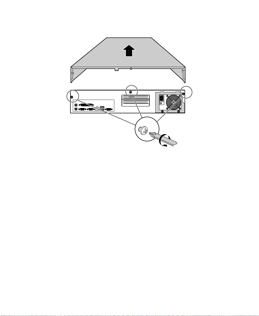
3 Remove the three screws from the top edge of the back panel.
4 Slide the top panel slightly to the back, disengaging the top edge of the
panel from the top of the front panel.
5 Lift the panel out and away from the chassis.
Closing the case
Close the chassis as soon as you finish installing or removing components
so that dust and dirt do not collect inside the server.
Replacing the top panel
You must replace the top panel before you can operate the server. If you do
not, a system intrusion event is logged by the system management hardware.
Be careful not to pinch any cables in the panel as you replace it.
20 Case Access

To replace the top panel:
1 Place the top panel on the top of the chassis approximately 3/4-inch back
from the front of the server.
2 Slide the panel toward the front of the chassis 3/4-inch, securing it in
place. The tabs on the front of the top panel slide under the lip of the
front panel.
3 Replace the screws you removed earlier.
Closing the bezel
Close the bezel to prevent accidental or unauthorized access to the server
controls, hot-plug drives, and removable media drives. To close the bezel,
swing the bezel up and press it firmly into place.
Closing the case 21

22 Case Access

Replacing and Adding Internal Devices
Drives
There are several types of drives and similar devices that can be installed in
the server.
Preparing to replace or add a drive
One 3.5-inch diskette drive, at least one 1-inch high 3.5-inch hot-plug hard
drive, and one slimline CD drive are included with the server. You can add
up to three additional 3.5-inch hot-plug drives for a total of four hot-plug
drives.
As you prepare to install drives, keep the following in mind:
■ If you remove a drive, place it in an antistatic bag or container.
■ Before you install a drive, see the drive documentation for information
on configuring the drive, setting any jumpers on the drive, and attaching
cables to the drive.
4
■ If you are installing a drive that uses an add-in controller, install the
expansion card before you install the drive.
■ You may need to configure the drives you install using the BIOS Setup
utility or the SCSISelect utility. Press F2 at start up to open the BIOS Setup
utility or press C
TRL+A to enter the SCSISelect utility.
Drives 23

Drive cabling information
The system includes three different types of drive cables. Each drive cable is
clearly labeled, indicating the cable type and showing which end to connect
to the appropriate connector on the system board and which end to connect
to the drive.
■ Use the diskette drive connector cable to connect the diskette drive.
■ Use the standard IDE connector cable to connect the CD drive.
■ Use the SCSI LVD cable to connect the hot-plug backplane to the
integrated SCSI controller on the system board.
Replacing the diskette drive
The diskette drive is immediately below the control panel.
To replace the diskette drive:
1 Turn off the system and disconnect the power cord and all other external
peripheral devices.
2 Open the case. (See “Opening the case” on page 18 and “Preventing static
electricity discharge” on page 17.)
3 Remove the power and data cables from the back of the drive, noting
their locations and orientations. (You will reconnect these cables after you
install the new drive.)
24 Replacing and Adding Internal Devices

Remove the diskette drive tray by removing the two screws from the front
4
panel.
5 Pull the tray out of the chassis.
6 Remove the drive from the tray by removing the four screws that secure
the drive to the tray.
Drives 25

7 If necessary, set any jumpers on the drive. (See your drive documentation
for proper drive jumper settings and cable orientation.)
8 Attach the tray to the new drive by reinstalling the screws you removed
in Step 6.
9 Replace the tray in the chassis using the screws you removed in Step 4
to secure the tray in position.
10 Connect the power and data cables, making sure the cables are in their
original positions.
11 Close the case. (See “Closing the case” on page 20.)
12 Reconnect the power cord and all other external peripheral devices, then
turn on the system.
Replacing a hot-plug drive
The hot-plug drives are located at right side of the front panel as you face
the system. The hot-plug bay supports as many as four 1-inch high 3.5-inch
SCSI hard drives.
The hot-plug drives are assigned SCSI ID numbers by the hot-plug backplane
with the drive in the upper left corner of the hot-plug bay assigned SCSI ID 0.
The backplane assigns SCSI IDs to the other drives in order up to SCSI ID 3
in the lower right corner of the hot-plug bay. See “Hot-plug backplane” on
page 8 for the locations of the drives by SCSI ID number.
Important Gateway tests and verifie s the operatio n and compati bility
of the drives we sell. Addit ional or replacement drive s must
conform to Gateway standards, especially in a RAID or
mission-critical environment.
Install the first drive in the upper left corner, then install drives in increasing
order by SCSI ID number thereafter.
26 Replacing and Adding Internal Devices

To replace a failed drive:
1 Before you remove the failed drive, use the appropriate software and
utilities installed on the system to stop all activity on the failed drive.
Instructions for using the software are provided by the software
manufacturer.
2 Use the utilities or look at the drive indicator LEDs on the front panel
to determine which drive needs to be replaced.
3 Remove the drive from the drive bay by unclipping the retention lever
and rotating the lever out away from the front of the system.
4 Continue pulling outward until the drive is entirely out of the system,
holding the top edge of the carrier to make sure the drive exits the chassis
smoothly.
5 Remove the four screws that secure the drive to the carrier, then remove
the drive.
Drives 27

6 Install the new drive in the carrier using the four screws you removed
in Step 5.
7 Align the drive rails with the slots at the sides of the drive bay. Leave
the retention lever in the open position.
8 Push the drive all of the way into the drive bay until the retention lever
starts to close because of contact with the front of the chassis. Make sure
the hooks on the side of the retention lever latch to the side of the drive
bay and firmly close the lever.
9 Run any necessary utilities to setup the new drive. See the utility software
documentation for details.
Adding a hot-plug drive
The hot-plug drives are located at right side of the front panel as you face
the system. The hot-plug bay supports as many as four 1-inch high 3.5-inch
SCSI hard drives.
The hot-plug drives are assigned SCSI ID numbers by the hot-plug backplane
with the drive in the upper left corner of the hot-plug bay assigned SCSI ID 0.
The backplane assigns SCSI IDs to the other drives in order up to SCSI ID 3
in the lower right corner of the hot-plug bay. See “Hot-plug backplane” on
page 8 for the locations of the drives by SCSI ID number.
Important Gateway tests and verifie s the operatio n and compati bility
of the drives we sell. Addit ional or replacement drive s must
conform to Gateway standards, especially in a RAID or
mission-critical environment.
Install the first drive in the upper left corner, then install drives in increasing
order by SCSI ID number thereafter.
28 Replacing and Adding Internal Devices

To install an additional hot-plug drive:
1 Remove the drive carrier from the drive bay by unclipping the retention
lever and rotating the lever out away from the front of the system.
2 Continue pulling outward until the drive carrier is entirely out of the
system.
3 Remove the four screws that secure the air baffles to the carrier, then
remove the air baffles.
Drives 29

4 Install the new drive in the carrier using the four screws you removed
in Step 3.
5 Align the drive rails with the slots at the sides of the drive bay. Leave
the retention lever in the open position.
6 Push the drive all of the way into the drive bay until the retention lever
starts to close because of contact with the front of the chassis. Make sure
the hooks on the side of the retention lever latch on the side of the drive
bay and firmly close the lever.
7 Run any necessary utilities to setup the new drive. See the utility software
documentation for details.
Replacing the slimline CD drive
The slimline CD drive is located below the diskette drive on the left side of
the front panel.
To replace the slimline CD drive:
1 Turn off the system and disconnect the power cord and all other external
peripheral devices.
2 Open the case. (See “Opening the case” on page 18 and “Preventing static
electricity discharge” on page 17.)
30 Replacing and Adding Internal Devices

For easier access to the CD drive, remove the cables to the diskette drive
3
as described in “Replacing the diskette drive” on page 24. Note the
orientation of the cables so you can replace them later.
4 Remove the power and data cables from the back of the CD drive, noting
their locations and orientations. (You will reconnect these cables after you
install the new drive.)
5 Loosen the three captive thumbscrews that secure the CD drive tray to
the chassis.
6 Slide the CD drive tray out of the front of the chassis.
7 Remove the CD drive from the tray by removing the three screws that
secure the drive to the tray and disconnecting the drive connector at the
back of the tray.
8 Place the new drive on the tray, connecting the drive to the tray
connector and replacing the three screws you removed in Step 7.
Drives 31

9 Reinstall the CD drive tray in the chassis and secure it with the three
screws you removed in Step 5.
10 Connect the power and data cables, making sure the cables are in their
original positions. (See your drive documentation for proper cable
orientation.)
11 Reconnect the diskette drive cables using the instructions in “Replacing
the diskette drive” on page 24.
12 Close the case. (See “Closing the case” on page 20.)
13 Reconnect the power cord and all other external peripheral devices, then
turn on the system.
32 Replacing and Adding Internal Devices

Memory
Four DIMM sockets on the system board support up to 2.0 Gigabytes (GB) of
PC/100 SDRAM.
Replacing memory
The DRAM DIMMs supported by the system board conform to the following
standards:
■ 128 MB, 256 MB, and 512 MB ECC DIMMs
■ PC/100-compliant, unbuffered, ECC SDRAM
■ 128 MB minimum system memory
■ 2.0 GB maximum system memory
When you select and install DIMMs, keep the following in mind:
■ Registered DIMMs should not be combined with unbuffered DIMMs
■ Memory should be added in order, from DIMM 1 to DIMM 4.
■ There can be no empty slots between installed DIMMs.
■ No jumper settings are required for the memory size or type because the
BIOS automatically detects this information.
To replace DIMMs:
1 Turn off the system and disconnect the power cord and all other external
peripheral devices.
2 Open the case. (See “Opening the case” on page 18 and “Preventing static
electricity discharge” on page 17.)
Memory 33

3 Pull open the socket clamps on each side of the DIMM socket, then lift
the DIMM out of the socket. Store the DIMM in an anti-static container.
4 Insert the new DIMM into the socket, aligning the two notches in the
DIMM with the two notches in the DIMM socket.
5 Gently press the DIMM into the socket until it is firmly seated. Inserting
the DIMM automatically locks the socket clamps on each end of the
DIMM.
6 Close the case. (See “Closing the case” on page 20.)
7 Reconnect the peripherals and the power cord, then turn on the system.
34 Replacing and Adding Internal Devices

Adding memory
The DRAM DIMMs supported by the server board conform to the following
standards:
■ 128 MB, 256 MB, and 512 MB ECC DIMMs
■ PC/100-compliant, unbuffered, ECC SDRAM
■ 128 MB minimum system memory
■ 2.0 GB maximum system memory
When you select and install DIMMs, keep the following in mind:
■ Registered DIMMs should not be combined with unbuffered DIMMs
■ Memory should be added in order, from DIMM 1 to DIMM 4.
■ There can be no empty slots between installed DIMMs.
■ No jumper settings are required for the memory size or type because the
BIOS automatically detects this information.
To add DIMMs:
1 Turn off the system and disconnect the power cord and all other external
peripheral devices.
2 Open the case. (See “Opening the case” on page 18 and “Preventing static
electricity discharge” on page 17.)
3 Pull open the socket clamps on each side of the DIMM socket.
4 Insert the new DIMM into the socket, aligning the two notches in the
DIMM with the two notches in the DIMM socket.
Memory 35

5 Gently press the DIMM into the socket until it is firmly seated. Inserting
the DIMM automatically locks the socket clamps on each end of the
DIMM.
6 Close the case. (See “Closing the case” on page 20.)
7 Reconnect the peripherals and the power cord, then turn on the system.
36 Replacing and Adding Internal Devices

Processors
The system is compatible with the Intel® Pentium® III 600 MHz and faster
processors with 100 MHz front-side bus (FSB). As many as two processors may
be installed in the system. You do not need to install additional voltage
regulator modules (VRMs), because the VRMs for both processors are built into
the system board.
Replacing a processor
When replacing a processor, order a processor upgrade kit from Gateway. The
kit includes the processor, a fansink or heatsink, and a disposable grounding
wrist strap.
Caution A heatsink or fa nsink must be inst alled o n each process or.
Installing a processor without a heatsink or fansink could
result in damage to, or failure of, the processor.
To replace a processor:
1 Turn off the system and disconnect the power cord and all external
peripheral devices.
2 Open the case by following the instructions on page 18. (See “Preventing
static electricity discharge” on page 17.)
3 Disconnect the processor fan cable from the processor fan connector on
the system board.
Processors 37

4 Place the head of a flat-bladed screwdriver between the processor module
and the tab on the side of one of the processor retention brackets that
hold the processor to be removed.
5 Push the handle of the screwdriver toward the processor. When the tab
that locks the processor in place opens, lift up slightly on the side of the
processor.
6 Repeat the previous two steps for the other side of the processor.
38 Replacing and Adding Internal Devices

Pull the processor up and out of the slot.
7
8 If the heatseink is separate, attach it to the processor.
Processors 39

9 Align the new processor with the processor slot (note that the processor
slot is keyed so the processor can only be installed one way) and press
firmly to install it.
10 Reconnect the processor fan cable to the processor fan connector on the
system board.
11 Close the case. (See “Closing the case” on page 20.)
12 Reconnect the power cord and all other cords you removed, then turn
on the system.
Important Gateway recommends that you run a processor retest from
the BIOS Setup utility whenever you replace or add a
processor.
Adding a processor
The system is compatible with the Intel® Pentium® III 600 MHz and faster
processors with 100 MHz front-side bus (FSB). As many as two processors may
be installed in the system. The second processor must match the first processor
in speed or the system functions at the speed of the slowest processor.
40 Replacing and Adding Internal Devices

When adding a second processor order a processor upgrade kit from Gateway.
The kit includes the processor, a fansink or heatsink, and a disposable
grounding wrist strap.
Caution A heatsink or fa nsink must be inst alled o n each process or.
Installing a processor without a heatsink or fansink could
result in damage to, or failure of, the processor.
To add a second processor:
1 Turn off the system and disconnect the power cord and all external
peripheral devices.
2 Open the case. (See “Opening the case” on page 18 and “Preventing static
electricity discharge” on page 17.)
3 Remove the terminator card from the second processor slot to make room
for the additional processor.
4 If the heatseink is separate, attach it to the processor.
Processors 41

5 Align the new processor with the processor slot. Note that the processor
slot is keyed so the processor can only be installed one way. Press it firmly
to install it.
6 Connect the processor fan cable to the secondary processor fan connector
on the system board (See “System board” on page 6 for location).
7 Close the case. (See “Closing the case” on page 20.)
8 Reconnect the power cord and all other cords you removed, then turn
on the system.
Important Gateway recommends that you run a processor retest from
the BIOS Setup utility whenever you replace or add a
processor.
42 Replacing and Adding Internal Devices

Replacing the battery
The battery provides power for the system real-time clock and CMOS memory,
which holds the system configuration information.
If your battery is failing you may notice the server clock slowing down and
giving you the incorrect time.
Open the BIOS Setup utility and write down all the values in the various
menus before replacing the battery. Replacing the battery resets the BIOS Setup
utility to its default values.
Warning Danger of explosion if battery is incorrectly replaced.
Replace only with the same or equivalent type
recommended by manufacturer.
Dispose of used batteries according to manufacturer’s
instructions.
Warnung Explosionsgefahr bel falsch eingebautter batterie.
Ersetzen der batterien nur mit batterien des gleichen typs
oder mit batterien vom hersteller empfohlenen typs.
Entsorgen gebrauchter batterien entsprechned
herstellerangaben.
Attention Il y a danger d’explosion s’il y a replacement incorrect de
la batteri e.
Remplacer uniquement avec une batterie du même type
ou d’un type équivalent recommandé par le constructeur.
Mettre au rebut les batteries usagées conformément aux
instructions du fabricant.
To replace the battery:
1 Restart the server and start the BIOS Setup utility.
2 Write down the CMOS values from each tab in the BIOS Setup utility so
you can reenter them after you replace the battery. For more information
about the BIOS Setup utility, see “About the BIOS Setup utility” on
page 65.
Replacing the battery 43

3 Turn off the server, disconnect the power cord and all external peripheral
devices.
4 Open the case by following the instructions on page 18. (See “Preventing
static electricity discharge” on page 17.)
5 Locate the battery on the system board (see “System board” on page 6).
The battery is circular and has the positive pole mark (+) on the top.
6 Using a small, flat-bladed screwdriver, carefully remove the battery from
its socket on the system board.
7 Press the new battery in the socket with the positive pole up. Be sure you
have pressed the battery down far enough for it to contact the base of
the socket (it should snap into place).
8 Close the case, as described in “Closing the case” on page 20.
9 Reconnect the peripherals and the power cord, then turn on the system.
10 If the CMOS data is not correct, change the information in the BIOS Setup
utility using the data you recorded in Step 2.
Tr oubleshooting the battery installati on
If you have problems after installing the new battery, try each of the items
listed below, restarting the server after each try.
■ Turn off the server and make sure that all exterior cables are attached
and secured to the correct connectors.
■ Make sure that all power switches are on. If the server is plugged into a
power strip or surge protector, make sure it is turned on also.
■ Enter the BIOS Setup utility and compare the settings on the screen with
your notes or the system hardware manuals. Correct any discrepancies.
44 Replacing and Adding Internal Devices

■ Turn off the server, remove the cover, and make sure that all cables inside
the case are attached securely. Also, make sure that the colored cable edges
are aligned correctly and that the connectors did not miss any pins.
Disconnect and reconnect the cables. Close the case as described in
“Closing the case” on page 20, reconnect the modem and power cords,
then turn on the server.
■ Turn off the server, remove the cover and, if you have the proper test
equipment, make sure that the new battery has power. (Although
unlikely, your new battery may be defective.) Close the case as described
in “Closing the case” on page 20, reconnect the power cord, then turn
on the server.
Replacing the battery 45

Expansion cards
The server has two expansion slots on the riser card that can be used for a
variety of expansion cards. These slots support 32-bit, 33 MHz PCI cards. Both
slots will hold full-length cards. The expansion slots on the system board are
not used.
Replacing an expansion card
You must install an expansion card in slot 1 before you can install an
expansion card in slot 2.
To replace an expansion card:
1 Set any jumpers and switches on the replacement card, if required in the
card instructions.
2 Turn off the server, then disconnect the power cord and all external
peripheral devices.
3 Open the case. (See “Opening the case” on page 18 and “Preventing static
electricity discharge” on page 17.)
4 Disconnect any cables attached to the card.
5 Loosen the captive thumbscrew that holds the expansion slot cover
bracket in place and remove the expansion slot cover bracket.
46 Replacing and Adding Internal Devices

If the card is a full length card, slide the card guide behind the fans by
6
pushing out the lever and sliding the card guide to the side until it locks
into place, then remove the expansion card from the system.
7 If the replacement riser card has an ISA retainer (a plastic piece on the
end of the card), remove the ISA retainer, then install the expansion card
in the chassis. PCI slot 1 is the bottom slot and PCI slot 2 is the top slot.
Expansion cards 47

8 Replace the expansion slot cover bracket and tighten the thumbscrew.
9 Replace the card guide by sliding it back to its original position until it
clicks in place. Make sure the end of the card is in the right slot in the
card guide.
10 Connect any cables to the card (see card documentation for proper cable
orientation).
11 Close the case. (See “Closing the case” on page 20.)
12 Reconnect the peripherals and the power cord, then turn on the system.
You may need to reconfigure the server after replacing an expansion card. You
may also need to install upgrade software that came with the card. Check the
card documentation for additional information.
Adding an expansion card
When adding an expansion card, you must install an expansion card in slot 1
before you can install an expansion card in slot 2.
To add an expansion card:
1 Set any jumpers and switches on the card, if required in the card
instructions.
2 Turn off the server, disconnect the power cord and all external peripheral
devices.
3 Open the case. (See “Opening the case” on page 18 and “Preventing static
electricity discharge” on page 17.)
48 Replacing and Adding Internal Devices

Locate an available slot and remove the slot cover by removing the
4
thumbscrew on the slot cover bracket, then remove the slot cover bracket.
PCI slot 1 is the bottom slot and PCI slot 2 is the top slot.
5 Pull out the slot cover.
Expansion cards 49

6 If the card is a full-length expansion card, press the lever to release the
card guide and slide the card guide to the side.
7 Insert the bottom edge of the expansion card (the keyed edge with the
contacts) into the slot on the riser card and push in firmly to seat the card.
50 Replacing and Adding Internal Devices

Replace the expansion slot cover bracket and tighten the thumbscrew.
8
9 Replace the card guide by sliding it back to its original position until it
clicks in place. Make sure the end of the card is in the right slot in the
card guide.
10 Connect any cables to the card (see card documentation for proper cable
orientation).
11 Close the case. (See “Closing the case” on page 20.)
12 Reconnect the peripherals and the power cord, then turn on the system.
You may need to reconfigure the server after installing some expansion cards.
You may also need to install software that came with the card. Check the card
documentation for additional information.
Replacing the power supply
The 275-W power supply provides all system power through a power
distribution board.
To replace the power supply:
1 Turn off the system and disconnect the power cord and all peripherals.
2 Open the case. (See “Opening the case” on page 18 and “Preventing static
electricity discharge” on page 17.)
Replacing the power supply 51

3 Open the power supply cover by removing the two screws that secure it
in place, then swing the cover up.
4 Holding the sides of the power supply, push it out through the back panel
of the chassis.
5 Insert the new power supply through the back panel, making sure that
the connectors on the power supply seat firmly in the connectors on the
power distribution board.
6 Close the power supply cover and replace the screws you removed in
Step 3.
7 Close the case. (See “Closing the case” on page 20.)
8 Reconnect the power cord and all external peripherals, then turn on the
system.
52 Replacing and Adding Internal Devices

Replacing the power distribution board
The power distribution board is beside the power supply and serves to separate
the power produced by the power supply into the voltages needed by the
various internal components.
To replace the power distribution board:
1 Turn off the system and disconnect the power cord and external
peripherals.
2 Open the case. (See “Opening the case” on page 18 and “Preventing static
electricity discharge” on page 17.)
3 Remove the power supply as described in “Replacing the power supply”
on page 51.
4 Unplug the cables that connect the power distribution board to other
system components. Note the location and orientation of each cable
before you remove it.
5 Remove the four screws that secure the board to the chassis, then remove
the power distribution board.
Screws
Replacing the power distribution board 53

6 Place the replacement board in the chassis in the same orientation as the
original board, then replace the four screws you removed in Step 5.
7 Reconnect the cables to the board at the same locations and in the same
orientations as they were originally connected.
8 Replace the power supply.
9 Close the case. (See “Closing the case” on page 20.)
10 Reconnect the power cord and external peripherals, then turn on the
system.
Replacing the fans
The fans are located between the system board and the hot plug drive cage.
The fans are not hot-plug capable and you must shut down the system to
replace a fan.
To replace a fan:
1 Turn off the system and disconnect the power cord and external
peripherals.
2 Open the case. (See “Opening the case” on page 18 and “Preventing static
electricity discharge” on page 17.)
3 Unplug the fan cables from the system board.
54 Replacing and Adding Internal Devices

Pull out on the tabs on both sides of the fan and lift the fan out of the
4
fan assembly.
Tabs
5 Insert the new fan into the fan assembly. Make sure the direction of
rotation and airflow match the direction and airflow of the fan you
removed.
6 Plug the fan connector into the connector on the system board. Fan 1
plugs into connector J1J1 and fan 2 plugs into connector J1G6.
7 Close the case. (See “Closing the case” on page 20.)
8 Reconnect the power cord and external peripherals, then turn on the
system.
Replacing the fans 55

Replacing the front panel board
The front panel board is mounted on the front of the chassis, inside the front
panel.
To replace the front panel board:
1 Turn off the system and disconnect the power cord and all external
peripherals.
2 Open the case. (See “Opening the case” on page 18 and “Preventing static
electricity discharge” on page 17.)
3 Disconnect all cables from the front panel board. Note the location and
orientation of each cable as you remove it.
4 Remove the two screws that secure the board to the front of the chassis,
then remove the board from the system.
Screw
Screw
5 Install the new front panel board by replacing the two screws you
removed in Step 4.
6 Plug the front panel cables into the appropriate connectors on the front
panel board.
7 Close the case. (See “Closing the case” on page 20.)
8 Reconnect the power cord and the external peripherals, then turn on the
system.
56 Replacing and Adding Internal Devices

Replacing the hot-plug backplane
The four drive hot-plug backplane is at the back of the hot-plug drive cage.
The backplane supports as many as four hot-swappable LVD SCSI drives.
To replace the hot-plug backplane:
1 Turn off the system and disconnect the power cord and all external
peripheral devices.
2 Open the case. (See “Opening the case” on page 18 and “Preventing static
electricity discharge” on page 17.)
3 Disconnect all cables to the hot-plug backplane, noting the connectors
so you can reconnect them after replacing the backplane.
4 Remove all hot-plug drives, being careful to note which drive was in
which slot.
5 Remove the six screws that secure the hot-plug drive bay in the chassis.
6 Tilt the bay forward to clear the tabs at the bottom from the slots in the
chassis, then lift the drive bay out of the system.
Replacing the hot-plug backplane 57

7 Remove the six screws that secure the backplane to the hot-plug drive
bay and remove the backplane.
Screw
Screw
Screw
Screw Screw
Screw
8 Set any jumpers on the new backplane for your configuration.
9 Secure the new backplane to the back of the hot-plug drive bay with the
six screws you removed in Step 7.
58 Replacing and Adding Internal Devices

Replace the drive bay in the chassis. Make sure the tabs on the bottom
10
of the drive bay fit into the slots on the bottom of the chassis and the
drive bay sits flat on the bottom of the chassis.
11 Replace the six screws you removed in Step 5.
12 Reconnect all cables on the backplane to the correct connectors.
13 Replace all hot-plug drives. Make sure that you replace them in the same
slots that they were in before you removed them.
14 Close the case. (See “Closing the case” on page 20.)
15 Reconnect all peripherals and the power cord, then turn on the system.
Replacing the hot-plug backplane 59

Replacing the system board
The system board integrates the other elements of the system, such as the
processor, memory, storage, networking, and communications.
To replace the system board:
1 Turn off the system and disconnect the power cord and all external
peripheral devices.
2 Open the case. (See “Opening the case” on page 18 and “Preventing static
electricity discharge” on page 17.)
3 Remove all expansion cards from the system. (See “Replacing an
expansion card” on page 46.)
4 Remove the two screws that secure the riser card assembly to the chassis,
then lift the riser card assembly out of the chassis.
5 Disconnect all cables from the system board. Note the location and
orientation of each cable before you remove it so you can replace it when
you have installed the new system board.
60 Replacing and Adding Internal Devices

Remove the three screws that secure the fan assembly to the chassis, then
6
lift the fan assembly up and place it on the hot-plug drive bay.
Screw
Screw
Screw
7 Remove any processors and DIMMs that you will install in the new
system board. (See “Replacing memory” on page 33 and “Replacing a
processor” on page 37.)
Replacing the system board 61

8 Remove the eleven screws that secure the system board to the chassis,
then lift the system board out of the chassis.
9 Remove the new system board from its anti-static bag and set any jumpers
that you may need to set for your configuration. See “System board” on
page 6 and “Setting the system board jumpers” on page 68.
62 Replacing and Adding Internal Devices

Place the new system board in the chassis. Make sure the two standoffs
10
with shoulders fit into the matching holes in the system board.
11 Replace the eleven screws you removed in Step 8.
12 Install the DIMM(s) and processor(s) in the new system board. (See
“Replacing memory” on page 33 and “Replacing a processor” on
page 37.)
13 Replace the fan assembly using the three screws you removed in Step 6.
14 Reconnect the system cables to the appropriate connectors on the system
board. See “System board” on page 6 for reference.
15 Replace the riser card using the two screws you removed in Step 4. Make
sure you seat the riser card securely into the proper connector on the
system board.
Replacing the system board 63

16 Replace any expansion cards you removed from the system in Step 3. (See
“Replacing an expansion card” on page 46.)
17 Close the case. (See “Closing the case” on page 20.)
18 Reconnect all peripherals and the power cord, then turn on the system.
64 Replacing and Adding Internal Devices

Using the BIOS Setup Utility
About the BIOS Setup utility
The server BIOS has a built-in setup utility that lets you configure several basic
system characteristics. The settings are stored in battery-backed RAM and are
retained even when the power is off.
Enter the BIOS Setup utility by restarting the server, then pressing F2 when
prompted during the startup process. The Main BIOS Setup utility screen
opens. It may not look exactly like the screen shown below.
BIOS Setup Utility
Main Advanced Security Server Boot Exit
Item Specific Help
System Time:
System Date:
Legacy Diskette A:
Legacy Diskette B:
Hard Disk Pre-Delay:
Primary IDE Master:
Primary IDE Slave:
Secondary IDE Master:
Secondary IDE Slave:
Processor Settings:
[xx:xx:xx]
[xx/xx/xxxx]
[ ]
[ ]
[enabled]
[auto]
[ ]
[ ]
[ ]
5
Language:
F1 Help
ESC Exit ←→ Select Menu ENTER Select > Sub-Menu F10 Save & Exit
↑↓ Select Item -/+ Change Values F9 Setup Defaults
[English (US)]
About the BIOS Setup utility 65

As you select items on the Main menu or in submenus, you see specific
information related to the current selection in the Item Specific Help box.
The command bar shows the keystrokes necessary to access help, navigate
through the menus, and perform other functions.
■ F1 opens the Help screen, providing general help for using the BIOS Setup
utility.
■ The ↑ (up arrow) and ↓ (down arrow) keys select items in the menu.
■ The ← (left arrow) and → (right arrow) keys move you between the
menus.
■ ENTER either moves you to a submenu screen when a selected item is
preceded by > or activates a selected field.
■ ESC closes the screen you are in and returns you to the previous screen
or exits you from the BIOS Setup utility.
■ F9 opens a screen that lets you return all values to their default settings.
■ F10 opens a screen that lets you save all settings, then exit the BIOS Setup
utility.
The main screen has the following menu selections at the top of the screen:
■ Main gives you access to basic information and settings related to your
system hardware and configuration.
■ Advanced gives you access to information and settings for system
resources, hardware, and system configuration.
■ Security gives you access to settings related to system access passwords.
■ Server gives you access to information and options for server
management features.
■ Boot gives you access to information and settings for boot features and
boot sequences.
■ Exit gives you access to options for exiting the BIOS Setup utility.
Refer to the Help box on the right side of the BIOS Setup screens for
information about menu items.
66 Using the BIOS Setup Utility

Updating the BIOS
If you need a new version of the BIOS, you can download the BIOS update
from the technical support area on the Gateway Web site
(www.gatewayatwork.com) and install the new version from a diskette.
To update the BIOS you need to perform the following tasks in sequence:
■ Create a bootable diskette
■ Note the current BIOS settings
■ Create the BIOS update diskette
■ Update the BIOS
■ Restore the BIOS settings
Follow the detailed instructions for updating the BIOS that are included in
the self-extracting file that you can download from the technical support area
of Gateway’s Web site.
Important Whenever the BIOS is updated, the microcode table is
returned to the default setting. To update the table to the
proper settings for your processor, you must run the
MULOADER.EXE program, which is available from the
same site where you obtain the BIOS update files.
Updating the BIOS 67
Setting the system board jumpers
The system board has three jumpers. Each of these jumpers has a specific
function described in the sections below.
The CMOS Clear jumper
The CMOS Clear jumper on the system board (pins 1 through 3 of jumper
J2J1) lets you clear all BIOS Setup settings. (See the figure on page 6 for the
location of the jumper.)
The following table shows the settings required to perform this task. Make
sure you turn off the server and unplug the power cord before moving the
jumper.
Mode Jumper
Setting
CMOS protect ed
Pins 1-2
Clear CMOS
Pins 2-3
Caution Moving the jumper while the power is on can damage the
server. Always turn off the server and unplug the power
cord before moving the jumper.
Password Clear jumper
The Password Clear jumper on the system board (pins 5 through 7 of jumper
J2J1) lets you clear the passwords. (See the figure on page 6 for the location
of the jumper.)
Action When Set
Normal operation (default)
Causes server to clear all BIOS
settings and return to defaults
68 Using the BIOS Setup Utility
The following table shows the settings required to perform this task. Make
sure you turn off the server and unplug the power cord before moving the
jumper.
Mode Jumper
Setting
Protect
Pins 5-6
Clear
Pins 6-7
Caution Moving the jumper while the power is on can damage the
server. Always turn off the server and unplug the power
cord before moving the jumper.
Recovery Boot jumper
The Recovery Boot jumper on the system board (pins 9 through 11 of jumper
J2J1) lets you recover from a failed BIOS update by booting from diskette and
loading the correct BIOS update. (See the figure on page 6 for the location of
the jumper.)
The following table shows the settings required to perform this task. Make
sure you turn off the server and unplug the power cord before moving the
jumper.
Action When Set
Normal operation (default)
Clears all passwords at bootup
Mode Jumper
Action When Set
Setting
Normal boot
Pins 9-10
Recovery boot
Pins 10-11
Caution Moving the jumper while the power is on can damage the
server. Always turn off the server and unplug the power
cord before moving the jumper.
Normal boot from BIOS (default)
Boot from diskette and correc t the
BIOS code
Setting the system board jumpers 69

BIOS Boot Block Write Enable jumper
The BIOS Boot Block Write Enable jumper on the system board (pins 13
through 15 of jumper J2J1) lets you update the BIOS boot block. (See the figure
on page 6 for the location of the jumper.)
Caution Incorrect programming of the boot block may make the
system unbootable.
The following table shows the settings required to perform this function. Make
sure you turn off the server and unplug the power cord before moving the
jumper.
Mode Jumper
Setting
Normal
Pins 13-14
BIOS update
Pins 14-15
Caution Moving the jumper while the power is on can damage the
server. Always turn off the server and unplug the power
cord before moving the jumper.
Action When Set
BIOS boot block is write protecte d
(default)
Allows the BIOS boot block to be
updated
BMC Boot Block Write Enable jumper
The BMC Boot Block Write Enable jumper on the system board (jumper J4J2)
lets you program the BMC boot block using the correct utilities. You can
download these utilities from the Gateway Web site along with the latest
version of the BMC firmware. (See the figure on page 6 for the location of
the jumper.)
Caution Incorrect programming of the boot block may make the
system unbootable.
70 Using the BIOS Setup Utility

The following table shows the settings required to allow programming of the
BMC boot block. Make sure you turn off the server and unplug the power
cord before moving the jumper.
Mode Jumper
Setting
Normal
Pins 1-2
Writes enabled
Pins 2-3
Caution Moving the jumper while the power is on can damage the
server. Always turn off the server and unplug the power
cord before moving the jumper.
FRB Enable jumper
The server supports fault resilient booting (FRB) which causes the second
processor to take over the boot process if the first processor fails to respond
within a specified time. The FRB Enable jumper on the system board (pins 1
through 3 on jumper J3J1) lets you enable FRB. (See the figure on page 6 for
the location of the jumper.)
The following table shows the settings required to enable FRB. Make sure you
turn off the server and unplug the power cord before moving the jumper.
Action When Set
BMC boot block is write p rotected
(default)
Allows BMC boot block to be
programmed through the correct
utilities.
Mode Jumper
Action When Set
Setting
Enable
Pins 1-2
Disable
Pins 2-3
Caution Moving the jumper while the power is on can damage the
server. Always turn off the server and unplug the power
cord before moving the jumper.
FRB is enabled (default)
FRB is dis abled
Setting the system board jumpers 71

Intrusion Detection Enable jumper
The Intrusion Detection Enable jumper on the system board (pins 5 through 7
on jumper J3J1) lets you enable intrusion detection. (See the figure on page 6
for the location of the jumper.)
The following table shows the settings required to enable intrusion detection.
Make sure you turn off the server and unplug the power cord before moving
the jumper.
Mode Jumper
Setting
Enable
Pins 5-6
Disable
Pins 6-7
Caution Moving the jumper while the power is on can damage the
server. Always turn off the server and unplug the power
cord before moving the jumper.
Action When Set
Intrusion detectio n is enabl ed
(default)
Intrusion detectio n is disab led
BMC Firmware Update jumper
The BMC Firmware Update jumper on the system board (pins 9 through 11
on jumper J3J1) lets you update the BMC firmware during system boot. (See
the figure on page 6 for the location of the jumper.)
72 Using the BIOS Setup Utility

The following table shows the settings required to let you update the BMC
firmware. Make sure you turn off the server and unplug the power cord before
moving the jumper.
Mode Jumper
Setting
Normal
Pins 9-10
Update BMC
Pins 10-11
Caution Moving the jumper while the power is on can damage the
server. Always turn off the server and unplug the power
cord before moving the jumper.
WOL Enable jumper
The WOL Enable jumper on the system board (jumper J5A2) lets you enable
the wake-on-LAN feature. (See the figure on page 6 for the location of the
jumper.)
The following table shows the settings required to perform this task. Make
sure you turn off the server and unplug the power cord before moving the
jumper.
Mode Jumper
Setting
Disabled
Action When Set
Normal boot (default)
System updates BMC
Action When Set
Disables wake-on-LAN
Pins 1-2
Enabled
Pins 2-3
Caution Moving the jumper while the power is on can damage the
server. Always turn off the server and unplug the power
cord before moving the jumper.
Enables wake-on-LAN (default)
Setting the system board jumpers 73

74 Using the BIOS Setup Utility

Managing the Server
A voiding power source problems
Surge suppressors, line conditioners, and uninterruptible power supplies can
help protect the server against power source problems.
Surge suppressors
During a power surge, the voltage level of electricity coming into the server
can increase far above normal levels and cause data loss or system damage.
Protect your server and peripherals by connecting them to a surge suppressor,
which will absorb voltage surges and prevent them from reaching your server.
When purchasing a surge suppressor:
■ Make sure the surge suppressor meets the appropriate product safety
certification for your location, such as Underwriters Laboratories (UL) or
Conformite European (CE).
■ Check the maximum amount of voltage the suppressor allows to pass
through the line. The lower the voltage that the suppressor allows to pass
through, the better the protection for the server.
6
■ Check the energy absorption (dissipation) rating. The higher the energy
absorption rating, the better the protection for the server.
■ Check line-conditioner capabilities. A line conditioner smooths out some
normal line noise (small voltage fluctuations) of an electrical supply.
Avoiding power source problems 75

Line conditioners
A line conditioner protects the server from the small fluctuations in voltage
from an electrical supply. Most systems can handle this variation (line noise)
without problems. However, some electrical sources include more line noise
than normal. Line noise can also be a problem if the server is located near,
or shares a circuit with, a device that causes electromagnetic interference, such
as a television or a motor.
Some surge suppressors and uninterruptible power supplies include simple
line-conditioning capabilities.
Uninterruptible power supplies
Use a standby uninterruptible power supply (UPS) to protect your server from
data loss during a total power failure. A UPS uses a battery to keep your server
running temporarily during a power failure and lets you save your work and
shut down your server. You cannot run your server for an extended period
of time while using only the UPS.
Maintain and manage your hard drive
Regular maintenance can keep your hard drive operating efficiently and good
file management can keep the server free of unwanted files while making
important files secure and easier to find.
Hard drive maintenance utility
If you are using the Windows NT operating system, you can help maintain
the performance of your hard drive by regularly using Check Disk.
Important For other operating systems, such as Windows 2000 or
Novell Netware, refer to th e ap prop ria t e op era ting sy st em
manual.
Using Check Disk in Windows NT
Bad sectors are parts of a hard drive or diskette that will not hold data. A lost
allocation unit is a group of sectors that has lost its place in the table that
the operating system uses to locate files. Check Disk checks the hard drive
for bad sectors or lost allocation units and lets you fix them.
76 Managing the Server

Use Check Disk from once a week to once a month, depending on how often
you use the server. Also use Check Disk if you have any hard drive problems.
To use Check Disk:
1 Double-click the My Computer icon. The My Computer window opens.
2 Right-click the drive you want to check.
3 Select Properties. The drive’s properties window opens.
4 Click the Tools tab.
5 At Error-checking, click Check Now. The Check Disk window opens.
6 Scan the entire hard drive by selecting Scan for and attempt recovery of bad
sectors
.
7 Click Start. Check Disk checks the drive for errors.
8 Follow any on-screen instructions for completing the scan.
Hard drive management practices
By deleting unneeded files from your hard drive and managing the space that
is automatically allocated for saving certain files, you can help maintain the
performance of the hard drive. We suggest that you first check your hard drive
for available space, then back up important files prior to deleting unneeded
files, in case you delete important files by mistake.
Checking hard drive space
In Windows, you can see a chart of the available hard drive space.
To check hard drive space:
1 Double-click on the My Computer icon on the desktop. The My Computer
window opens.
2 Right-click the drive you want to check.
3 Select Properties. The drive’s properties window opens. The General tab
shows you the available and used space on the drive.
Maintain and manage your hard drive 77

Backing up files
Regularly backing up your files protects you from losing data and lets you
keep fewer files on your hard drive. Back up old files to a large capacity disk
drive or tape drive and delete the files from your hard drive. You can use the
software that came with your tape backup drive or your large capacity disk
drive to back up the files.
You can also back up files by running the Backup utility that came with your
operating system. In Windows NT, Backup copies files to a tape drive.
To run Backup in Windows NT:
1 Click Start, then select Programs, Administrative Tools, then Backup.
2 Follow the on-screen instructions.
Deleting unneeded files
By deleting unneeded files from the hard drive, you free up space on the hard
drive and help improve hard-drive performance. The following sections give
you some simple ways to delete unneeded files.
Deleting Windows temporary f iles
During normal operation, Windows constantly creates new temporary (.tmp)
files. You can safely delete all but the most recent .tmp files.
To delete .tmp files:
1 Open Windows Explorer, then select Tools, Find, then Files and Folders.
2 In the Named text box, type *.tmp
3 In the Look in drop down list, select your drive letter.
4 Click Find Now. The list of .tmp files appears.
5 Click Modified above the list. To see the Modified button, you may need
to maximize the Find window. The list is sorted by date.
6 Highlight all the files in the list except those with the current date.
7 Press SHIFT + DELETE. A dialog box opens asking if you want to delete the
files.
8 Click Yes. The files are deleted.
78 Managing the Server

Deleting temporary Internet files
As you visit Web sites, your browser stores temporary Internet files on your
hard drive in a memory cache and a disk cache. Files in the memory cache are
removed when you turn off your server. Files are saved in the disk cache until
the space designated for the cache is full. See your browser’s Help files for
instructions on emptying the disk cache.
You can save space on the hard drive by decreasing the size of the Internet
file disk cache. See your browser’s Help files for instructions.
Emptying the Recycle Bin
When you delete a file from your hard drive in Windows, it is not immediately
removed from the hard drive. Instead, the file is moved into the Recycle Bin.
Because files are stored in the Recycle Bin and not deleted from the hard drive
immediately, you can retrieve a file that you accidentally delete from the hard
drive.
To delete all the files from the Recycle Bin, right-click the
on the desktop, then click
You can save space on the hard drive by decreasing the size of the Recycle Bin.
Empty Recycle Bin.
Recycle Bi n icon
To decrease the size of the Recycle Bin:
1 Right-click the Recycle Bin, then select Properties.
2 At the Global tab, select either Configure drives independently or Use one
setting for all drives.
3 If you are configuring drives independently, click the tab for the drive
you want to configure.
4 Move the slider to set the size of the Recycle Bin. A good initial setting
is 5%.
5 Click OK.
Maintain and manage your hard drive 79

Protecting the server against viruses
A virus is a program that attaches itself to a program or data file on a computer,
then spreads from one computer to another. Viruses can damage data, cause
computers to malfunction, and can display annoying or offensive messages.
Some viruses can go unnoticed for long periods of time because they are
activated by a certain date or time. Protect your server from viruses by:
■ Using an anti-virus program to check files and programs that are on
diskettes, attached to e-mail messages, or downloaded from the Internet.
After you run the anti-virus program you can back up your files to
diskettes, a separate hard drive, or a high-capacity storage drive.
■ Keeping your anti-virus program updated.
■ Obtaining all software from reputable sources and checking the software
for viruses before installing it.
■ Disabling macros on suspicious Microsoft Word and Excel files. These
programs will warn you if a document that you are opening contains a
macro that might have a virus.
To remove a virus:
1 Find and remove the virus immediately using an anti-virus program.
2 Turn off your server and leave it off for at least 30 seconds.
3 Turn on the server and rescan for the virus.
4 If the virus is still present, contact the manufacturer of your anti-virus
program or Gateway Client Care.
80 Managing the Server

System administration and control
The server has three server-management tools included to enable
administration and control of Windows NT environments. These tools are
®
Server Control (ISC), ManageX Event Manager, and the Direct Platform
Intel
Control (DPC) Console.
Intel Server Control (ISC)
Using a graphical user interface, ISC can locally or remotely provide real-time
monitoring and alerting for server hardware sensors. ISC monitors and records
system status indicators such as temperature, voltage, cooling, chassis
intrusion, processor status, cooling fan status, and power supply status. You
can establish a threshold or range of accepted values for each of these
indicators and you can configure ISC to respond to variances in a number of
ways, from an entry in the event log, to a displayed message or audio alarm,
or even a complete server shutdown.
ISC also provides a system hardware inventory, SCSI controller status, LAN
adapter status, and BIOS and system slot information.
You can find additional information about Intel Server Control under
Documentation on the Server Companion CD which came with the server.
ManageX Event Manager
ManageX lets the system administrator manage multiple systems on a
Windows NT, Windows 2000, or Novell Netware network from a single
window, and implement commands and policies across the network with a
single action. With this tool you can automate system management tasks,
which can be triggered by specific events or at specified thresholds.
You can find additional information about the ManageX Event Manager
under
server.
Documentation on the Server Companion CD which came with the
System administration and control 81

Direct Platform Control (DPC) Console
The Direct Platform Control (DPC) Console provides remote emergency
management of servers. The DPC Console is independent of the server
operating system and provides a means to remotely diagnose problems or
verify the state of the server. It will also turn the server on or off.
You can find additional information about DPC Console under
on the Server Companion CD which came with the server.
System security
To help prevent unauthorized entry or use of the system, the system includes
key locks on the chassis (to prevent entry) and the bezel door (to prevent use).
You can also set security measures in the BIOS Setup utility which establishes
passwords and automatic system lockouts. The system also includes server
management software that monitors the chassis intrusion switch.
Mechanical locks and monitoring
The system includes a chassis intrusion switch. When the access cover is
opened, the switch transmits an alarm signal to the system board, where server
management software processes the signal. You can program a response to
an intrusion, for example, the system may power down or lock the keyboard.
Software locks through the BIOS Setup utility
The BIOS Setup utility provides several security features to prevent
unauthorized or accidental access to the system. Once the security measures
are enabled, access to the system is allowed only after you enter the correct
password(s). For example, the utility lets you:
Documentation
■ Enable the keyboard lockout timer so the server requires a password to
reactivate the keyboard and mouse after a specified time-out period of 1
to 120 minutes
■ Set and enable administrator and user passwords
■ Set secure mode to prevent keyboard or mouse input and to prevent use
of the front panel reset and power switches
■ Activate a hot-key combination to enter secure mode quickly
■ Disable writing to the diskette drive when secure mode is set
82 Managing the Server

Using passwords
If you set and enable a user password but not an administrator password, enter
the user password to boot the system with limited BIOS Setup access.
If you set and enable both a user and an administrator password:
■ Enter either one to boot the server and enable the keyboard and mouse
■ Enter the administrator password to gain full access to the BIOS Setup
to change the system configuration
Secure mode
Configure and enable the secure boot mode by using the BIOS Setup. When
secure mode is in effect, you:
■ Can boot the system and run the OS, but you must enter the user
password to use the keyboard or mouse
■ Cannot turn off system power or reset the system from the front panel
switches
Taking the system out of secure mode does not change the state of system
power. That is, if you press and release the power switch while secure mode
is in effect, the system will not power off when secure mode is later removed.
However, if the front panel power switch remains depressed when secure
mode is removed, the system will power off.
System administration and control 83

Summary of software security features
The following table lists the software security features and describes what
protection each offers. In general, to enable or set the features listed here, you
must run the BIOS Setup utility and go to the Security Menu. The table also
refers to other Setup utility menus. For more information on setting the
security features, see “About the BIOS Setup utility” on page 65.
Feature Description
Secure boot mode To enter secure mode, set and enable a password to automatically put the
system into se cure mode.
If you set a hot-key combination, you can secure the system by pressing
the key combination. This means you do not have to wait for the inactivity
time-out period.
When the system is in secure mode, the system boots and runs the
operating system. It does not acce pt mouse or key board input until yo u enter
the user password.
At bootup, if the system detects a CD in the CD-ROM drive or a diskette
in drive A, it reque sts a password. Wh en you enter the pa ssword, the system
boots from CD or diskette and disables secure mode.
If you have not installed a CD-ROM drive or if there is no CD in the drive
or diskette in drive A , the syste m boots f rom drive C and automa tically
enters secure mode. All enabled secure mode features go into effect at
bootup.
To leave secure mode, enter the correct password(s).
Disable wri ting to
diskette
Disable the power an d
reset buttons
Set a time-out period
so that keyboard and
mouse input are not
accepted.
Control acce ss to t he
BIOS Setup (set
administrator
password)
In secure mode, the system will not boot from or write to a diskette unless
a password is entered. To set these features, see “About the BIOS Setup
utility” on page 65.
If you enable this protection feature, the system disables the power and
reset buttons when in secure mode.
You can specify and enable an inactivity time-out period from 1 to
120 minutes. If no keyboard or mous e action occurs for the specified period,
keyboard and mouse input is not accepted. To set this feature, see “About
the BIOS Setup utility” on page 65.
To control access to the system configuration, set an administrator
password and enable it through Setup.
If both the administrator and user passwords are enabled, either can be
used to boot the system or enable the keyboard and/or mouse, but only
the administrator password allows changes to Setup.
Once set, passwords c an be disabled by setti ng the password to a nul l string
or by changing the Clear Password jumper. See “Password Clear jumper”
on page 68.
84 Managing the Server

Feature Description
Control acce ss to t he
system other than
BIOS Setup (set user
password)
Boot without keyboard The system can boot with or without a keyboard. During POST and before
Specify the boot
sequence
To control access to the system, set a user password and enable the
Password on Boot opti on using th e BIOS Set up utili ty.
Once set, passwords can be disabled by deleting the password or by
changing the Password Clear jumper. See “Password Clear jumper” on
page 68.
the system boots, the BIOS automatically detects and tests the keyboard,
if present, and displays a message. Do not plug in a keyboard while the
system is on.
The sequence you specify in the BIOS determines the boot order (see
“About the BIOS Setup utility” on p age65). If secure mode is en abled (user
password is set), you are prom pted for a password bef ore the system boots
fully. If secure mode is enabled and the Secure Mode Boot option is also
enabled, the system boots fully but requires a password before accepting
any keyboard or mouse input.
System administration and control 85

System recovery
Take precautions that allow you to recover damaged files and recover your
system in the event that your hard drive is damaged, or if your BIOS or system
files get corrupted.
Creating a startup diskette
If your server hard drive is damaged, you may not be able to start the server
from the hard drive. A startup diskette is a bootable diskette that lets you start
the server and attempt to fix the problem.
When you set up Windows NT you are prompted to create a startup diskette.
If you did not choose to create a startup diskette at that time, you may create
one later by running the Windows NT upgrade/installation program. Perform
this process by going to the DOS Command Prompt, changing to the C:\I386
subdirectory and typing “winnt32/ox”. Press
Using your Server Companion CD
The Server Companion CD included with your server can be used to:
■ Install hardware drivers for Windows NT
ENTER and follow the prompts.
■ Reinstall selected utilities
■ Access system documentation
Instructions for each operating system are provided with the Server
Companion CD.
86 Managing the Server

Troubleshooting
Introduction
If the server does not operate correctly, re-read the instructions for the
procedures you have performed. If an error occurs within an application, refer
to the documentation supplied with the software. This section identifies
solutions to some possible problems.
T roubleshooting checklist
Before turning on the system, make sure that:
■ The power cord is connected to the AC power-in connector and an AC
outlet.
■ The AC outlet is supplying power.
■ If a power strip is used it is turned on, setting the circuit breaker.
■ If the power supply has a voltage selection switch, that the voltage
selection switch reflects the proper voltage.
7
V erifying your configuration
If the server is not operating correctly, the BIOS may contain an invalid
configuration parameter. Open the BIOS Setup utility and check your
configuration settings. (See “About the BIOS Setup utility” on page 65.)
Introduction 87

T roubleshooting guidelines
As you troubleshoot the server, keep the following guidelines in mind:
■ Never remove the chassis cover while the server is turned on.
■ Do not attempt to open the monitor; it is extremely dangerous. Even if
the power is disconnected, stored energy in the components can be
dangerous.
■ If a peripheral does not work, make sure that all connections are secure.
■ If you see an error message on the screen, write it down, word for word.
You may be asked about it when calling Gateway Client Care.
■ Only qualified personnel should open the system for maintenance.
■ If you are qualified to maintain the system yourself, make sure you are
properly grounded before opening the system chassis. See Chapter 3, Case
Access, for more information on preventing electrostatic damage to the
system.
CD problems
The system does not recognize the CD drive
Probable cause Solution
The CD is not intended
for PC use
The CD is loaded
incorrectly
The CD is scratched or
dirty
The CD drive needs to
be added as new
hardware
The secondary IDE
device may be disabled
88 Troubleshooting
Make sure that the disc is PC-compatible.
Make sure that the label is facing up, then try again.
Try cleani ng the C D wi th a lin t-free cl oth. M ake su re the d isk
is not scratched.
In the Control Panel window (Start | Settings | Control
Panel), double-click Add New Hardware. Follow the
on-screen instructions for adding the drive.
Restart your server, then press F1 to enter the BIOS Setup
utility program. From the Advanced | IDE
Configuration menu, set the IDE Controller to Both and
the Secondary IDE Master to Auto.

Probable cause Solution
The CD drive cab les a re
not installed correctly
The CD drive may be
defective
Open the system, then make sure all cables between the I DE
controll er and the CD drive ar e correctl y connec ted.
Replace the CD drive.
Hard drive problems
The system does not recognize a SCSI drive
Probable cause Solution
SCSI hot-plug drive is
not seated correctly
The SCSI bus is not
properly terminated
The drive is configured
with a conflicting SCSI
address
The cables are not
connected correctly
Open the system and reseat the hot-plug drive(s). This
problem is most common immediately after shipping.
Open the system and make sure that the last device on the
SCSI chain is properly terminated.
Change the device’s SCSI address to one that is not
currently being used by the system.
Open the system, then ma ke sure the cables are connec ted
properly.
Memory and processor problems
The system detected memory errors during start up
Probable cause Solution
Memory was added or
removed, and the new
configuration wa s not sa ved
in the BIOS Setup utility
The memory was in stalled
incorrectly
Open the BIOS Setup utility and save the new memory
configuration.
Make sure that the memory is proper seated and
oriented.
Hard drive problems 89

Probable cause Solution
A memory chip is faulty Replace the card with the faulty chip. Third-party
diagnostic programs can help determine which chip or
memory segment is failing.
The system does not recognize a new or second pr ocessor
Probable cause Solution
The processor was installed
incorrectly
The processor speed was not
set correctly in the BIOS Setup
utility
The system only detected one
processor
Modem problems
The system does not recognize the modem
Probable cause Solution
The modem has not been
added as new hardware
The modem is not connected
to a live phone jack
The phone jack is shared by
another modem or telephone
Add the modem as new hardware.
Make sure that the line connected to the modem is
working and plugged into the appropriate port on the
modem (line port).
If the modem shares the jack with another devic e, make
sure that the other device does not have the port open.
Check the installation . Make sure that the processor
is fully seated in its socket. The processor should be
recognized automatically if it was installed correctly.
If the server BIOS lets you select the processor
speed, make su re t hat you have selected the proper
speed.
Enable the processor retes t in th e BIO S Setu p uti lity.
The modem is not configured
with a valid interrupt or
address
90 Troubleshooting
Check the system settings for possible conflicts. If one
exists, cor rect the p roblem by selecting a n availab le
interrupt and address.

Peripheral/Adapter problems
The system does not recognize a SCSI device
Probable cause Solution
The device needs to be
added as new hardware
The SCSI ID may be
invalid
The SCSI chain is not
terminated
The device cables are
not installed correctly
From the Control Panel window (Start | Settings | Control
Panel), double-click Add New Hardware. Follow the
on-screen instructions for adding the device.
Assign an available SCSI ID to the device.
Make sure the last device on the SCSI chain is terminated.
Open the system, then check all cables between the
controller and the de vice.
The system does not recognize the diskette drive
Probable cause Solution
The diskette drive may
be configured incorrectly
The drive cables are not
connected properly
The drive controll er is not
seated properly
Restart your server, then press F1 to enter the BIOS Setup
utility. In the Boot | Removable Devices menu, ma ke sur e
that the diskette drive parameters are set correctly.
Open the system, then make sure all cables are properly
connected to the con troller card. Some s ystems do no t have
a floppy controller card because the floppy controller is built
into the s ystem boar d.
Open the system, then reseat the drive controller. Some
systems do not have a floppy controller card because the
floppy controller is built into the system board.
The diskette drive will not read, write, or format
Probable cause Solution
The diskette is not
IBM-formatted
The disk is write
protected
Make sure t hat the di skette yo u are try ing to for mat is
IBM-compatible. If it is, try reform atti ng it. If not, get anoth er
diskette.
Make sure that the write-protection window on the
upper-right corner of the diskette is closed (unprotected).
Peripheral/Adapter problems 91

Probable cause Solution
The diskette is corrupted Run CheckDisk on the diskette. If errors are detected and
corrected, try accessing the diskette again.
The diskette drive LED illuminates continuously
Probable cause Solution
The diskette is corrupted Remove the diskette from the drive. If the light remains on,
try restarting the system.
The cable to the drive is
not connected properly
Open the system, then make sure the cable between the
diskette drive and its controller is properly connected. Make
sure that the pins are not bent or misaligned.
The system does not recognize an expansion card
Probable cause Solution
The interrupt or I/O
address is set incorrectly
The card has not been
configured through the
software
The card was not installed
correctly
Check the address configuration of the adapter card and
make sure that it does not conflict w ith anot her card in the
system.
Configure the card with the appropriate software.
Make sure the card jumpers are set correctly and reseat
the card.
Printer problems
The printer will not turn on
Probable cause Solution
The printer is not onlne
(ready)
The printer is not turned onMake sure that the power switch is depressed or set to the
92 Troubleshooting
Make sure the on-line or ready light is on, or the display
indicates “Ready.”
On position. If power is applied to the printer, the green
power LED should be illuminated.

Probable cause Solution
The printer is not
plugged in
The printer is defective Try another printer, if one is available.
Make sure that the power cable is plugged into a live power
source.
The printer is turned on but will not print
Probable cause Solution
The printer is not connected
to the system
The printer is not designated
as the default printer
The printer has not been
added to the system
Make sure the data cable between the printer and the
system is properly connected. Make sure that it is
connected to the proper port. Make sure the connector
and cable have no bent or broken pins.
If the printer that you are trying to print to is not the
default printer, make sure that you have selected it
through the program printer setup function.
In the Printers window (Start | Settings | Printers),
double-click Add Printer. Follow the on-screen
instructions for adding the new printer.
The printer prints garbled text
Probable cause Solution
The wrong driver is being
used for the selected
printer
In the Printers window (Start | Settings | Printers), selec t
the printer . From the File menu, clic k Properties. Make sure
that the printer is using th e correct printe r driver . If not, in stall
the correct one.
System problems
The system will not start up
Probable cause Solution
The system is not conn ected to
an AC outlet
Voltage selection switch not
set correctly
Make sure that the power cable is connected to an
operating AC power source.
Make sure that the voltage selection switch is set to
the correct power source.
System problems 93
 Loading...