


 Loading...
GTX 3X5 Part 27 AML
Maintenance Manual
Contains Instructions for Continued Airworthiness for STC SR02124SE
Rotorcraft make, model, registration number, and serial number and accompanying STC configuration information in Appendix A must be completed and saved with rotorcraft permanent records.
190-00734-21 |
February 2020 |
Revision 2 |

© 2020 Garmin International or its subsidiaries All Rights Reserved
Except as expressly provided herein, no part of this manual may be reproduced, copied, transmitted, disseminated, downloaded, or stored in any storage medium for any purpose without the express prior written consent of Garmin. Garmin hereby grants permission to download a single copy of this manual and of any revision to this manual onto a hard drive or other electronic storage medium to be viewed and to printone copy of this manualor of anyrevision hereto, provided thatsuch electronic or printed copy of this manual or revision must contain the complete text of this copyright notice and provided further that any unauthorized commercial distribution of this manual or any revision hereto is strictly prohibited.
Garmin® is a registered trademark of Garmin International or its subsidiaries. GDU™ and GTN™ are trademarks of Garmin International or its subsidiaries. These trademarks may not be used without the express permission of Garmin.
Adobe® is a registered trademark of Adobe Systems Incorporated. All rights reserved.
© 2020 Bluetooth® word mark and logos are registered trademarks owned by Bluetooth SIG, Inc. and any use of such marks by Garmin is under license. Other trademarks and trade names are those of their respective owners.
At Garmin, we value your opinion. For comments about this guide, please e-mail: Techpubs.Salem@garmin.com.
For information regarding the Aviation Limited Warranty, refer to Garmin’s website.
Garmin International, Inc. 1200 E. 151st Street Olathe, KS 66062 USA Telephone: (913) 397-8200
Aviation Dealer Technical Support Line (Toll Free): (888) 606-5482 www.garmin.com
Garmin (Europe) Ltd. Liberty House
Bull Copse Road Hounsdown Business Park Southampton, SO40 9LR, UK
Telephone: +44 (0) 23 8052 4000 Fax: +44 (0) 23 8052 4004
Aviation Support: +44 (0) 87 0850 1243
Garmin AT, Inc.
2345 Turner Rd. SE
Salem, OR 97032 USA
Telephone: (503) 581-8101
190-00734-21 |
GTX 3X5 Part 27 AML Maintenance Manual |
Rev. 2 |
Page A |
RECORD OF REVISIONS
Revision
1
2
Section
Revision Date |
Revision Summary |
|
11/11/16 |
Initial release of document. |
|
2/17/20 |
Added new GTX 345 part numbers and added new helicopter |
|
models. Corrected formatting errors. |
||
|
CURRENT REVISION DESCRIPTION
Description
2.4Added GTX 345 NV Panel Mount and GTX 345 NV GPS Panel Mount to Table 2-2 Equipment Weights.
4.2Updated wording and ODA STC Unit Administrator.
4.6Added note to include straps and aluminum foil with measurement during electrical bonding test.
5.2 Updated GTX 3X5 Transponder Alert Flowcharts and added sheet 5. A.3.4 Added EC-135T3 and EC-135P3 models.
190-00734-21 |
GTX 3X5 Part 27 AML Maintenance Manual |
Rev. 2 |
Page B |

INFORMATION SUBJECT TO EXPORT CONTROL LAWS
This document may contain information that is subject to the Export Administration Regulations (EAR) issued by the United States Department of Commerce (15 CFR, Chapter VII, Subchapter C) and may not be exported, released, or disclosed to foreign nationals inside or outside of the United States without first obtaining an export license. A violation of the EAR may be subject to a penalty of up to 10 years imprisonment and a fine of upto $1,000,000 under Section 2410 of the ExportAdministrationActof 1979. Include this notice with any reproduced portion of this document.
Information in this document can change without notice. Go to Garmin’s website flyGarmin.com for updates and supplemental information about the operation of Garmin units.
DEFINITIONS OF WARNINGS, CAUTIONS, AND NOTES
WARNING
A Warning means that injury or death is possible if the instructions are not obeyed.
CAUTION
A Caution means that damage to the equipment is possible.
NOTE
A Note provides more information.
WARNING
This product, its packaging, and its components contain chemicals known to the State of California to cause cancer, birth defects, or reproductive harm. This notice is being provided in accordance with California's Proposition 65. If you have any questions or would like additional information, please refer to our website at www.garmin.com/prop65.
WARNING
Perchlorate Material - special handling may apply.
Refer to www.dtsc.ca.gov./hazardouswaste/perchlorate.
CAUTION
The GTX 335/345 units have a special anti-reflective coated display that is sensitive to waxes and abrasive cleaners. CLEANERS CONTAINING AMMONIA WILL CAUSE DAMAGE TO THE ANTI-REFLECTIVE COATING. Clean the display with a clean, lint-free cloth, with a cleaner that is safe for anti-reflective coatings.
NOTE
Screen shots are intended to provide visual reference only. All information depicted in screen shots, such as software file names, versions, and part numbers, is subject to change and may not be up-to-date.
190-00734-21 |
GTX 3X5 Part 27 AML Maintenance Manual |
Rev. 2 |
Page i |

TABLE OF CONTENTS
1 INTRODUCTION.............................................................................................................................. |
1-1 |
|
1.1 |
Content, Scope, and Purpose...................................................................................................... |
1-2 |
1.2 |
Organization............................................................................................................................... |
1-3 |
1.3 |
Applicability............................................................................................................................... |
1-4 |
1.4 |
Publications................................................................................................................................ |
1-4 |
1.5 |
Revision and Distribution........................................................................................................... |
1-4 |
1.6 |
Reference.................................................................................................................................... |
1-5 |
2 SYSTEM DESCRIPTION................................................................................................................. |
2-1 |
|
2.1 |
GTX 335/335R........................................................................................................................... |
2-2 |
2.2 |
GTX 345/345R........................................................................................................................... |
2-4 |
2.3 |
Electrical Load Information....................................................................................................... |
2-6 |
2.4 |
Weight and Balance ................................................................................................................... |
2-7 |
2.5 |
Unit Storage................................................................................................................................ |
2-8 |
3 GTX CONTROL AND OPERATION............................................................................................. |
3-1 |
|
3.1 |
GTX 335/345.............................................................................................................................. |
3-2 |
3.2 |
GTX 335R/345R........................................................................................................................ |
3-5 |
3.3 |
GTX 3X5 Install Tool................................................................................................................ |
3-6 |
4 INSTRUCTIONS FOR CONTINUED AIRWORTHINESS......................................................... |
4-1 |
|
4.1 |
Applicability............................................................................................................................... |
4-2 |
4.2 |
Airworthiness Limitations.......................................................................................................... |
4-3 |
4.3 |
Servicing Information ................................................................................................................ |
4-4 |
4.4 |
Maintenance/Inspection Intervals .............................................................................................. |
4-5 |
4.5 |
Visual Inspection........................................................................................................................ |
4-6 |
4.6 |
Electrical Bonding Test.............................................................................................................. |
4-9 |
4.7 |
Additional Instructions............................................................................................................... |
4-9 |
5 TROUBLESHOOTING .................................................................................................................... |
5-1 |
|
5.1 |
GTX General Troubleshooting................................................................................................... |
5-2 |
5.2 |
GTX Failure Annunciations....................................................................................................... |
5-4 |
5.3 |
Connector Pinout Information.................................................................................................. |
5-14 |
6 UNIT REMOVAL AND RE-INSTALLATION |
..............................................................................6-1 |
|
6.1 |
GTX 3X5.................................................................................................................................... |
6-2 |
6.2 |
Transponder Antenna............................................................................................................... |
6-17 |
6.3 |
Traffic Annunciator (If Installed)............................................................................................. |
6-17 |
7 |
SOFTWARE....................................................................................................................................... |
|
7-1 |
|
|
7.1 |
Software Check.......................................................................................................................... |
|
7-2 |
|
7.2 |
GTX 3X5/3X5R Software Update............................................................................................. |
|
7-4 |
8 |
SYSTEM CONFIGURATION AND CHECKOUT |
.......................................................................8-1 |
||
|
8.1 |
Overview.................................................................................................................................... |
|
8-2 |
|
8.2 |
System Checkout........................................................................................................................ |
|
8-2 |
|
8.3 |
Configuration ............................................................................................................................. |
|
8-2 |
|
8.4 |
GTX Test.................................................................................................................................... |
|
8-3 |
9 |
SYSTEM RETURN TO SERVICE.................................................................................................. |
|
9-1 |
|
|
9.1 |
Maintenance Records................................................................................................................. |
|
9-1 |
190-00734-21 |
GTX 3X5 Part 27 AML Maintenance Manual |
|||
Rev. 2 |
|
|
Page ii |
|

APPENDIX A INSTALLATION-SPECIFIC INFORMATION |
........................................................A-1 |
|
A.1 |
Rotorcraft-Specific Information................................................................................................ |
A-2 |
A.2 |
Equipment Interfaced to the GTX............................................................................................. |
A-4 |
A.3 |
GTX 3X5 Airframe-Specific Installation................................................................................ |
A-11 |
A.4 |
GTX 3X5 Configuration Log.................................................................................................. |
A-28 |
A.5 |
GTX 335/335R Configuration Log......................................................................................... |
A-29 |
A.6 |
GTX 345/345R Configuration Log......................................................................................... |
A-30 |
APPENDIX B ELECTRICAL BONDING PROCEDURES............................................................... |
B-1 |
|
190-00734-21 |
GTX 3X5 Part 27 AML Maintenance Manual |
Rev. 2 |
Page iii |

LIST OF FIGURES
Figure 2-1 GTX 335 or GTX 335R Interface Summary ........................................................................ |
2-3 |
|
Figure 2-2 GTX 345 or GTX 345R Interface Summary ........................................................................ |
2-5 |
|
Figure 3-1 GTX 335/345 Front Panel .................................................................................................... |
3-2 |
|
Figure 3-2 GTN 7XX Transponder Control ........................................................................................... |
3-5 |
|
Figure 3-3 GTN 6XX Transponder Control ........................................................................................... |
3-5 |
|
Figure 3-4 USB A and USB B Connectors ............................................................................................ |
3-6 |
|
Figure 3-5 GTX 3X5/3X5R State Page .................................................................................................. |
3-7 |
|
Figure 3-6 GTX 3X5/3X5R Status Page ................................................................................................ |
3-8 |
|
Figure 3-7 GTX 3X5/3X5R Configuration Group ................................................................................. |
3-9 |
|
Figure 3-8 GTX 3X5/3X5R Diagnostics Group .................................................................................. |
3-10 |
|
Figure 3-9 GTX 3X5/3X5R Product Data Group ................................................................................ |
3-11 |
|
Figure 5-1 |
GTX Transponder Troubleshooting (All Models) ................................................................ |
5-3 |
Figure 5-2 |
GTX 3X5 Transponder Alerts .............................................................................................. |
5-4 |
Figure 5-3 |
GTX 3X5 Install Tool Failure/Fault Messages .................................................................... |
5-9 |
Figure 5-4 |
Rear View, Connector J3251 .............................................................................................. |
5-14 |
Figure 5-5 |
Rear View, Connector J3252 .............................................................................................. |
5-16 |
Figure 6-1 |
GTX 3X5 Connector Kits ..................................................................................................... |
6-2 |
Figure 6-2 |
GTX 3X5 without GPS Backplate Assembly ....................................................................... |
6-3 |
Figure 6-3 |
GTX 3X5 with GPS Backplate Assembly ............................................................................ |
6-4 |
Figure 6-4 |
GTX 3X5 Vertical Mount without GPS, Backplate Assembly ............................................ |
6-5 |
Figure 6-5 |
GTX 3X5 Vertical Mount with GPS, Backplate Assembly ................................................. |
6-6 |
Figure 6-6 |
GTX 3X5 Vertical Mount with TNC XPDR Backplate Assembly ...................................... |
6-7 |
Figure 6-7 |
Panel-Mounted GTX 3X5 Transponder ............................................................................. |
6-10 |
Figure 6-8 |
GTX 3X5R Remote Transponder with Horizontal Mount ................................................. |
6-12 |
Figure 6-9 |
GTX 3X5R Remote Transponder with Vertical Mount ..................................................... |
6-14 |
Figure 6-10 |
Garmin Altitude Encoder with Backplate Assembly .......................................................... |
6-16 |
Figure 6-11 |
Traffic Annunciator Installation ......................................................................................... |
6-18 |
Figure 7-1 |
GTX 3X5 Start-Up Screen .................................................................................................... |
7-2 |
Figure 7-2 |
GTX 3X5 Product Data Page ............................................................................................... |
7-2 |
Figure 7-3 |
GTN 6XX/7XX System Page ............................................................................................... |
7-3 |
Figure 7-4 |
Install Tool Dialog Box ........................................................................................................ |
7-4 |
Figure 7-5 |
GTX 3X5 Install Tool Software Upload Page ...................................................................... |
7-5 |
Figure A-1 |
Rotorcraft-Specific Information .......................................................................................... |
A-2 |
Figure A-2 |
Interfaced Equipment Table ................................................................................................ |
A-5 |
Figure B-1 |
Aluminum Tape Joint .......................................................................................................... |
B-2 |
190-00734-21 |
GTX 3X5 Part 27 AML Maintenance Manual |
Rev. 2 |
Page iv |

LIST OF TABLES
Table 1-1 |
Reference Documentation .................................................................................................... |
1-4 |
Table 2-1 GTX Electrical Load ............................................................................................................. |
2-6 |
|
Table 2-2 |
Equipment Weights .............................................................................................................. |
2-7 |
Table 4-1 |
Maintenance/Inspection Intervals ......................................................................................... |
4-5 |
Table 5-1 |
J3251 Pinout ....................................................................................................................... |
5-14 |
Table 5-2 |
J3252 Pinout ....................................................................................................................... |
5-16 |
Table 5-3 |
GTX 3X5/3X5R Encoded Altitude Pin Assignments ........................................................ |
5-17 |
Table 5-4 |
GTX 3X5/3X5R Discrete Outputs ...................................................................................... |
5-18 |
Table 5-5 |
GTX 3X5/3X5R Configurable Output Pins ....................................................................... |
5-18 |
Table 5-6 |
GTX 3X5/3X5R Discrete Inputs ........................................................................................ |
5-19 |
Table 5-7 |
GTX 3X5/3X5R Configurable Input Pins .......................................................................... |
5-19 |
Table 5-8 |
GTX 3X5/3X5R RS-232 Connections ............................................................................... |
5-20 |
Table 5-9 |
GTX 3X5/3X5R ARINC 429 Connections ........................................................................ |
5-20 |
Table 5-10 |
GTX 3X5/3X5R RS-422 Connections ............................................................................... |
5-20 |
Table 5-11 |
GTX 345/345R HSDB Connections ................................................................................... |
5-21 |
Table 6-1 |
GTX 3X5 Connector Kit ...................................................................................................... |
6-2 |
Table 6-2 |
Standard Mount Backplate (P/N 011-02976-00 and -01) ..................................................... |
6-3 |
Table 6-3 |
Vertical Mount Backplate (P/N 011-02976-10) ................................................................... |
6-5 |
Table 6-4 |
Vertical Mount Backplate (P/N 011-02976-11) ................................................................... |
6-6 |
Table 6-5 |
Vertical Mount Backplate (P/N 011-02976-12) ................................................................... |
6-7 |
Table 6-6 |
GTX 3X5 Transponder Parts List ......................................................................................... |
6-9 |
Table 6-7 |
Garmin Altitude Encoder Kit (P/N 011-03080-00) ............................................................ |
6-16 |
Table 6-8 |
Traffic Annunciator Installation ......................................................................................... |
6-18 |
190-00734-21 |
GTX 3X5 Part 27 AML Maintenance Manual |
Rev. 2 |
Page v |

1 |
INTRODUCTION |
|
|
1.1 |
Content, Scope, and Purpose ............................................................................................................ |
1-2 |
|
1.2 |
Organization...................................................................................................................................... |
1-3 |
|
1.3 |
Applicability ..................................................................................................................................... |
1-4 |
|
1.4 |
Publications....................................................................................................................................... |
1-4 |
|
1.5 |
Revision and Distribution................................................................................................................. |
1-4 |
|
1.6 |
Reference.......................................................................................................................................... |
1-5 |
|
1.6.1 |
Terminology............................................................................................................................... |
1-5 |
|
1.6.2 |
Acronyms................................................................................................................................... |
1-5 |
|
190-00734-21 |
GTX 3X5 Part 27 AML Maintenance Manual |
Rev. 2 |
Page 1-1 |

1.1 Content, Scope, and Purpose
ThisdocumentprovidesInstructionsfor ContinuedAirworthiness(ICA) of theGTX 3X5withADS-B functionality installedandcomplianttoADS-B OutVersion2 underAMLSTC SR02124SE.Thisdocument satisfiesthe requirementsforcontinued airworthinessasdefinedby14CFR Part27.1529and14 CFR Part27 AppendixA. Informationinthisdocumentisrequiredto maintainthecontinuedairworthinessof the GTX3X5.
190-00734-21 |
GTX 3X5 Part 27 AML Maintenance Manual |
Rev. 2 |
Page 1-2 |
1.2 Organization
The following outline briefly describes the organization of this manual:
Section 2: System Overview
Equipment features
Electrical load information
Weight and balance
Section 3: Control and Operation
Controlling the GTX
Using the GTX 3X5 Install Tool
Section 4: Instructions for Continued Airworthiness
Applicability
Airworthiness limitations
Service information
Maintenance intervals
Bonding test
Section 5: Troubleshooting
General troubleshooting
Failure annunciations
Connector pinout information
Section 6: Unit Removal and Re-Installation
Removal and re-installation of the GTX
Removal and re-installation of the GarminAltitude Encoder
Removal and re-installation of the transponder antenna
Removal and re-installation of the traffic annunciator (if installed)
Section 7: Software
Software check
Software update
Section 8: System Configuration and Checkout
System checkout
Configuration
GTX tests
Section 9: System Return to Service Procedure
Maintenance records
Appendix A: Rotorcraft-Specific Information
Rotorcraft-specific information form
Equipment interfaced to the GTX
Wire routing
Configuration logs
Appendix B: Special Bonding Procedures
Surface preparation
Aluminum tape repair and replacement considerations
190-00734-21 |
GTX 3X5 Part 27 AML Maintenance Manual |
Rev. 2 |
Page 1-3 |
1.3 Applicability
This document applies to all rotorcraft with the GTX 3X5 installed in accordance with STC SR02124SE. Modification of a rotorcraft by this Supplemental Type Certificate (STC) obligates the rotorcraft operator to implement the specific maintenance practices and/or airworthiness limitations provided in this document. This is in addition to the rotorcraft’s existing approved maintenance, inspection, and airworthiness limitations programs.
1.4 Publications
In addition to this manual, the following documents are recommended to perform maintenance based on the installed and interfaced equipment. It is the responsibility of the owner/operator to ensure the latest applicable versions of these documents are used during operation, servicing, or maintenance of the rotorcraft.
Table 1-1 Reference Documentation
Document |
Garmin P/N |
Applicable Sections |
GTX 3X5 Part 27 AML STC Equipment List |
005-00734-A5 |
All |
GTN 625/635/650 Pilot’s Guide |
190-01004-03 |
2.1 and 15.3.2 |
GTN 725/750 Pilot’s Guide |
190-01007-03 |
2.1 and 16.3.2 |
1.5 Revision and Distribution
This document is required for maintaining the continued airworthiness of the rotorcraft. Garmin Dealers may obtain the latest revision of this document at the Garmin Dealer Resource Center website.
Dealers are notified of manual revision changes by way of a Garmin Service Bulletin.
Owner and operators may obtain the latest revision of this document at flyGarmin.com or by contacting a Garmin dealer. Garmin contact information is available at flyGarmin.com.
190-00734-21 |
GTX 3X5 Part 27 AML Maintenance Manual |
Rev. 2 |
Page 1-4 |

1.6 Reference
1.6.1Terminology
Except where specifically noted, references made to the GTX 3X5 will apply to the GTX 335/335R/345/ 345R.ADS-B orADS-B Out refers to Version 2ADS-B Out only. ADS-B In refers to TIS-B traffic and FIS-B weather received from ground stations over UAT, as well asADS-B andADS-R traffic targets received directly over 1090 MHz or UAT.
Throughout this document, references will be made to metallic rotorcraft. For the purposes of this manual, metallic rotorcraft will be those with an aluminum skin. Nonmetallic rotorcraft refers to all other rotorcraft (e.g., rotorcraft with composite skin).
Unless otherwise stated, all units of measure are in US standard units.
The term squitter refers to a burst or broadcast of data that is transmitted periodically by a Mode S transponder without interrogation.
1.6.2 Acronyms |
|
AC: Advisory Circular |
HAT: HeightAbove Terrain |
ADC: Air Data Computer |
ICA: Instructions for ContinuedAirworthiness |
ADS-B: Automatic Dependent Surveillance - |
ICAO: International CivilAviation Organization |
Broadcast |
|
AHRS: Attitude Heading Reference System |
I/O: Input/Output |
AML: Approved Model List |
MFD: Multifunction Display |
ATC: Air Traffic Control |
PED: Portable Electronic Device |
ATCRBS: Air Traffic Control Radar Beacon System |
SBAS: Satellite-BasedAugmentation System |
EGNOS: European Geostationary Navigation |
SPI: Special Position Identifier |
Overlay Service |
|
ES: Extended Squitter |
SRM: Structural Repair Manual |
FAA: FederalAviationAdministration |
STC: Supplemental Type Certificate |
FIS-B: Flight Information System-Broadcast |
TAS: TrafficAdvisory System |
GAE: GarminAltitude Encoder |
TCAS: TrafficAlert and CollisionAvoidance |
|
System |
GNS: Garmin Navigation System |
TIS: Traffic Information Service |
GNSS: Global Navigation Satellite System |
TSO: Technical Standard Order |
GPS: Global Positioning System |
UAT: UniversalAccess Transceiver |
GTN: Garmin Touchscreen Navigator |
VSWR: Voltage Standing Wave Ratio |
GTX: Garmin Transponder |
WAAS: Wide AreaAugmentation System |
190-00734-21 |
GTX 3X5 Part 27 AML Maintenance Manual |
Rev. 2 |
Page 1-5 |

2 |
SYSTEM DESCRIPTION |
|
2.1 |
GTX 335/335R ................................................................................................................................. |
2-2 |
2.2 |
GTX 345/345R ................................................................................................................................. |
2-4 |
2.3 |
Electrical Load Information.............................................................................................................. |
2-6 |
2.4 |
Weight and Balance.......................................................................................................................... |
2-7 |
2.5 |
Unit Storage...................................................................................................................................... |
2-8 |
Garmin GTX 3X5 units operate on radar frequencies receiving ground radar or TCAS interrogations. The GTX transmits a coded response of pulses to ground-based radar on a frequency of 1090 MHz. Each unit has IDENT capability and replies to ATCRBS Mode A, Mode C, and Mode S All-Call interrogation. GTX 345/345R units include ADS-B In, which provides TIS-B and FIS-B data via UAT and 1090 MHz. GTX 3X5 units offer an optional Garmin Altitude Encoder to meet the required barometric pressure altitude source and an optional internal GPS/SBAS source to meet the required GNSS position source integrity for ADS-B Out.
The Garmin transponders approved by this STC are the family of GTX 3X5 transponders.
GTX 3X5 units all provideADS-B Out functionality. GTX 345/345R units provide ADS-B In. GTX 3X5 models include:
GTX 335
GTX 345
GTX 335R
GTX 345R
Automatic Dependent Surveillance-Broadcast (ADS-B) technology improves situational awareness and flight safety.AGarmin transponder withADS-B capabilities will automatically transmit position, velocity, and heading information to other aircraft and ground stations. The current air traffic control system depends on a transponder request for pertinent aircraft information; whereasADS-B provides automatic transmission of aircraft information without a request.
190-00734-21 |
GTX 3X5 Part 27 AML Maintenance Manual |
Rev. 2 |
Page 2-1 |

2.1 GTX 335/335R
GTX 335/335R units are panel or remote-mounted units that have Mode S withADS-B Out extended squitter capability. The panel-mounted unit contains an integrated display, while the remote-mounted unit requires an interface to a control source for normal operation and functionality.
GTX 335/335R units have these features:
Mode S transponder
ADS-B Out capability
Optional internal GNSS receiver
Optional GAE pressure sensor module
Entry of squawk code and flight ID
Show squawk code and flight ID
Show pressure altitude
Show outside air temp
Show density altitude
Show flight timers
Audio output
TIS-Atraffic output to a compatible display
The transponder provides anADS-B Out failure message to alert the crew that the unit has a degraded ADS-B system.
GTX 335/335R units interface through these:
ARINC 429
RS-232
Gray code
Discrete I/O
Figure 2-1 provides a summary of the interfaces provided for the GTX 335 or GTX 335R. For interfaces approved by this STC, refer to GTX 3X5 Part 27 AML STC Installation Manual.
190-00734-21 |
GTX 3X5 Part 27 AML Maintenance Manual |
Rev. 2 |
Page 2-2 |

Optional Interfaces
Audio Panel
Heading Source
Traffic System
For XPDR cross-talk
Secondary GPS
Temperature
External Ident
External Standby
Air Data Source
Required Interfaces
Bottom Antenna 
GTX 335/335R
Power/Ground
GTX 335R |
Control |
|
|
||
|
Collective Switch |
|
Required if HAT is |
OR |
|
Not Available |
||
Radar Altitude |
||
|
||
|
Source |
|
Legend |
New LRU |
Existing LRU |
|
Figure 2-1 GTX 335 or GTX 335R Interface Summary |
190-00734-21 |
GTX 3X5 Part 27 AML Maintenance Manual |
Rev. 2 |
Page 2-3 |

2.2 GTX 345/345R
GTX 345/345R units are panel or remote-mounted units that supply Mode S withADS-B Out extended squitter and UAT and 1090 receivers forADS-B In capabilities. The panel-mounted unit has an integrated display, while the remote-mounted unit requires an interface to a control source for normal operation and functionality.
GTX 345/345R units have these features:
Mode S transponder
ADS-B Out capability
ADS-B In capability with built-in 1090 MHz and UAT receivers
Optional internal GNSS receiver
Optional GAE pressure sensor module
Entry of squawk code and flight ID
Show squawk code and flight ID
Show pressure altitude
Show outside air temp
Show density altitude
Show flight timers
Audio output
Bluetooth interface to show weather and traffic on portable devices
The transponder provides anADS-B failure message to alert the crew that the unit has a degradedADS-B (In or Out) system.
GTX 345/345R units interface through these:
HSDB
ARINC 429
RS-232
RS-422
Gray code
Discrete I/O
Figure 2-2 provides a summary of the interfaces provided for the GTX 345 or GTX 345R. For interfaces approved by this STC, refer to GTX 3X5 Part 27 AML STC Installation Manual.
190-00734-21 |
GTX 3X5 Part 27 AML Maintenance Manual |
Rev. 2 |
Page 2-4 |

Optional Interfaces
Audio Panel
Heading Source
Secondary GPS
Temperature
External Ident
External Standby
Air Data Source
External Traffic |
For NO display Install |
Annunciator |
|
Required Interfaces
Bottom Antenna 
GTX 345/345R
Power/Ground
GTX 345R |
Control |
|
|
||
|
Collective Switch |
|
Required if HAT is |
OR |
|
Not Available |
||
Radar Altitude |
||
|
||
|
Source |
|
Legend |
New LRU |
Existing LRU |
|
Figure 2-2 GTX 345 or GTX 345R Interface Summary |
190-00734-21 |
GTX 3X5 Part 27 AML Maintenance Manual |
Rev. 2 |
Page 2-5 |

2.3 Electrical Load Information
Table 2-1 contains electrical load information for the GTX. Circuit protection for the GTX is located within the rotorcraft’s avionics circuit protection and is labeled “XPDR.” AppendixA contains details specific to the load changes for the installation.
Unit
GTX 335
GTX 335, GPS
GTX 345
GTX 345, GPS
GTX 335/345, GPS
Table 2-1 GTX Electrical Load
Characteristic |
Specification |
||
14 VDC |
28 VDC |
||
|
|||
Input current, typical |
0.57 A |
0.29 A |
|
Input current, maximum |
0.86 A |
0.43 A |
|
Input current, typical |
0.72 A |
0.36 A |
|
Input current, maximum |
1.22 A |
0.61 A |
|
Input current, typical |
0.72 A |
0.36 A |
|
Input current, maximum |
1.30 A |
0.65 A |
|
Input current, typical |
1.07 A |
0.54 A |
|
Input current, maximum |
1.43 A |
0.72 A |
|
Input current, GPS KEEP ALIVE |
65 µA typical |
20 µA typical |
|
85 µA maximum |
40 µA maximum |
||
|
|||
190-00734-21 |
GTX 3X5 Part 27 AML Maintenance Manual |
Rev. 2 |
Page 2-6 |
2.4 Weight and Balance
Update the rotorcraft Equipment List to indicate any items that are added, removed, or relocated. Each change must include the date and the name and certificate number of the person making the entry. Table 2-2 contains equipment weights.
Table 2-2 Equipment Weights
Kit P/N |
|
Description |
Weight |
|
(lbs/kg) |
||
|
|
|
|
010-01214-01 |
GTX 335 Panel Mount |
2.8 / 1.27 |
|
010-01214-21 |
GTX 335 NV Panel Mount |
2.8 / 1.27 |
|
010-01214-41 |
GTX 335 GPS Panel Mount |
2.9 / 1.32 |
|
010-01216-01 |
GTX 345 Panel Mount |
3.1 / 1.41 |
|
010-01216-41 |
GTX 345 GPS Panel Mount |
3.2 / 1.45 |
|
010-01216-21 |
GTX 345 NV Panel Mount |
3.1 / 1.41 |
|
010-01216-61 |
GTX 345 NV GPS Panel Mount |
3.2 / 1.45 |
|
010-01215-01 |
GTX 335 |
Remote |
2.5 / 1.13 |
010-01217-01 |
GTX 345 |
Remote |
2.9 / 1.32 |
010-01215-41 |
GTX 335 |
GPS Remote |
2.7 / 1.22 |
010-01217-41 |
GTX 345 |
GPS Remote |
3.0 / 1.36 |
190-00734-21 |
GTX 3X5 Part 27 AML Maintenance Manual |
Rev. 2 |
Page 2-7 |
2.5 Unit Storage
The GTX 3X5 transponder unit is qualified for an operating temperature range of -55 ºC to +85 ºC. Recommended unit storage temperatures (uninstalled) are between 10 ºC and 35 ºC.
190-00734-21 |
GTX 3X5 Part 27 AML Maintenance Manual |
Rev. 2 |
Page 2-8 |

3 GTX CONTROL AND OPERATION
3.1 |
GTX 335/345.................................................................................................................................... |
3-2 |
|
3.2 |
GTX 335R/345R............................................................................................................................... |
3-5 |
|
3.3 |
GTX 3X5 Install Tool....................................................................................................................... |
3-6 |
|
3.3.1 |
State Page................................................................................................................................... |
3-7 |
|
3.3.2 |
Status Page ................................................................................................................................. |
3-8 |
|
3.3.3 |
Configuration Group.................................................................................................................. |
3-9 |
|
3.3.4 |
Diagnostics Group.................................................................................................................... |
3-10 |
|
3.3.5 |
Product Data Group.................................................................................................................. |
3-11 |
|
3.3.6 |
Software Upload Group ........................................................................................................... |
3-11 |
|
Control and operation of GTX 335/345 units occurs through the front panel of the GTX. Control and operation of remote-mounted GTX 335R/345Runits is handled through the external interface provided via the GTN 6XX/7XX. ADS-B In information from the GTX 345 can be displayed through the external interface providedvia the GTN 6XX/7XX or GNS 400W/500Wseries. Figure 3-2 and Figure 3-3 show the transponder control pages.
Important Codes
NOTE
The selected identification code must be entered carefully (either the one assigned by air traffic control for IFR flight or an applicable VFR transponder code).
1200 VFR code for any altitude in the US (refer to ICAO standards) 7000 VFR code commonly used in Europe (refer to ICAO standards) 7500 Hijack code (rotorcraft is subject to unlawful interference)
7600 Loss of communications
7700 Emergency
Avoid selecting code 7500 and all codes in the 7600-7777 range. These codes trigger special emergency alerts inATC monitoring facilities. Arotorcraft’s transponder code is used forATC tracking purposes; therefore, be careful when making routine code changes.
190-00734-21 |
GTX 3X5 Part 27 AML Maintenance Manual |
Rev. 2 |
Page 3-1 |

3.1 GTX 335/345
Figure 3-1 GTX 335/345 Front Panel
Function Selection Keys
NOTE
If the transponder is in the ON or ALT operating mode, the transponder becomes an active part of the Air Traffic Control Radar Beacon System (ATCRBS). The transponder responds to interrogations from TCAS-equipped rotorcraft.
The function selection keys are: OFF Powers off the GTX 3X5.
STBY Selects the Standby mode. Pressing the STBY key when the GTX 335/345 is powered off automatically powers the unit on in Standby mode. When in Standby mode, the transponder does not reply to interrogations (but new codes can be entered) and a “SBY” indication appears on the display.
ON Selects the On mode, which generates Mode A and Mode S replies, but Mode C altitude reporting is inhibited. Pressing the ON key when the GTX 335/345 is powered off automatically powers on the unit in Mode A and will transmit a squawk code when interrogated. ADS-B Out will not return barometric altitude as it switches to GPS altitude in this mode. Interrogations are indicated by the reply symbol (®). The replies do not include altitude information.
ALT Altitude mode is automatically selected when the rotorcraft becomes airborne using the unit’s Air/Ground logic or when the ALT key is pressed. Pressing the ALT key when the
GTX 335/345 is powered off automatically powers on the unit in Altitude Reporting mode. While the rotorcraft is on the ground and inALT mode, the transponder does not allow ModeAand Mode C replies, but it does permit acquisition squitter and replies to Mode S interrogations.
While the rotorcraft is inALT mode and airborne, it will generate Mode A, Mode C, and Mode S replies, as well as transmit acquisition and extended squitter, includingADS-B Out.
All transponder interrogations are indicated by the reply symbol (®).
IDENT Pressing the IDENT key activates the Special Position Identification (SPI) pulse for
18 seconds, identifying the transponder return from others on an air traffic controller’s screen. During the IDENT period, the word “IDENT” appears in the upper-left corner of the display.
VFR Sets the transponder code to the pre-programmed VFR code selected in Configuration mode (set to 1200 at the factory). Pressing the VFR key again restores the previous identification code.
190-00734-21 |
GTX 3X5 Part 27 AML Maintenance Manual |
Rev. 2 |
Page 3-2 |

FUNC In Normal mode, pressing the FUNC key changes the subpage group shown on the right side of the display. Subpages include Flight ID, PressureAltitude, Flight Time,Altitude Monitor, System Count Up, and Count Down Timers. In Configuration mode, it steps through the function pages.
ENT Confirms entry for selected item and moves the cursor to the next editable item, or function selection, in configuration and normal operation. Starts and stops the altitude monitor, count up, count down, and flight timers.
CRSR Selects changeable fields in configuration and normal operation. Initiates entry of the starting time for the count down timer and cancels transponder code entry. Holding the CRSR key during power-up will place the unit into a Ground Test mode that forces the rotorcraft into an airborne status for testing purposes.
CLR Resets the count up, count down, and flighttimers. Cancels the previous key press duringcode selection, count down entry, or flight ID entry. Used in Configuration mode to scroll through the function pages.
8Used as a scroll-up key to navigate through page groups in Normal and Configuration mode.
9Used as a scroll-down key to navigate through page groups in Normal and Configuration mode.
Code Selection
Code selection is entered with eight keys (0 through 7) providing 4,096 active identification codes. Pushing one of these keys begins the code selection sequence. The new code is not activated until the fourth digit is entered. Pressing the CLR key moves the cursor back to the previous digit. Pressing the CLR key when the cursor is on the first digit of the code, or pressing the CRSR key during code entry, removes the cursor and cancels data entry, restoring the previous code. The numbers 8 and 9 are not used for code entry, only for flight ID entry, count down time, rotorcraft tail number entry, and data selection in Configuration and Normal mode.
Configuration Mode
To enter Configuration mode, press and hold the ENT key, then energize the unit. To exit Configuration mode, press and hold the OFF key until the unit de-energizes.
To cycle through the pages, press the FUNC key
To access items on the page, press the CRSR key
To cycle through the selections of an item on the page, press the 8 or 9 key
To scroll up or down on the page when nothing is selected, press the 8 or 9 key
To move within the page, press the ENT key
To move to previous selection on the page, press the CLR key
To exit the page, press the FUNC key
GTX 3X5 units may also be configured using the GTX 3X5 Install Tool. For configuration using the GTX 3X5 Install Tool, refer to Section 3.3.
190-00734-21 |
GTX 3X5 Part 27 AML Maintenance Manual |
Rev. 2 |
Page 3-3 |

Function Display
FLIGHT ID IfAllow Pilot to Edit Flt ID is configured to YES, the flightID can be changed by the pilot at any time in Normal mode. This allows the pilot/crew to enter the specific flight ID for transmission toATC interrogations.
UP COUNTER Timer controlled by ENT and CLR keys.
DOWN COUNTER Timercontrolledby ENT,CLR, andCRSRkeys.The initialcountdowntime is entered with the 0 through 9 keys.
FLIGHTTIMER Displays the flight time, controlled by the ENT key or by one of four airborne sources (squat switch, GPS ground speed recognition, air data airspeed recognition, or altitude increase), as configured during installation. The timer begins when the GTX 3X5 determines that the rotorcraft is airborne.
TRIPTIMER Timer controlled by ENT and CLR keys.
PRESSUREALT Displays the altitude data supplied to the GTX 3X5 in feet, hundreds of feet (flight level), or meters, depending on configuration.
ALT MONITOR Controlled by ENT key.Activates a voice alarm and warning annunciator when altitude limit is exceeded.
SAT/DALT Displayed when the GTX 3X5 is configured with temperature input. Displays StaticAir Temperature and DensityAltitude.
CONTRAST/OFFSET Contrast is controlled by the 8 and 9 keys.
BACKLIGHT/OFFSET This page is only displayed if photocell backlighting mode is selected in Configuration mode. Backlighting is controlled by the 8 and 9 keys.
MESSAGES Alerts crew of transponder faults, fails, and advisory messages. “MSG” appears when a message is generated. CRSR and ENT keys access messages for acknowledgment and viewing.
BLUETOOTH This page is only shown on the GTX 345 when configured for Bluetooth at installation. When selected, it allows PEDs to pair to the GTX 345 and device management to showADS-B In data.
INTERNAL GPS This page displays Lat/Long accuracy, number of connected satellites, horizontal figure of merit, whether the unit is using internal GPS, and overall status.
1090ESTX CTRL This is only displayed when the unit is configured for 1090ES Out Control in Configuration mode to be Pilot Set. Once configured, this can be highlighted by the CRSR key, changed by the 8 and 9 keys, and selected by ENT key.
Turns the extended squitter function on or off.
190-00734-21 |
GTX 3X5 Part 27 AML Maintenance Manual |
Rev. 2 |
Page 3-4 |

3.2 GTX 335R/345R
Figure 3-2 and Figure 3-3 show the GTX control pages associated with the GTN 6XX/7XX. Refer to the specific pilot’s guide and cockpit reference guide for details regarding control and function. Part numbers for these documents are listed in Table 1-1.
Figure 3-2 GTN 7XX Transponder Control
Figure 3-3 GTN 6XX Transponder Control
190-00734-21 |
GTX 3X5 Part 27 AML Maintenance Manual |
Rev. 2 |
Page 3-5 |

3.3 GTX 3X5 Install Tool
NOTE
If the GTX 3X5/3X5R is configured to interface with a display control unit, the display control unit must be turned off or in Configuration mode prior to running the GTX 3X5 Install Tool.
NOTE
The GTX 3X5 Install Tool pages shown within this manual reflect GTX 3X5 Install Tool version 2.05. Some differences in operation may be observed when comparing information in this manual to later versions of the install tool.
The GTX 3X5 Install Tool is available for download from the Garmin Dealer Resource Center. The GTX 3X5 Install Tool requires a computer with available USB 2.0 ports and Microsoft Windows XP or later.
AUSB A-to-B cable is required to interface between a computer and the GTX 3X5/3X5R. For additional details, refer to Figure 3-4. To use the GTX 3X5 Install Tool:
1.Remove power from the GTX 3X5/3X5R.
2.Remove power from the display control unit or verify it is in Configuration mode.
3.Connect the USB cable between the GTX 3X5 and the computer.
4.Energize the GTX 3X5/3X5R and run the GTX 3X5 Install Tool.
86%$ 86% %
Figure 3-4 USB A and USB B Connectors
The install tool is used to check equipment status, load software, and configure the unit. To place a GTX 3X5/3X5R unit in Configuration mode:
1.In the Unit Mode window, change “Normal Mode” to “Configuration Mode.”
2.Click the Set key.
Green boxes indicate a function operating correctly. Red boxes indicate a failure. Yellow boxes indicate a fault or warning. Gray boxes indicate the presence of a message.
The bottom of the install tool displays unit information, such as software version, connection status, and unit mode. The tool will annunciate if alerts, faults, failures, or warnings exist. The menu bar at the top of the install tool has a GTX key and a Help key. The GTX key provides the following options:
•Save configuration
•Load configuration
•Reset configuration
•Push configuration from install tool to configuration module
•Exit
190-00734-21 |
GTX 3X5 Part 27 AML Maintenance Manual |
Rev. 2 |
Page 3-6 |
The Help key provides the following information:
•Part number
•Version number
•Copyright statement
•Software license agreements
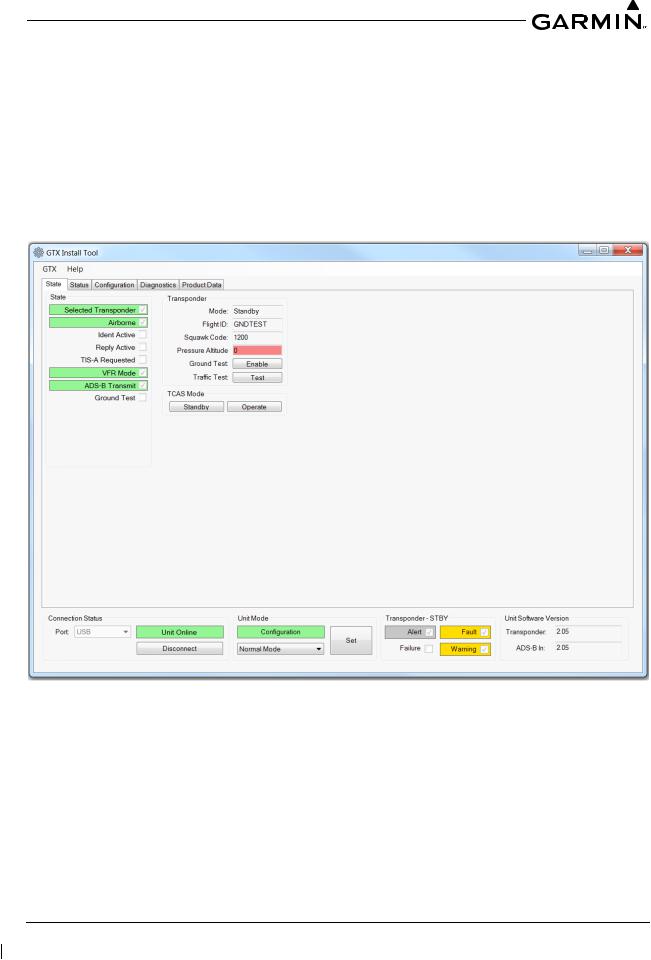
3.3.1State Page
The State page of the GTX 3X5 Install Tool reports the current mode of the GTX 3X5/3X5R, Flight ID, Squawk Code, and PressureAltitude. Mode selections include Ground Test and Traffic Test modes. Standby and Operate test modes are also provided for TCAS.
Figure 3-5 GTX 3X5/3X5R State Page
190-00734-21 |
GTX 3X5 Part 27 AML Maintenance Manual |
Rev. 2 |
Page 3-7 |

3.3.2Status Page
The Status page reports failures, faults, warnings, and pilot alerts. Information such as whether there is a configuration module present is also displayed.
Figure 3-6 GTX 3X5/3X5R Status Page
190-00734-21 |
GTX 3X5 Part 27 AML Maintenance Manual |
Rev. 2 |
Page 3-8 |

3.3.3Configuration Group
The Configuration group contains the following pages:
Aircraft page – allows the configuration of basic aircraft configuration and flight ID settings
Airframe page – allows the configuration of basic airframe configuration and operational options settings
Unit page – allows the configuration of identification code, unit options, and display options
Interfaces page – allows the configuration of serial, A429, discretes, and HSDB settings
Sensors page – allows the configuration of GarminAltitude Encoder, GPS, internalAHRS, and additional sensors
Audio page – allows the configuration of audio options and alerts
Display page – allows the configuration of display and key backlight, photocell and lighting bus curves, and default offsets
NOTE
All configurable settings must match the GTX System Configuration Log retained in the rotorcraft permanent records.
Figure 3-7 GTX 3X5/3X5R Configuration Group
190-00734-21 |
GTX 3X5 Part 27 AML Maintenance Manual |
Rev. 2 |
Page 3-9 |
Loading...