


LifeBook B2545
Table of contents
 Loading...
Fujitsu LifeBook B2545, LifeBook B2566, LifeBook B2562, LifeBook B112, LifeBook B2130 BIOS Guide
...
Main Advanced Security Power Boot Info Exit
Item Specific Help
Fujitsu LifeBook
B Series
This document is
BIOS Guide
LifeBook Series: B Series
Model Numbers: B-2175
Document Date: 10/26/2000
designed to provide
Fujitsu LifeBook
developers and
users with an
understanding of
the system's
Basic Input-Output
System (BIOS)
F1 Help
ESC Exit
Select Item
Select Menu
-/Space Change Values
Enter Select Sub-Menu
▲
F9 Setup Defaults
F10 Save and Exit
FUJITSU PC CORPORATION

LifeBook B Series BIOS
B Series BIOS
BIOS SETUP UTILITY
The BIOS Setup Utility is a program that sets up the
operating environment for your notebook. Your BIOS
is set at the factory for normal operating conditions,
therefore there is no need to set or change the BIOS’ environment to operate your notebook.
The BIOS Setup Utility configures:
• Device control feature parameters, such as changing
I/O addresses and boot devices.
• System Data Security feature parameters, such
as passwords.
Entering the BIOS Setup Utility
To enter the BIOS Setup Utility do the following:
1. Turn on or restart your notebook.
2. Press the [
on the screen. This will open the main menu
of the BIOS Setup Utility with the current
settings displayed.
3. Press the [RIGHT ARROW] or [LEFT ARROW] key
to scroll through the other setup menus to review or
alter the current settings.
Navigating Through The Setup Utility
The BIOS setup utility consists of seven menus; Main,
Advanced, Security, Power, Boot, Info and Exit. This
document explains each menu, including all submenus
and setup items.
The following procedures allow you to navigate the setup
utility menus:
1. To select a menu, use the cursor keys: [ ] [ ] .
2. To select a field within a menu or a submenu, use the
cursor keys: [ ], [ ].
3. To select the different values for each field, press the
Spacebar] or [+] to change to the next higher selec-
[
tion and [
F2] key once the Fujitsu logo appears
F5] or [-] to go to the next lower selection.
4. To activate a submenu press the [Enter] key.
5. To return to a menu from a submenu, press
Esc
] key.
the [
6. To go to the Exit menu from any other menu,
Esc
press the [
POINT
Selecting a field causes a help message about that field
to be displayed on the right-hand side of the screen.
POINT
Pressing the Enter key with the highlight on a selection
that is not a submenu or auto selection will cause a list
of all options for that item to be displayed. Pressing the
Enter key again will select the highlighted choice.
7. Pressing the [
the default values.
8. Pressing the [
tion and exits the BIOS Setup Utility. You will be
asked to verify this selection before it is executed.
9. Pressing the [F1] key gives you a general help screen.
] key.
F9] key resets all items in the BIOS to
F10] key saves the current configura-
Entering the Setup Utility After a Configuration Change or System Failure
If there has been a change in the system configuration
that does not agree with the parameter settings stored
in your BIOS memory, or there is a failure in the system,
the system beeps and/or displays an error message after
the Power On Self Test (POST). If the failure is not
too severe, it will give you the opportunity to modify
the settings of the setup utility, as described in the
following steps:
1. When you turn on or restart the computer there is
a beep and/or the following message appears on
the screen:
Error message - please run SETUP
program Press <F1> key to continue,
<F2> to run SETUP
2
2. If an error message is displayed on the screen, and
you want to continue with the boot process and start
the operating system anyway, press the [F1] key.
CAUTION
If your notebook beeps a series of beeps that sounds
like a code and the display is blank, please refer to the
Troubleshooting Section. The Troubleshooting Section
includes a list of error messages and their meanings.
POINT
If your data security settings require it, you may be
asked for a password before the operating system will
be opened.
3. If an error message is displayed on the screen, and
you want to enter the setup utility, press the [F2] key.
4. When the setup utility starts with a fault present, the
system displays the following message:
Warning!
Error message
[Continue]
5. Press any key to enter the setup utility. The system
will then display the Main Menu with current
parameters values.
B Series BIOS
3
LifeBook B Series BIOS
MAIN MENU – SETTING STANDARD SYSTEM PARAMETERS
The Main Menu allows you to set or view the current
system parameters. Follow the instructions for
Navigating Through The Setup Utility to make any
changes.
The following tables show the names of the menu fields
for the Main menu and its submenus, all of the options
for each field, the default settings and a description of
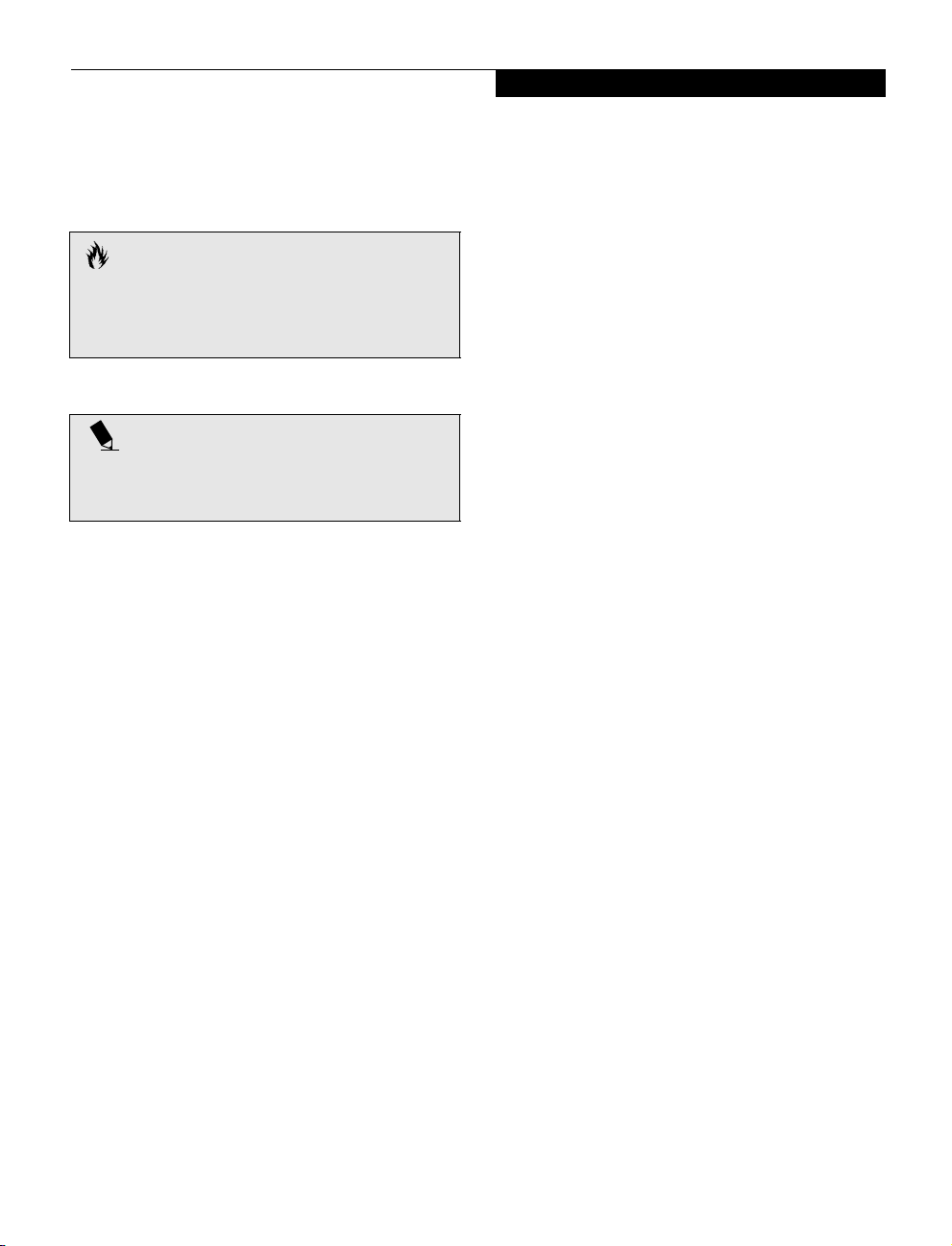
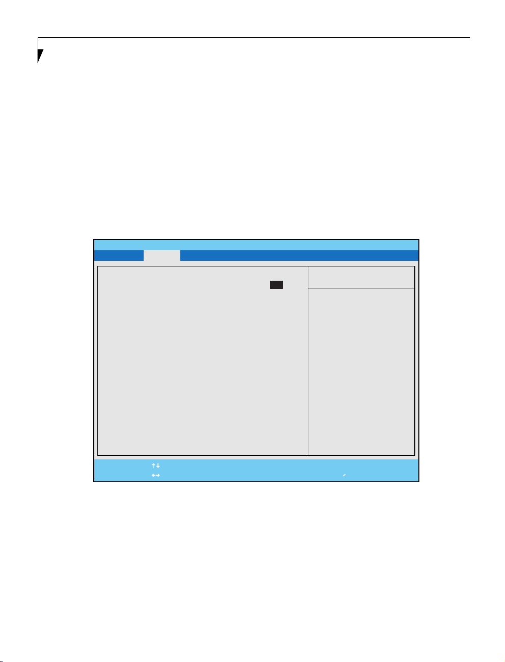
Figure 1. Main Menu
PhoenixBIOS Setup Utility
Main Advanced Security Power Boot Info Exit
System Time: [14:57:01]
System Date: [10/10/2000]
Floppy Disk A: [Disabled]
▲
Primary Master [FUJITSU MHM2100AT-(PM)]
Language: [English (US)]
the field’s function and any special information needed
to help understand the field’s use.
POINT
System Time and System Date can also be set from your
operating system without using the setup utility. Use
the calendar and time icon on your Windows Control
panel or type time or date from the MS-DOS prompt.
Item Specific Help
Adjust calendar clock.
<Tab>, <Shift-Tab>, or
<Enter> selects field.
F1 Help
ESC Exit
Select Item
Select Menu
-/Space Change Values
Enter Select Sub-Menu
▲
F9 Setup Defaults
F10 Save and Exit
Table 1: Fields, Options and Defaults for the Main Menu
Menu Field Options Default Description
System Time: –— –— Sets and displays the current time. Time is in a 24 hour format of
4
hours:minutes:seconds with 2 digits for each. (HH:MM:SS). Example: 16:45:57. You may change each segment of the time
separately. Move between the segments with the [
Shift
Tab
[
] + [
] keys.
Tab
] key and/or

Table 1: Fields, Options and Defaults for the Main Menu
Menu Field Options Default Description
Main Menu
System Date: –— –— Sets and displays the current date. Date is in a month/day/year
Floppy Disk A: • Disabled
Primary Master: • Selects Primary
Language: • English (US)
• 1.44/1.2 MB
3.5"
Master submenu
• Japanese (JP)
[Disabled] Enables or disables floppy disk A.
[Fujitsu
MHM2100AT(PM)]
[English (US)] The default setting differs between the US/European and the Japa-
numeric format with 2 digits each for month and day and 4 digits
for year. (MM/DD/YYYY) for example: 03/20/1998. You may
change each segment of the date separately. Move between the
segments with the [
Displays the type of device on this ATA/ATAPI interface, if there is
one. Pressing the Enter key selects the Primary Master submenu
allowing additional device configuration options for this interface.
nese model. Selects the display language for the BIOS.
Tab] key and/or [Shift] + [Tab] keys.
5
LifeBook B Series BIOS
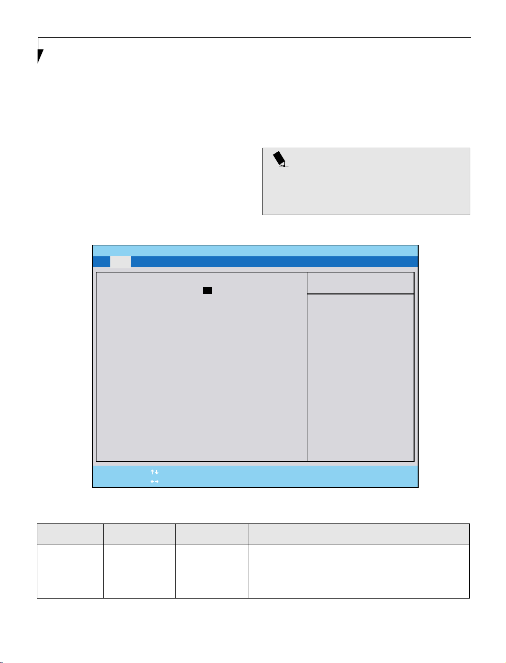
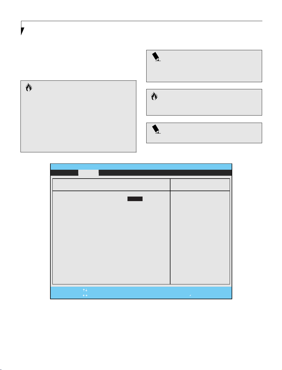
Primary Master Submenu of the Main Menu
The Primary Master submenu identifies what ATA
devices are installed.
PhoenixBIOS Setup Utility
Main Advanced Security Power Boot Info Exit
Primary Master [FUJITSU MHD2032AT]
Type: [Hard Disk]
Cylinders: [16383]
Heads: [16]
Sectors: [63]
Maximum Capacity: 8455MB
Multi-Sector Transfers: [16 Sectors]
LBA Mode Control: [Enabled]
PIO Transfer Mode: [FAST PIO 4]
DMA Transfer Mode: [Ultra DMA 2]
F1 Help
ESC Exit
Select Item
Select Menu
-/Space Change Values
Enter Select Sub-Menu
Note: Actual hard drive label shown may vary. Depending
on the drive type, information such as cylinders, heads and
sectors may also be displayed.
Item Specific Help
Select ATA/ATAPI drive
installed here.
[Auto]
The BIOS auto-types the
drive on boot time.
Except [Auto]
You enter parameters of
the drive.
[None]
The drive is disabled.
▲
F9 Setup Defaults
F10 Save and Exit
Figure 2. Primary Master Submenu
Table 2: Fields, Options and Defaults for the Primary Master Submenu of the Main Menu
Menu Field Options Default Description
Typ e: • Auto
Cylinders: • A number
Heads: • A number
6
• None
• Hard Disk
between 0
and 65,535
between 1
and 16
[Auto] Selects the ATA/ATAPI device type. Select Auto to have the type
–— This item appears only when the type is identifed as Auto or Hard
–— TThis item appears only when the type is identifed as Auto or Hard
automatically identified by the BIOS at POST. If None is selected, all
of the following Set-up items do not appear. If Hard Disk is
selected, you must specify the number of Cylinders, Heads, and
Sectors for the drive. Select ATAPI Removable if a removable disk
drive is installed at this connection.
Disk. When Hard Disk is selected, you can change the value. This
field is changed by incrementing (pressing the [Spacebar]) or by
typing in the number.
Disk. When Hard Disk is selected, you can change the value. This
field is changed by incrementing (pressing the [Spacebar]) or by
typing in the number.

Main Menu
Table 2: Fields, Options and Defaults for the Primary Master Submenu of the Main Menu
Menu Field Options Default Description
Sectors: • A number
Maximum
Capacity:
Multi-Sector
Transfers:
LBA Mode
Control:
PIO Transfer
Mode:
DMA Transfer
Mode:
between 0
and 63
• Display only –— Displays the maximum capacity of the drive calculated from the
• Disabled
• 2 Sectors
• 4 Sectors
• 8 Sectors
• 16 Sectors
• 32 Sectors
• 64 Sectors
• 128 Sectors
• Disabled
• Enabled
• Standard
• Fast PIO 1
• Fast PIO 2
• Fast PIO 3
• Fast PIO 4
• Disabled
• Multiword
DMA 1
• Multiword
DMA 2
• Ultra DMA 0
• Ultra DMA 1
• Ultra DMA 2
–— This item appears only when the type is identifed as Auto or Hard
[16 Sectors] This option cannot be changed when Auto is selected. Specify the
[Enabled] Enables or disables logical Block Addressing in place of Cylinder,
[Fast PI0 4] Selects the method for moving data to/from the drive. Autotype
[Ultra DMA 2] Selects the method for moving data to/from the drive. Autotype
Disk. When Hard Disk is selected, you can change the value. This
field is changed by incrementing (pressing the [Spacebar]) or by
typing in the number.
parameters of the hard disk when Hard Disk is selected.
number of sectors per block for multiple sector transfer.
Head, Sector addressing. This option cannot be changed when
Auto is selected.
the drive to select the optimum transfer mode. This option cannot
be changed when Auto is selected. Multi-word DMA is automatically set to mode 1 for Fast PIO 1, Fast PIO 2, Fast PIO 3, and set to
mode 2 for Fast PIO 4 / DMA.
the drive to select the optimum transfer mode. This option cannot
be changed when Auto is selected.
7
LifeBook B Series BIOS
ADVANCED MENU – SETTING DEVICE FEATURE CONTROLS
The Advanced Menu allows you to:
• Enable or disable support for Plug & Play
operating systems.
• Set the I/O addresses for the serial and parallel ports.
• Set the communication mode for the parallel port and
infrared port.
• Select between the display panel and an external
CRT display.
• Enable or disable compensation for your display.
• Configure PCI devices in your system.
PhoenixBIOS Setup Utility
Main Advanced Security Power Boot Info Exit
Plug & Play O/S: [Yes]
Protected Device Configurations: [No]
▲ ▲ ▲ ▲
Serial/Parallel Port Configurations
Keyboard/Mouse Features
Video Features
Internal Device Configurations
▲
PCI Configurations
▲
USB Features
▲
Event Logging
• Configure USB features.
Follow the instructions for Navigating Through The
Setup Utility to make any changes.
The following tables show the names of the menu fields
for the Advanced Menu and its submenus, all of the
options for each field, the default settings and a description of the field’s function and any special information
needed to help understand the field’s use.
Item Specific Help
[No]
The BIOS configures
also non-boot devices.
Select if you are using
a non-Plug & Play OS or
a non-ACPI OS.
[Yes]
The BIOS configures
only boot devices.
F1 Help
ESC Exit
8
Select Item
Select Menu
-/Space
Enter
Figure 3. Advanced Menu
Change Values
▲
Select Sub-Menu
F9 Setup Defaults
F10 Save and Exit

Table 3: Fields, Options and Defaults for the Advanced Menu
Menu Field Options Default Description
Advanced Menu
Plug & Play O/S: • No
Protected Device
Configuration:
Serial/Parallel Port
Configurations
Keyboard/Mouse
Features
Video Features –— –— When selected, opens the Video Features submenu, which allows
Internal Device
Configurations
PCI Configurations –— –— When selected, opens additional menus to configure PCI devices.
USB Features • Disabled
Event Logging –— –— When selected, opens the event logging submenu.
• Yes
• No
• Yes
–— –— When selected, opens the Serial/Parallel Port Configurations sub-
–— –— When selected, opens the Keyboard/Mouse Features submenu,
–— –— When selected, opens the Internal Device Configurations submenu,
• Enabled
[Yes] Select Yes if you are using a Plug & Play capable operating system.
[No] No: allows Plug & Play operating system to change device
–— Enables and disables the USB Floppy Disk Drive.
Select No if you need the BIOS to configure non-boot devices.
system settings.
Yes: prevents a Plug & Play operating system from changing
system settings.
*ACPI operating system ignores this setting.
menu which allows the user to modify settings for serial, infrared
and parallel ports.
which allows setting external and internal keyboard and
mouse parameters.
setting of the display parameters, including routing of video signals
to different displays.
which allows enabling or disabling the Floppy Disk, IDE, and LAN
Controllers.
9
LifeBook B Series BIOS
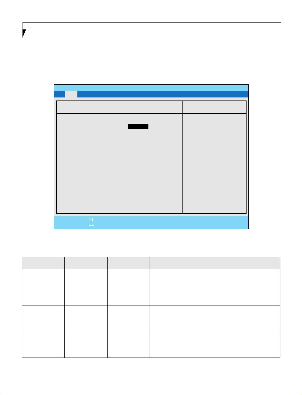
Serial/Parallel Port Configurations Submenu of the Advanced Menu
The Serial/Parallel Port Configurations submenu
provides the ability to set the I/O addresses and
interrupt levels for the serial, infrared and parallel
ports of your notebook.
CAUTION
I/O addresses, DMA channels and Interrupt levels
can be entered in various ways, including via the BIOS
setup utility, the control software for the I/O device,
or the hardware. If any two ports or devices, serial or
parallel, have the same I/O address assigned, your
notebook will not function normally. Please keep a
record of original settings before making any changes
in the event that a restoration is required. See your
hardware and software documentation as well as the
setup utility to determine settings, limitations, etc.
PhoenixBIOS Setup Utility
Advanced
POINT
To prevent IRQ and address conflicts, avoid changing
the default settings. If you must change the settings,
you can call 1-800-8FUJITSU for technical assistance.
CAUTION
The BIOS will warn you of a resource conflict by placing
a yellow asterisk next to each device that is in conflict.
POINT
All I/O addresses in Table 5 are in hexadecimal.
Serial/Parallel Port Configurations
Serial Port: [Enabled]
I/O address: [3F8 - 3FF]
Interrupt: [IRQ 4]
Infrared Port: [Enabled]
Mode: [FIR]
I/O address: [2E8 - 2EF]
Interrupt: [IRQ 3]
I/O address: [118 - 11F]
DMA channel: [DMA 3]
Parallel port: [Enabled]
Mode: [Bi-directional]
I/O address: [378 - 37F]
Interrupt: [IRQ 7]
F1 Help
ESC Exit
Select Item
Select Menu
Figure 4. Serial/Parallel Port Configurations Submenu
-/Space
Enter
Change Values
Select Sub-Menu
Item Specific Help
[Disabled]
The port is disabled.
[Enabled]
The port is enabled
with user configuration.
[Auto]
The port is configured
depending on 'Plug &
Play OS' setting.
▲
F9 Setup Defaults
F10 Save and Exit
10

Table 4: Fields, Options and Defaults for the Serial/Parallel
Port Configurations Submenu of the Advanced Menu
Menu Field Options Default Description
Advanced Menu
Serial Port: • Disabled
I/O Address: • 3F8 - 3FF
Interrupt: • IRQ 3
Infrared Port: • Disabled
Mode: • IrDA
I/O Address: • 3F8-3FF
Interrupt: • IRQ 3
I/O address: • 100 - 107
• Enabled
• Auto
• 2F8 - 2FF
• 3E8 - 3EF
• 2E8 - 2EF
• IRQ 4
• IRQ 5
• Enabled
• Auto
• FIR
• 2F8-2FF
• 3E8 - 3EF
• 2E8 - 2EF
• IRQ 4
• IRQ 5
• 108 - 10F
• 110 - 117
• 118 - 11F
[Enabled] Configures the serial port using either no configuration
[3F8 - 3FF] Allows user to set the serial port base I/O address when serial port
[IRQ 4] Allows user to set the serial port interrupt when serial port
[Enabled] Configures the infrared port using either no configuration
[FIR] When the infrared port is enabled this option is available allowing
[2E8 - 2EF] Allows user to set the infrared port I/O address when the
[IRQ 3] Allows user to set the infrared port interrupt when the infrared
[118 - 11F] Allows user to set the infrared port I/O address when the
(Disabled), a user defined configuration (Enabled), or by
allowing the BIOS or OS to choose the configuration (Auto).
is Enabled.
is Enabled.
(Disabled), a user defined configuration (Enabled), or by
allowing the BIOS or OS to choose the configuration (Auto).
the user to set the mode for the infrared port.
infrared port is Enabled.
port is Enabled.
infrared port is Enabled.
DMA Channel: • DMA 1
Parallel Port: • Disabled
Mode: • Output Only
I/O address: • 378 - 37F
Interrupt: • IRQ 5
• DMA 3
• Enabled
• Auto
• Bi-directional
• ECP
• 278 - 27F
• 3BC - 3BF
• IRQ 7
[DMA 3] Allows user to set the infrared port DMA Channel when the
infrared port is Enabled.
[Enabled] Configures the parallel port using either no configuration
(Disabled), a user defined configuration (Enabled), or by
allowing the BIOS or OS to choose the configuration (Auto).
[Bi-directional] When the parallel port is enabled this option is available allowing
the user to set the mode for the parallel port. Bi-directional allows
two-way transfer of information between your notebook and a
connected parallel device. Output Only (Half Duplex) allows
information to be transferred in only one direction, from your
notebook to the printer or similar device. ECP Mode allows
communication with the ECP class of parallel I/O devices.
[378 - 37F] Allows user to set the parallel port base I/O address when the
parallel port is Enabled.
[IRQ 7] Allows user to set the parallel port interrupt when the parallel
port is Enabled.
11
Loading...