


 Loading...
Fujitsu LifeBook
N Series
BIOS Guide
LifeBook N Series Models:
NH570
Document Date: 02/01/2010
Document Part Number: FPC58-2649-01
F U J I T S U A M E R I C A , I N C .
1

L i f e B o o k N S e r i e s B I O S
N Series BIOS
BIOS SETUP UTILITY
The BIOS Setup Utility is a program that sets up the operating environment for your notebook. Your BIOS is set at the factory for normal operating conditions, therefore there is no need to set or change the BIOS environment to operate your notebook.
The BIOS Setup Utility configures:
■Device control feature parameters, such as changing I/O addresses and boot devices.
■System Data Security parameters, such as passwords.
Entering the BIOS Setup Utility
There are three ways to enter the BIOS Setup Utility: The SecureCore Menu, the [F2] key, or the Boot Menu.
Entering BIOS Setup using the SecureCore Menu
When the Fujitsu logo appears on the screen. press the [Enter] key or click on the left mouse or touchpad button; the SecureCore Menu will appear.
The SecureCore Menu provides shortcuts to the following menus and information screens:
■BIOS Setup
■Diagnostic Screen
■Boot Menu
■Recovery and Utility
■Diagnostic program
■Patent Information
■System Information
■Continue Booting
Click on BIOS Setup to enter the utility.
Entering BIOS Setup using [F2] key
To enter the BIOS Setup Utility using the [F2] key:
1.Turn on or restart your notebook.
2.Press [F2] once the Fujitsu logo appears on the screen. This will open the main menu of the BIOS Setup Utility with the current settings displayed.
Entering BIOS Setup using Boot Menu
To enter the BIOS Setup Utility using the Boot Menu:
1.Turn on or restart your notebook.
2.Press [F12] once the Fujitsu logo appears on the screen. This will open the Boot Menu.
3.Select <Enter BIOS Setup> and click [Enter].
Navigating Through The Setup Utility
The BIOS setup utility consists of six menus: Main, Advanced, Security, Boot, Info, and Exit. This document explains each menu in turn, including all submenus and setup items.
The following procedures allow you to navigate the setup utility menus:
1. To select a menu, use the cursor keys: [ |
|
], [ |
|
]. |
|
|
2.To select a field within a menu or a submenu, use the
cursor keys:
[ ], [ ].
].
3.To select the different values for each field, press the [Spacebar] or [+] to change to the next higher selection and [F5] or [-] to go to the next lower selection.
4.To activate a submenu press the [Enter] key.
5.To return to a menu from a submenu, press the [Esc] key.
6.To go to the Exit menu from any other menu, press the [Esc] key.
■Selecting a field causes a help message about that field to be displayed on the right-hand side of the screen.
■Pressing the Enter key with the highlight on a selection that is not a submenu or auto selection will cause a list of all options for that item to be displayed. Pressing the Enter key again will select the highlighted choice.
7.Pressing the [F9] key resets all items in the BIOS to the default values.
8.Pressing the [F10] key saves the current configuration and exits the BIOS Setup Utility. You will be asked to verify this selection before it is executed.
9.Pressing the [F1] key gives you a general help screen.
2

S e t u p U t i l i t y
Entering the Setup Utility After a Configuration
Change or System Failure
If there has been a change in the system configuration that does not agree with the parameter settings stored in BIOS memory, or there is a failure in the system, the system beeps and/or displays an error message after the Power On Self Test (POST). If the failure is not too severe, it will give you the opportunity to modify the settings of the setup utility, as described in the following steps:
1.When you turn on or restart the computer there is a beep and/or the following message appears on the screen:
Error message - please run SETUP program Press <F1> key to continue, <F2> to run SETUP
2.If an error message is displayed on the screen, and you want to continue with the boot process and start the operating system anyway, press the [F1] key.
■If your notebook emits a series of beeps that sounds like a code and the display is blank, refer to the Troubleshooting section of your system Use’s Guide. The Troubleshooting Section includes a list of error messages and their meanings.
■If your data security settings require it, you may be asked for a password before the operating system will be opened.
3.If an error message is displayed on the screen, and you want to enter the setup utility, press the [F2] key.
4.When the setup utility starts with a fault present, the system displays the following message:
Warning! Error message [Continue]
5.Press any key to enter the setup utility. The system will then display the Main Menu with current parameters values.
3

L i f e B o o k N S e r i e s B I O S
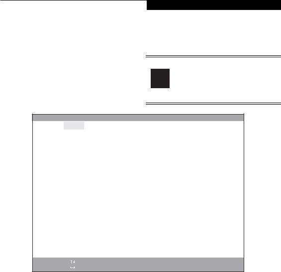
INFO MENU - DISPLAYS BASIC SYSTEM INFORMATION
The Info Menu is a display-only screen that provides the configuration information for your notebook.
The following table shows the names of the menu fields for the Info menu and the information displayed in
those fields. These fields are for information purposes only, and cannot be modified by the user.
The information, including CPU type, speed, and total memory displayed on this screen varies according to the unit you purchased.
|
|
|
Phoenix SecureCore(tm) Setup Utility |
|||||
|
Info |
System |
Advanced |
Security |
Boot |
Exit |
||
|
|
|
|
|
|
|
|
|
|
Product Name: |
|
NH570 |
|
|
|
|
|
|
Serial Number: |
|
XXXXXX |
|
|
|
||
|
BIOS Version: |
|
1.0X |
(XX/XX/2010) |
|
|
|
|
|
Processor Type: |
|
Intel(R) Core(TM) i5 CPU M 430 @ 2.27GHz |
|
||||
|
Total Memory: |
|
4096 |
MB |
|
|
|
|
|
Memory Slot 1: |
|
2048 |
MB DDR3 SDRAM |
|
|
|
|
|
Memory Slot 2: |
|
2048 |
MB DDR3 SDRAM |
|
|
|
|
|
Onboard MAC Address: |
00-XX-XX-XX-XX-XX |
|
|
|
|||
|
UUID: |
|
|
XXXXXXXX-XXXX-XXXX-XXXX-XXXXXXXXXXXX |
|
|||
|
|
|
|
|
|
|
|
|
|
|
|
|
|
|
|
|
|
F1 Help |
Select |
Item |
ESC Exit |
Select |
Menu |
-/Space Change Values
Enter |
Select |
▲ Sub-Menu |
F9 Setup Defaults
F10 Save and Exit
Figure 1. Info Menu
Table 1: Fields, Options and Defaults for the Info Menu
Menu Field |
Default |
Menu Field |
Default |
|
|
|
|
Note that all of the fields on this screen are display only and are for reference.
Note that some the information listed will be different for your system, depending upon the system configuration.
Product Name: |
LifeBook NH570 |
Memory Slot 1: |
2048 MB DDR3 SDRAM |
|
|
|
|
Serial Number: |
Not Defined |
Memory Slot 2: |
2048 MB DDR3 SDRAM |
|
|
|
|
BIOS Version: |
1.XX (XX/XX/2007) |
Onboard MAC Address: |
XX-XX-XX-XX-XX-XX |
|
|
|
|
Processor Type: |
Intel(R) Core(TM) i5 CPU M 430 @ 2.27GHz |
UUID: |
XXXXXXXX-XXXX-XXXX- |
|
|
|
XXXX-XXXXXXXXXXXX |
|
|
|
|
Total Memory: |
4096 MB |
|
|
|
|
|
|
4
S y s t e m M e n u
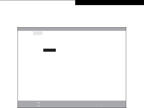
SYSTEM MENU – SETTING STANDARD SYSTEM PARAMETERS
The System Menu allows you to set or view the current system parameters. (See Navigating Through The Setup Utility on page 2 for more information.)
The following tables show the names of the menu fields for the System menu and its submenus, all of the options for each field, the default settings and a description of
the field’s function and any special information needed to help understand the field’s use.
System Time and System Date can also be set from your operating system without using the setup utility. Use the Date and Time icon on your Windows Control panel or type time or date from the command prompt.
|
|
|
|
|
|
|
Phoenix SecureCore(tm) Setup Utility |
|
|||
|
|
|
Info |
System |
|
Advanced |
Security |
Boot |
Exit |
|
|
|
|
|
|
|
|
|
|
|
|
|
|
|
|
|
|
|
|
|
|
|
|
Item Specific Help |
|
|
|
|
|
|
|
|
|
|
|||
|
|
|
System Time: |
[ |
14 |
:57:01] |
|
|
|
|
|
|
|
|
|
|
|
|
|||||
|
|
|
System Date: |
[10/17/2008] |
|
|
|
|
|||
|
|
|
|
|
|
|
|
|
|
Adjust calendar clock. |
|
|
|
▲ Drive0 |
|
[WDC WD3200BEVS-16VAT0] |
|
<Tab>, <Shift-Tab>, or |
|
||||
|
|
▲ Drive1 |
|
[TSSTcorp CDDVDW TS-L633B] |
|
<Enter> selects field. |
|
||||
|
|
▲ |
Drive4 |
|
[None] |
|
|
|
|
||
|
|
▲ |
Drive5 |
|
[None] |
|
|
|
|
||
|
|
|
Language: |
[English (US)] |
|
|
|
|
|||
|
|
|
|
|
|
|
|
|
|
|
|
|
|
|
|
|
|
|
|
|
|
|
|
F1 Help |
Select |
Item |
ESC Exit |
Select |
Menu |
-/Space Change Values
Enter |
Select ▲ |
Sub-Menu |
Figure 2. System Menu
F9 Setup Defaults
F10 Save and Exit
Table 2: Fields, Options and Defaults for the System Menu
Note that the parameters listed in the following table may vary depending upon your system’s configuration.
Menu Field |
Options |
Default |
Description |
|
|
|
|
|
|
|
|
System Time: |
–— |
–— |
Sets and displays the current time. Time is in a 24 hour format |
|
|
|
of hours:minutes:seconds with 2 digits for each. (HH:MM:SS). |
|
|
|
Example: 16:45:57. You may change each segment of the time |
|
|
|
separately. Move between the segments with the [Tab] key and/or |
|
|
|
[Shift] + [Tab] keys. |
|
|
|
|
System Date: |
–— |
–— |
Sets and displays the current date. Date is in a month/day/year |
|
|
|
numeric format with 2 digits each for month and day and 4 digits for |
|
|
|
year. (MM/DD/YYYY) for example: 03/20/2007. You may |
|
|
|
change each segment of the date separately. Move between the |
|
|
|
segments with the [Tab] key and/or [Shift] + [Tab] keys. |
|
|
|
|
5

L i f e B o o k N S e r i e s B I O S
Table 2: Fields, Options and Defaults for the System Menu
Note that the parameters listed in the following table may vary depending upon your system’s configuration.
Menu Field |
Options |
Default |
Description |
|
|
|
|
|
|
|
|
|
|
|
Drive0 |
Selects the Drive0 |
The product |
Display the type of device on this ATA/IDE interface. Pressing the |
|
|
Serial ATA drive |
number of the hard |
Enter key selects the Serial ATA Drive0 submenu allowing additional |
|
|
submenu |
drive. |
device configuration options for this interface. |
|
|
|
|
|
|
Drive1: |
Selects the Drive1 |
The product |
Display the type of device on this ATA/IDE interface, if there is one. |
|
|
Serial ATA drive |
number of the |
Pressing the Enter key selects the Serial ATA Drive1 submenu allow- |
|
|
submenu |
optical drive. |
ing additional device configuration options for this interface. |
|
|
|
|
|
|
Drive4 |
Selects the Drive4 |
The product |
Display the type of device on this e-SATA interface. Pressing the |
|
|
e-ATA drive sub- |
number of the e- |
Enter key selects the e-SATA Drive4 submenu allowing additional |
|
|
menu |
SATA drive. |
device configuration options for this interface. |
|
|
|
|
|
|
Drive5: |
Selects the Drive5 |
The product |
Display the type of device on this interface, if there is one. Pressing |
|
|
2nd hard disk drive |
number of the |
the Enter key selects the Drive5 submenu allowing additional device |
|
|
submenu |
2nd hard disk drive. |
configuration options for this interface. |
|
|
|
|
|
|
Language: |
■ |
English (US) |
[English (US)] |
The default setting differs between the US and the Japanese model. |
|
■ |
Japanese (JP) |
|
Selects the display language for the BIOS. |
|
|
|
|
|
6
S y s t e m M e n u
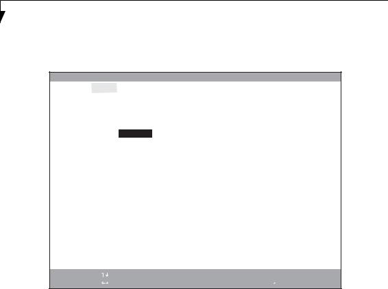
Drive0 Submenu of the System Menu
The Drive0 submenu identifies what ATA devices are installed.
|
|
|
Phoenix SecureCore(tm) Setup Utility |
||||
|
Info |
System |
Advanced |
Security |
Boot |
Exit |
|
|
|
|
|
|
|
||
|
|
Drive0 [WDC WD3200BEVS-16VAT0] |
|
Item Specific Help |
|
||
|
|
|
|
|
|
|
|
|
Drive0: |
|
[Enabled]] |
|
|
[Disabled] |
|
|
|
|
|
|
|
The drive is disabled. |
|
|
Type: |
|
Hard Disk |
|
|
|
|
|
Model: |
|
WDC WD3200BEVS-16VAT0 |
|
[Enabled] |
|
|
|
Capacity: |
|
320GB |
|
|
The drive is enabled. |
|
|
|
|
(320,072,933,376 Bytes) |
|
|
|
|
|
|
|
|
|
|
|
|
|
|
|
|
|
|
|
|
F1 |
Help |
Select |
Item |
-/Space |
Change |
Values |
ESC |
Exit |
Select |
Menu |
Enter |
Select |
▲ Sub-Menu |
Figure 3. Drive0 Master Submenu
F9 Setup Defaults
F10 Save and Exit
Table 3: Fields, Options and Defaults for the Drive0 Submenu of the System Menu
Menu Field |
Options |
Default |
Description |
|
|
|
|
|
|
|
|
|
|
|
Drive0: |
■ |
Disabled |
[Enabled] |
Enables and disables Drive0. |
|
■ |
Enabled |
|
|
|
|
|
|
|
Type: |
--- |
--- |
The type of drive represented by Drive0. |
|
|
|
|
|
|
Model: |
--- |
--- |
The model of the Drive0 drive. |
|
|
|
|
|
|
Capacity: |
--- |
--- |
The maximum capacity of your hard disk |
|
|
|
|
|
|
7
L i f e B o o k N S e r i e s B I O S
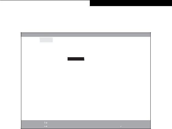
Drive1 Submenu of the System Menu
The Drive1 submenu allows you to configure secondary ATA devices.
|
|
|
Phoenix SecureCore(tm) Setup Utility |
||||
|
Info |
System |
Advanced |
Security |
Boot |
Exit |
|
|
|
|
|
|
|
||
|
|
Drive1 [TSSTcorp CDCVDW TS-L633B] |
|
Item Specific Help |
|
||
|
|
|
|
|
|
|
|
|
Drive1: |
|
[Enabled]] |
|
|
[Disabled] |
|
|
|
|
|
|
|
The drive is disabled. |
|
|
Type: |
|
CD/DVD |
|
|
|
|
|
Model: |
|
TSSTcorp CDCVDW TS-L633B |
|
[Enabled] |
|
|
|
|
|
|
|
|
The drive is enabled. |
|
|
|
|
|
|
|
|
|
|
|
|
|
|
|
|
|
F1 |
Help |
Select |
Item |
-/Space Change |
Values |
|
ESC |
Exit |
Select |
Menu |
Enter |
Select |
▲ Sub-Menu |
|
|
|
|
Figure 4. |
Drive1 Submenu |
|
F9 Setup Defaults
F10 Save and Exit
Table 4: Fields, Options and Defaults for the Drive1 Submenu of the System Menu
Menu Field |
Options |
Default |
Description |
|
|
|
|
|
|
|
|
|
|
|
Drive1: |
■ |
Disabled |
[Enabled] |
Enables and disables Drive1. |
|
■ |
Enabled |
|
|
|
|
|
|
|
Type: |
--- |
--- |
The type of drive represented by Drive1. |
|
|
|
|
|
|
Model: |
--- |
--- |
The model of the Drive1 drive. |
|
|
|
|
|
|
Exiting from System Menu
When you have finished setting the parameters on this menu, you can either exit from the setup utility, or move to another menu. If you wish to exit from the setup utility, press the [Esc] key or use the cursor keys to go to the Exit menu. If you wish to move to another menu, use the cursor keys.
8
S y s t e m M e n u
Drive4 Submenu of the System Menu
The Drive4 submenu identifies what ATA devices are installed.
|
|
|
Phoenix TrustedCore(tm) Setup Utility |
||||
|
Info |
System |
Advanced |
Security |
Boot |
Exit |
|
|
|
|
|
|
|
|
|
|
|
|
|
|
|
|
|
|
|
Drive4 [None] |
|
|
Item Specific Help |
|
|
|
|
|
|
|
|
|
|
|
|
|
|
|
|
|
|
|
Drive4: |
|
[Enabled] |
|
[Disabled] |
|
|
|
Type: |
|
None |
|
|
The drive is disabled. |
|
|
|
|
|
|
|
||
|
|
|
|
|
|
[Enabled] |
|
|
|
|
|
|
|
The drive is enabled. |
|
|
|
|
|
|
|
|
|
|
|
|
|
|
|
|
|
F1 |
Help |
Select |
Item |
-/Space |
Change |
Values |
ESC |
Exit |
Select |
Menu |
Enter |
Select |
▲ Sub-Menu |
Figure 5. Drive4 Master Submenu
F9 Setup Defaults
F10 Save and Exit
Table 5: Fields, Options and Defaults for the Drive4 Submenu of the System Menu
Menu Field |
Options |
Default |
Description |
|
|
|
|
|
|
|
|
|
|
|
Drive4: |
■ |
Disabled |
[Enabled] |
Enables and disables Drive4. |
|
■ |
Enabled |
|
|
|
|
|
|
|
Type: |
--- |
--- |
The type of drive represented by Drive4. |
|
|
|
|
|
|
Model: |
--- |
--- |
The model of the Drive4 drive. (This field is only present when the device is |
|
|
|
|
|
present). |
|
|
|
|
|
Capacity: |
--- |
--- |
The maximum capacity of your hard disk. (This field is only present when |
|
|
|
|
|
the device is present). |
|
|
|
|
|
9
Loading...