


 Loading...

SPARC Enterprise™
M4000/M5000 Servers
Service Manual
Manual Code C120-E352-06EN
Part No. 819-7903-13
August 2009, Revision A

Copyright 2007-2009 Sun Microsystems, Inc., 4150 Network Circle, Santa Clara, California 95054, U.S.A. All rights reserved.
FUJITSU LIMITED provided technical input and review on portions of this material.
Sun Microsystems, Inc. and Fujitsu Limited each own or control intellectual property rights relating to products and technology described in this document, and such products, technology and this document are protected by copyright laws, patents and other intellectual property laws and international treaties. The intellectual property rights of Sun Microsystems, Inc. and Fujitsu Limited in such products, technology and this document include, without limitation, one or more of the United States patents listed at http://www.sun.com/patents and one or more additional patents or patent applications in the United States or other countries.
This document and the product and technology to which it pertains are distributed under licenses restricting their use, copying, distribution, and decompilation. No part of such product or technology, or of this document, may be reproduced in any form by any means without prior written authorization of Fujitsu Limited and Sun Microsystems, Inc., and their applicable licensors, if any. The furnishing of this document to you does not give you any rights or licenses, express or implied, with respect to the product or technology to which it pertains, and this document does not contain or represent any commitment of any kind on the part of Fujitsu Limited or Sun Microsystems, Inc., or any affiliate of either of them.
This document and the product and technology described in this document may incorporate third-party intellectual property copyrighted by and/or licensed from suppliers to Fujitsu Limited and/or Sun Microsystems, Inc., including software and font technology.
Per the terms of the GPL or LGPL, a copy of the source code governed by the GPL or LGPL, as applicable, is available upon request by the End User. Please contact Fujitsu Limited or Sun Microsystems, Inc.
This distribution may include materials developed by third parties.
Parts of the product may be derived from Berkeley BSD systems, licensed from the University of California. UNIX is a registered trademark in the U.S. and in other countries, exclusively licensed through X/Open Company, Ltd.
Sun, Sun Microsystems, the Sun logo, Java, Netra, Solaris, Sun Ray, Answerbook2, docs.sun.com, OpenBoot, and Sun Fire are trademarks or registered trademarks of Sun Microsystems, Inc., or its subsidiaries, in the U.S. and other countries.
Fujitsu and the Fujitsu logo are registered trademarks of Fujitsu Limited.
All SPARC trademarks are used under license and are registered trademarks of SPARC International, Inc. in the U.S. and other countries. Products bearing SPARC trademarks are based upon architecture developed by Sun Microsystems, Inc.
SPARC64 is a trademark of SPARC International, Inc., used under license by Fujitsu Microelectronics, Inc. and Fujitsu Limited.
The OPEN LOOK and Sun™ Graphical User Interface was developed by Sun Microsystems, Inc. for its users and licensees. Sun acknowledges the pioneering efforts of Xerox in researching and developing the concept of visual or graphical user interfaces for the computer industry. Sun holds a non-exclusive license from Xerox to the Xerox Graphical User Interface, which license also covers Sun’s licensees who implement OPEN LOOK GUIs and otherwise comply with Sun’s written license agreements.
United States Government Rights - Commercial use. U.S. Government users are subject to the standard government user license agreements of Sun Microsystems, Inc. and Fujitsu Limited and the applicable provisions of the FAR and its supplements.
Disclaimer: The only warranties granted by Fujitsu Limited, Sun Microsystems, Inc. or any affiliate of either of them in connection with this document or any product or technology described herein are those expressly set forth in the license agreement pursuant to which the product or technology is provided. EXCEPT AS EXPRESSLY SET FORTH IN SUCH AGREEMENT, FUJITSU LIMITED, SUN MICROSYSTEMS, INC. AND THEIR AFFILIATES MAKE NO REPRESENTATIONS OR WARRANTIES OF ANY KIND (EXPRESS OR IMPLIED) REGARDING SUCH PRODUCT OR TECHNOLOGY OR THIS DOCUMENT, WHICH ARE ALL PROVIDED AS IS, AND ALL EXPRESS OR IMPLIED CONDITIONS, REPRESENTATIONS AND WARRANTIES, INCLUDING WITHOUT LIMITATION ANY IMPLIED WARRANTY OF MERCHANTABILITY, FITNESS FOR A PARTICULAR PURPOSE OR NON-INFRINGEMENT, ARE DISCLAIMED, EXCEPT TO THE EXTENT THAT SUCH DISCLAIMERS ARE HELD TO BE LEGALLY INVALID. Unless otherwise expressly set forth in such agreement, to the extent allowed by applicable law, in no event shall Fujitsu Limited, Sun Microsystems, Inc. or any of their affiliates have any liability to any third party under any legal theory for any loss of revenues or profits, loss of use or data, or business interruptions, or for any indirect, special, incidental or consequential damages, even if advised of the possibility of such damages.
DOCUMENTATION IS PROVIDED “AS IS” AND ALL EXPRESS OR IMPLIED CONDITIONS, REPRESENTATIONS AND WARRANTIES, INCLUDING ANY IMPLIED WARRANTY OF MERCHANTABILITY, FITNESS FOR A PARTICULAR PURPOSE OR NON-INFRINGEMENT, ARE DISCLAIMED, EXCEPT TO THE EXTENT THAT SUCH DISCLAIMERS ARE HELD TO BE LEGALLY INVALID.
Please
Recycle
Copyright 2007-2009 Sun Microsystems, Inc., 4150 Network Circle, Santa Clara, California 95054, Etats-Unis. Tous droits réservés.
Entrée et revue tecnical fournies par FUJITSU LIMITED sur des parties de ce matériel.
Sun Microsystems, Inc. et Fujitsu Limited détiennent et contrôlent toutes deux des droits de propriété intellectuelle relatifs aux produits et technologies décrits dans ce document. De même, ces produits, technologies et ce document sont protégés par des lois sur le copyright, des brevets, d’autres lois sur la propriété intellectuelle et des traités internationaux. Les droits de propriété intellectuelle de Sun Microsystems, Inc. et Fujitsu Limited concernant ces produits, ces technologies et ce document comprennent, sans que cette liste soit exhaustive, un ou plusieurs des brevets déposés aux États-Unis et indiqués à l’adresse http://www.sun.com/patents de même qu’un ou plusieurs brevets ou applications brevetées supplémentaires aux États-Unis et dans d’autres pays.
Ce document, le produit et les technologies afférents sont exclusivement distribués avec des licences qui en restreignent l’utilisation, la copie, la distribution et la décompilation. Aucune partie de ce produit, de ces technologies ou de ce document ne peut être reproduite sous quelque forme que ce soit, par quelque moyen que ce soit, sans l’autorisation écrite préalable de Fujitsu Limited et de Sun Microsystems, Inc., et de leurs éventuels bailleurs de licence. Ce document, bien qu’il vous ait été fourni, ne vous confère aucun droit et aucune licence, expresses ou tacites, concernant le produit ou la technologie auxquels il se rapporte. Par ailleurs, il ne contient ni ne représente aucun engagement, de quelque type que ce soit, de la part de Fujitsu Limited ou de Sun Microsystems, Inc., ou des sociétés affiliées.
Ce document, et le produit et les technologies qu’il décrit, peuvent inclure des droits de propriété intellectuelle de parties tierces protégés par copyright et/ou cédés sous licence par des fournisseurs à Fujitsu Limited et/ou Sun Microsystems, Inc., y compris des logiciels et des technologies relatives aux polices de caractères.
Par limites du GPL ou du LGPL, une copie du code source régi par le GPL ou LGPL, comme applicable, est sur demande vers la fin utilsateur disponible; veuillez contacter Fujitsu Limted ou Sun Microsystems, Inc.
Cette distribution peut comprendre des composants développés par des tierces parties.
Des parties de ce produit pourront être dérivées des systèmes Berkeley BSD licenciés par l’Université de Californie. UNIX est une marque déposée aux Etats-Unis et dans d’autres pays et licenciée exclusivement par X/Open Company, Ltd.
Sun, Sun Microsystems, le logo Sun, Java, Netra, Solaris, Sun Ray, Answerbook2, docs.sun.com, OpenBoot, et Sun Fire sont des marques de fabrique ou des marques déposées de Sun Microsystems, Inc., ou ses filiales, aux Etats-Unis et dans d’autres pays.
Fujitsu et le logo Fujitsu sont des marques déposées de Fujitsu Limited.
Toutes les marques SPARC sont utilisées sous licence et sont des marques de fabrique ou des marques déposées de SPARC International, Inc. aux Etats-Unis et dans d’autres pays. Les produits portant les marques SPARC sont basés sur une architecture développée par Sun Microsystems, Inc.
SPARC64 est une marques déposée de SPARC International, Inc., utilisée sous le permis par Fujitsu Microelectronics, Inc. et Fujitsu Limited.
L’interface d’utilisation graphique OPEN LOOK et Sun™ a été développée par Sun Microsystems, Inc. pour ses utilisateurs et licenciés. Sun reconnaît les efforts de pionniers de Xerox pour la recherche et le développement du concept des interfaces d’utilisation visuelle ou graphique pour l’industrie de l’informatique. Sun détient une license non exclusive de Xerox sur l’interface d’utilisation graphique Xerox, cette licence couvrant également les licenciés de Sun qui mettent en place l’interface d’utilisation graphique OPEN LOOK et qui, en outre, se conforment aux licences écrites de Sun.
Droits du gouvernement américain - logiciel commercial. Les utilisateurs du gouvernement américain sont soumis aux contrats de licence standard de Sun Microsystems, Inc. et de Fujitsu Limited ainsi qu’aux clauses applicables stipulées dans le FAR et ses suppléments.
Avis de non-responsabilité: les seules garanties octroyées par Fujitsu Limited, Sun Microsystems, Inc. ou toute société affiliée de l’une ou l’autre entité en rapport avec ce document ou tout produit ou toute technologie décrit(e) dans les présentes correspondent aux garanties expressément stipulées dans le contrat de licence régissant le produit ou la technologie fourni(e). SAUF MENTION CONTRAIRE EXPRESSÉMENT STIPULÉE DANS CE CONTRAT, FUJITSU LIMITED, SUN MICROSYSTEMS, INC. ET LES SOCIÉTÉS AFFILIÉES REJETTENT TOUTE REPRÉSENTATION OU TOUTE GARANTIE, QUELLE QU’EN SOIT LA NATURE (EXPRESSE OU IMPLICITE) CONCERNANT CE PRODUIT, CETTE TECHNOLOGIE OU CE DOCUMENT, LESQUELS SONT FOURNIS EN L’ÉTAT. EN OUTRE, TOUTES LES CONDITIONS, REPRÉSENTATIONS ET GARANTIES EXPRESSES OU TACITES, Y COMPRIS NOTAMMENT TOUTE GARANTIE IMPLICITE RELATIVE À LA QUALITÉ MARCHANDE, À L’APTITUDE À UNE UTILISATION PARTICULIÈRE OU À L’ABSENCE DE CONTREFAÇON, SONT EXCLUES, DANS LA MESURE AUTORISÉE PAR LA LOI APPLICABLE. Sauf mention contraire expressément stipulée dans ce contrat, dans la mesure autorisée par la loi applicable, en aucun cas Fujitsu Limited, Sun Microsystems, Inc. ou l’une de leurs filiales ne sauraient être tenues responsables envers une quelconque partie tierce, sous quelque théorie juridique que ce soit, de tout manque à gagner ou de perte de profit, de problèmes d’utilisation ou de perte de données, ou d’interruptions d’activités, ou de tout dommage indirect, spécial, secondaire ou consécutif, même si ces entités ont été préalablement informées d’une telle éventualité.
LA DOCUMENTATION EST FOURNIE “EN L’ETAT” ET TOUTES AUTRES CONDITIONS, DECLARATIONS ET GARANTIES EXPRESSES OU TACITES SONT FORMELLEMENT EXCLUES, DANS LA MESURE AUTORISEE PAR LA LOI APPLICABLE, Y COMPRIS NOTAMMENT TOUTE GARANTIE IMPLICITE RELATIVE A LA QUALITE MARCHANDE, A L’APTITUDE A UNE UTILISATION PARTICULIERE OU A L’ABSENCE DE CONTREFACON.

Contents
Preface xvii
1. Safety and Tools 1–1
1.1Safety Precautions 1–1
1.2System Precautions 1–2
1.2.1 |
Electrical Safety Precautions |
1–2 |
1.2.2 |
Equipment Rack Safety Precautions 1–2 |
|
1.2.3 |
Filler Boards and Filler Panels |
1–3 |
1.2.4Handling Components 1–3
2.Fault Isolation 2–1
2.1 |
Determining Which Diagnostics Tools to Use 2–1 |
|
|||
2.2 |
Checking the Server and System Configuration |
2–4 |
|
||
|
2.2.1 |
Checking the Hardware Configuration and FRU Status 2–4 |
|||
|
|
2.2.1.1 |
Checking the Hardware Configuration |
2–5 |
|
|
2.2.2 |
Checking the Software and Firmware Configuration 2–6 |
|||
|
|
2.2.2.1 |
Checking the Software Configuration |
2–7 |
|
|
|
2.2.2.2 |
Checking the Firmware Configuration |
2–7 |
|
|
2.2.3 Downloading the Error Log Information |
2–8 |
|
||
2.3 |
Operator Panel |
2–9 |
|
|
|
v
2.4Error Conditions 2–14
2.4.1 |
Predictive Self-Healing Tools 2–14 |
2.4.2Monitoring Output 2–17
2.4.3Messaging Output 2–17
2.5LED Functions 2–18
2.6 Using the Diagnostic Commands 2–21
2.6.1 |
Using the showlogs Command 2–21 |
||||
2.6.2 |
Using the fmdump Command 2–22 |
|
|||
|
2.6.2.1 |
fmdump |
-V |
Command |
2–22 |
|
2.6.2.2 |
fmdump |
-e |
Command |
2–23 |
2.6.3 Using the fmadm faulty Command 2–23
2.6.3.1fmadm repair Command 2–23
2.6.3.2fmadm config Command 2–24
2.6.4 |
Using the fmstat Command |
2–24 |
||
2.7 Traditional Solaris Diagnostic Commands 2–26 |
||||
2.7.1 |
Using the iostat Command |
2–27 |
||
|
2.7.1.1 |
Options |
2–27 |
|
2.7.2 |
Using the prtdiag Command |
2–28 |
||
|
2.7.2.1 |
Options |
2–28 |
|
2.7.3 |
Using the prtconf Command |
2–30 |
||
|
2.7.3.1 |
Options |
2–30 |
|
2.7.4 |
Using the netstat Command |
2–32 |
||
|
2.7.4.1 |
Options |
2–33 |
|
2.7.5 Using the ping Command 2–34
2.7.5.1Options 2–34
2.7.6 Using the ps Command 2–35
2.7.6.1Options 2–35
2.7.7 Using the prstat Command 2–36
vi SPARC Enterprise M4000/M5000 Servers Service Manual • August 2009
2.7.7.1Options 2–36
2.8Other Issues 2–37
2.8.1 |
Can’t Locate Boot Device 2–37 |
3.Periodic Maintenance 3–1
3.1 |
Tape Drive Unit 3–1 |
|
|
3.1.1 Cleaning the Tape Drive Unit 3–1 |
|
4. FRU Replacement Preparation |
4–1 |
|
4.1 |
FRU Replacement Method |
4–1 |
4.2Active Replacement 4–4
4.2.1 |
Removing a FRU From a Domain |
4–4 |
|
4.2.2 |
Removing and Replacing a FRU |
4–5 |
|
4.2.3 |
Adding a FRU Into a Domain |
4–5 |
|
4.2.4 |
Verifying Hardware Operation |
4–6 |
|
4.3Hot Replacement 4–6
|
4.3.1 |
Removing and Replacing a FRU |
4–7 |
|
|
|
|
4.3.2 |
Verifying Hardware Operation |
4–9 |
|
|
|
4.4 |
Cold Replacement (Powering the Server Off and On) |
4–12 |
||||
|
4.4.1 |
Powering the Server Off Using Software |
4–12 |
|
||
|
4.4.2 |
Powering the Server On Using Software |
4–13 |
|
||
|
4.4.3 |
Powering the Server Off Manually |
4–14 |
|
|
|
|
4.4.4 |
Powering the Server On Manually |
4–14 |
|
|
|
|
4.4.5 |
Verifying Hardware Operation |
4–15 |
|
|
|
5. Internal Components Access 5–1 |
|
|
|
|
||
5.1 |
Sliding the Server In and Out to the Fan Stop 5–1 |
|
||||
|
5.1.1 |
Sliding the Server Out of the Equipment Rack |
5–2 |
|||
|
5.1.2 |
Sliding the Server Into the Equipment Rack 5–4 |
||||
5.2 |
Top Cover Remove and Replace 5–5 |
|
|
|
|
|
Contents vii
5.2.1 |
Removing the Top Cover |
5–5 |
|
5.2.2 |
Replacing the Top Cover |
5–8 |
|
5.3 Fan Cover Remove and Replace |
5–8 |
|
|
5.3.1 |
Removing the Fan Cover |
5–8 |
|
5.3.2 |
Replacing the Fan Cover |
5–10 |
|
6. Storage Devices Replacement 6–1 |
|
|
|
6.1 Hard Disk Drive Replacement 6–1 |
|
||
6.1.1 |
Accessing the Hard Disk Drive |
6–4 |
|
6.1.2 |
Removing the Hard Disk Drive |
6–4 |
|
6.1.3 |
Installing the Hard Disk Drive |
6–5 |
|
6.1.4 |
Securing the Server 6–5 |
|
|
6.1.5Accessing the Hard Disk Drive Backplane of the SPARC Enterprise M4000 Server 6–6
6.1.6Removing the Hard Disk Drive Backplane of the SPARC Enterprise M4000 Server 6–6
6.1.7Installing the Hard Disk Drive Backplane of the SPARC Enterprise M4000 Server 6–7
6.1.8 |
Securing the Server 6–8 |
6.1.9Accessing the Hard Disk Drive Backplane of the SPARC Enterprise M5000 Server 6–9
6.1.10Removing the Hard Disk Drive Backplane of the SPARC Enterprise M5000 Server 6–10
6.1.11Installing the Hard Disk Drive Backplane of the SPARC Enterprise M5000 Server 6–10
6.1.12 |
Securing the Server 6–11 |
|
6.2 CD-RW/DVD-RW Drive Unit (DVDU) Replacement |
6–12 |
|
6.2.1 |
Accessing the CD-RW/DVD-RW Drive Unit |
6–15 |
6.2.2 |
Removing the CD-RW/DVD-RW Drive Unit |
6–15 |
6.2.3 |
Installing the CD-RW/DVD-RW Drive Unit |
6–16 |
6.2.4 |
Securing the Server 6–16 |
|
viii SPARC Enterprise M4000/M5000 Servers Service Manual • August 2009
6.2.5Accessing the CD-RW/DVD-RW Drive Backplane of the SPARC
Enterprise M4000 Server 6–17
6.2.6Removing the CD-RW/DVD-RW Drive Backplane of the SPARC
Enterprise M4000 Server 6–17
6.2.7Installing the CD-RW/DVD-RW Drive Backplane of the SPARC
|
Enterprise M4000 Server 6–18 |
6.2.8 |
Securing the Server 6–18 |
6.2.9Accessing the CD-RW/DVD-RW Drive Backplane of the SPARC
Enterprise M5000 Server 6–19
6.2.10Removing the CD-RW/DVD-RW Drive Backplane of the SPARC
Enterprise M5000 Server 6–20
6.2.11Installing the CD-RW/DVD-RW Drive Backplane of the SPARC
|
|
Enterprise M5000 Server 6–20 |
|
|
|
6.2.12 |
Securing the Server |
6–21 |
|
6.3 |
Tape Drive Unit Replacement |
6–22 |
|
|
|
6.3.1 |
Accessing the Tape Drive Unit |
6–25 |
|
|
6.3.2 |
Removing the Tape Drive Unit |
6–25 |
|
|
6.3.3 |
Installing the Tape Drive Unit |
6–26 |
|
|
6.3.4 |
Securing the Server |
6–26 |
|
6.3.5Accessing the Tape Drive Backplane of the SPARC Enterprise M4000 Server 6–27
6.3.6Removing the Tape Drive Backplane of the SPARC Enterprise M4000 Server 6–28
6.3.7Installing the Tape Drive Backplane of the SPARC Enterprise M4000 Server 6–28
6.3.8 |
Securing the Server 6–29 |
6.3.9Accessing the Tape Drive Backplane of the SPARC Enterprise M5000 Server 6–30
6.3.10Removing the Tape Drive Backplane of the SPARC Enterprise M5000 Server 6–31
6.3.11Installing the Tape Drive Backplane of the SPARC Enterprise M5000 Server 6–31
6.3.12 Securing the Server 6–32
Contents ix
7. Power Systems Replacement 7–1 |
|
|
7.1 Power Supply Unit Replacement 7–1 |
|
|
7.1.1 |
Accessing the Power Supply Unit |
7–4 |
7.1.2 |
Removing the Power Supply Unit |
7–4 |
7.1.3 |
Installing the Power Supply Unit |
7–5 |
7.1.4 |
Securing the Server 7–5 |
|
8. I/O Unit Replacement 8–1 |
|
|
|
|
||
8.1 |
PCI Cassette Replacement |
8–4 |
|
|
||
|
8.1.1 |
Accessing the PCI Cassette |
8–5 |
|||
|
8.1.2 |
Removing the PCI Cassette |
8–5 |
|||
|
8.1.3 |
Installing the PCI Cassette |
8–6 |
|||
|
8.1.4 |
Securing the Server |
8–7 |
|
||
8.2 |
PCI Card Replacement |
8–7 |
|
|
|
|
|
8.2.1 |
Removing the PCI Card |
8–7 |
|||
|
8.2.2 |
Installing the PCI Card |
8–8 |
|
||
8.3 |
I/O Unit Replacement |
8–10 |
|
|
||
|
8.3.1 |
Accessing the I/O Unit |
8–10 |
|||
|
8.3.2 |
Removing the I/O Unit |
8–10 |
|||
|
8.3.3 |
Installing the I/O Unit |
8–11 |
|||
|
8.3.4 |
Securing the Server |
8–12 |
|
||
8.4 |
I/O Unit DC-DC Converter Replacement 8–12 |
|||||
8.4.1Accessing the I/O Unit DC-DC Converter (DDC_A#0 or DDC_B#0) 8–14
8.4.2Removing the I/O Unit DC-DC Converter (DDC_A #0 or DDC_B #0) 8–14
8.4.3Installing the I/O Unit DC-DC Converter (DDC_A #0 or DDC_B #0) 8–17
8.4.4 |
Securing the Server 8–21 |
8.4.5 |
Accessing the I/O Unit DC-DC Converter Riser 8–21 |
x SPARC Enterprise M4000/M5000 Servers Service Manual • August 2009
|
|
8.4.6 |
Removing the I/O Unit DC-DC Converter Riser |
8–22 |
||||
|
|
8.4.7 |
Replacing the I/O Unit DC-DC Converter Riser |
8–24 |
||||
|
|
8.4.8 |
Securing the Server |
8–24 |
|
|
|
|
9. |
XSCF Unit Replacement 9–1 |
|
|
|
|
|
||
|
9.1 |
XSCF Unit Replacement 9–1 |
|
|
|
|
||
|
|
9.1.1 |
Accessing the XSCF Unit |
9–3 |
|
|
|
|
|
|
9.1.2 |
Removing the XSCF Unit |
9–4 |
|
|
|
|
|
|
9.1.3 |
Installing the XSCF Unit |
9–5 |
|
|
|
|
|
|
9.1.4 |
Securing the Server |
9–5 |
|
|
|
|
10. |
Fan Modules Replacement 10–1 |
|
|
|
|
|
||
|
10.1 |
Fan Module Replacement |
10–1 |
|
|
|
|
|
|
|
10.1.1 |
Accessing the 60-mm Fan Module |
10–4 |
|
|||
|
|
10.1.2 |
Removing the 60-mm Fan Module |
10–5 |
|
|||
|
|
10.1.3 |
Installing the 60-mm Fan Module |
10–6 |
|
|||
|
|
10.1.4 |
Securing the Server |
10–6 |
|
|
|
|
|
|
10.1.5 |
Accessing the 172-mm Fan Module |
|
10–7 |
|
||
|
|
10.1.6 |
Removing the 172-mm Fan Module |
|
10–8 |
|
||
|
|
10.1.7 |
Installing the 172-mm Fan Module |
|
10–9 |
|
||
|
|
10.1.8 |
Securing the Server |
10–9 |
|
|
|
|
|
|
10.1.9 |
Accessing the 60-mm Fan Backplane |
10–10 |
|
|||
|
|
10.1.10 |
Removing the 60-mm Fan Backplane |
10–11 |
|
|||
|
|
10.1.11 |
Installing the 60-mm Fan Backplane |
10–12 |
|
|||
|
|
10.1.12 |
Securing the Server |
10–12 |
|
|
|
|
10.1.13Accessing the SPARC Enterprise M4000 172-mm Fan Backplane 10–13
10.1.14Removing the SPARC Enterprise M4000 172-mm Fan Backplane 10–13
Contents xi
10.1.15Installing the SPARC Enterprise M4000 172-mm Fan Backplane 10–16
10.1.16 Securing the Server 10–16
10.1.17Accessing the SPARC Enterprise M5000 172-mm Fan Backplane 10–17
10.1.18Removing the SPARC Enterprise M5000 172-mm Fan Backplane 10–17
10.1.19Installing the SPARC Enterprise M5000 172-mm Fan Backplane 10–20
10.1.20 |
Securing the Server |
10–20 |
|
11. Memory Board Replacement 11–1 |
|
|
|
11.1 Memory Board Replacement |
11–1 |
|
|
11.1.1 |
Accessing the Memory Board |
11–5 |
|
11.1.2 |
Removing the Memory Board |
11–6 |
|
11.1.3 |
Installing the Memory Board |
11–7 |
|
11.1.4 |
Securing the Server |
11–7 |
|
11.2DIMM Replacement 11–8
11.2.1 |
Confirmation of DIMM Information 11–9 |
|||
11.2.2 |
Memory Installation Configuration Rules 11–10 |
|||
11.2.3 |
Installing Memory: |
11–11 |
|
|
11.2.4 |
Accessing the DIMMs |
11–11 |
||
11.2.5 |
Removing the DIMMs |
11–12 |
||
11.2.6 |
Installing the DIMMs |
11–13 |
||
11.2.7 |
Securing the Server |
11–13 |
|
|
12. CPU Module Replacement 12–1 |
|
|
|
|
12.1 CPU Module Replacement |
12–1 |
|
||
12.1.1 |
Accessing the CPU Module |
12–4 |
||
12.1.2 |
Removing the CPU Module |
12–5 |
||
12.1.3 |
Installing the CPU Module |
12–6 |
||
xii SPARC Enterprise M4000/M5000 Servers Service Manual • August 2009
12.1.4 Securing the Server 12–6
12.2CPU Upgrade 12–7
|
|
12.2.1 |
SPARC64 VII CPU Modules Added to a New Domain |
12–8 |
|||
|
|
12.2.2 |
SPARC64 VII Processors Added to an Existing Domain |
12–11 |
|||
13. |
Motherboard Unit Replacement |
13–1 |
|
|
|
||
|
13.1 |
Motherboard Unit Replacement |
13–1 |
|
|
||
|
|
13.1.1 |
Accessing the SPARC Enterprise M4000 Motherboard Unit |
13–4 |
|||
|
|
13.1.2 |
Removing the SPARC Enterprise M4000 Motherboard Unit |
13–5 |
|||
|
|
13.1.3 |
Installing the SPARC Enterprise M4000 Motherboard Unit |
13–6 |
|||
|
|
13.1.4 |
Securing the Server |
13–6 |
|
|
|
|
|
13.1.5 |
Accessing the SPARC Enterprise M5000 Motherboard Unit |
13–7 |
|||
|
|
13.1.6 |
Removing the SPARC Enterprise M5000 Motherboard Unit |
13–8 |
|||
|
|
13.1.7 |
Installing the SPARC Enterprise M5000 Motherboard Unit |
13–10 |
|||
|
|
13.1.8 |
Securing the Server |
13–11 |
|
|
|
|
13.2 |
DC-DC Converter Replacement |
13–12 |
|
|
||
|
|
13.2.1 |
Accessing the SPARC Enterprise M4000 DC-DC Converter |
13–14 |
|||
|
|
13.2.2 |
Removing the SPARC Enterprise M4000 DC-DC Converter |
13–15 |
|||
|
|
13.2.3 |
Installing the SPARC Enterprise M4000 DC-DC Converter |
13–16 |
|||
|
|
13.2.4 |
Securing the Server |
13–16 |
|
|
|
|
|
13.2.5 |
Accessing the SPARC Enterprise M5000 DC-DC Converter |
13–17 |
|||
|
|
13.2.6 |
Removing the SPARC Enterprise M5000 DC-DC Converter |
13–18 |
|||
|
|
13.2.7 |
Installing the SPARC Enterprise M5000 DC-DC Converter |
13–18 |
|||
|
|
13.2.8 |
Securing the Server |
13–18 |
|
|
|
14. |
Backplane Unit Replacement 14–1 |
|
|
|
|||
|
14.1 |
Backplane Unit Replacement 14–1 |
|
|
|||
|
|
14.1.1 |
Accessing the SPARC Enterprise M4000 Backplane Unit |
14–4 |
|||
|
|
14.1.2 |
Removing the SPARC Enterprise M4000 Backplane Unit |
14–5 |
|||
Contents xiii
14.1.3 |
Installing the SPARC Enterprise M4000 Backplane Unit |
14–7 |
||
14.1.4 |
Securing the Server |
14–8 |
|
|
14.1.5 |
Accessing the SPARC Enterprise M5000 Backplane Unit |
14–9 |
||
14.1.6 |
Removing the SPARC Enterprise M5000 Backplane Unit |
14–10 |
||
14.1.7 |
Installing the SPARC Enterprise M5000 Backplane Unit |
14–12 |
||
14.1.8 |
Securing the Server |
14–12 |
|
|
15. Operator Panel Replacement 15–1 |
|
|
|
|
15.1 Operator Panel Replacement |
15–1 |
|
|
|
15.2 Accessing the Operator Panel |
15–4 |
|
|
|
15.2.1 |
Removing the Operator Panel |
15–4 |
|
|
15.2.2 |
Installing the Operator Panel |
15–7 |
|
|
15.2.3 |
Securing the Server |
15–7 |
|
|
A. Components List |
A–1 |
|
|
|||
B. Rules for System Configuration |
B–1 |
|||||
B.1 |
Server Configuration |
B–1 |
|
|||
C. FRU List C–1 |
|
|
|
|
||
C.1 |
Server Overview |
C–1 |
|
|
||
C.2 |
System Boards |
C–3 |
|
|
||
|
C.2.1 |
Motherboard Unit |
C–3 |
|||
|
C.2.2 |
CPU Module |
C–4 |
|
||
|
C.2.3 |
Memory Board |
C–5 |
|||
C.3 |
Backplane Unit |
C–6 |
|
|
||
C.4 |
I/O Unit C–6 |
|
|
|
||
C.5 |
Power |
C–7 |
|
|
|
|
C.6 |
FAN Module |
C–8 |
|
|
||
C.7 |
eXtended System Control Facility Unit C–9 |
|||||
xiv SPARC Enterprise M4000/M5000 Servers Service Manual • August 2009
C.8 |
Drives |
C–10 |
|
|
|
C.8.1 |
Hard Disk Drive |
C–10 |
|
|
C.8.2 |
CD-RW/DVD-RW Drive Unit (DVDU) C–11 |
||
|
C.8.3 |
Tape Drive Unit (TAPEU) C–11 |
||
D. External Interface Specifications D–1 |
||||
D.1 |
Serial Port |
D–2 |
|
|
D.2 |
UPC (UPs Control) Port |
D–3 |
||
D.3 |
USB Port |
D–3 |
|
|
D.4 |
Connection Diagram for Serial Cable D–4 |
|||
E.UPS Controller E–1
E.1 Overview E–1
E.2 |
Signal Cables |
E–1 |
|
|
|
E.3 |
Signal Line Configuration |
E–2 |
|||
E.4 |
Power Supply Conditions |
E–3 |
|||
|
E.4.1 |
Input circuit |
E–3 |
|
|
|
E.4.2 |
Output circuit |
E–4 |
|
|
E.5 |
UPS Cable E–4 |
|
|
||
E.6 |
UPC Connector |
E–5 |
|
|
|
F.Abbreviations F–1
Index Index–1
Contents xv
xvi SPARC Enterprise M4000/M5000 Servers Service Manual • August 2009

Preface
This manual describes how to service SPARC Enterprise™ M4000/M5000 servers. It is written for maintenance providers who have received training under a selfmaintenance contract.
This section includes:
■“Glossary” on page xvii
■“Structure and Contents of This Manual” on page xviii
■“SPARC Enterprise M4000/M5000 Servers Documentation” on page xix
■“Text Conventions” on page xxii
■“Prompt Notations” on page xxii
■“Syntax of the Command-Line Interface (CLI)” on page xxiii
■“Environment Requirements for Using This Product” on page xxiii
■“Conventions for Alert Messages” on page xxiv
■“Notes on Safety” on page xxv
■“Alert Labels” on page xxviii
■“Product Handling” on page xxix
■“Limitations and Cautions” on page xxx
■“Fujitsu Welcomes Your Comments” on page xxxi
Glossary
For the terms used in the “SPARC Enterprise M4000/M5000 Servers Documentation” on page xix, refer to the SPARC Enterprise M3000/M4000/M5000/M8000/M9000 Servers Glossary.
xvii

Structure and Contents of This Manual
This manual is organized as described below:
■CHAPTER 1 Safety and Tools Describes safety and tool information.
■CHAPTER 2 Fault Isolation
Describes overview and fault diagnosis information.
■CHAPTER 3 Periodic Maintenance
Describes the periodic maintenance required to keep the server running regardless of whether a problem has occurred.
■CHAPTER 4 FRU Replacement Preparation
Describes how to prepare a field-replaceable unit (FRU) for safe removal.
■CHAPTER 5 Internal Components Access Describes how to access the internal components.
■CHAPTER 6 Storage Devices Replacement
Describes how to remove and install the main storage systems.
■CHAPTER 7 Power Systems Replacement
Describes the power supply units and how to remove and replace them.
■CHAPTER 8 I/O Unit Replacement
Describes how to remove and install the I/O unit and PCI cassettes.
■CHAPTER 9 XSCF Unit Replacement
Provides an overview of the unit and describes how to remove and replace it.
■CHAPTER 10 Fan Modules Replacement
Describes how to remove and install the fan modules.
■CHAPTER 11 Memory Board Replacement
Describes how to remove and replace memory boards and DIMMs.
■CHAPTER 12 CPU Module Replacement
Describes how to remove and replace the CPU modules.
■CHAPTER 13 Motherboard Unit Replacement Describes how to remove and replace the motherboard.
■CHAPTER 14 Backplane Unit Replacement
Describes how to remove and replace the backplane unit.
xviiiSPARC Enterprise M4000/M5000 Servers Service Manual • August 2009
■CHAPTER 15 Operator Panel Replacement
Describes how to remove and install the operator panel.
■APPENDIX A Components List
Shows the midrange servers nomenclature and component numbering.
■APPENDIX B Rules for System Configuration
Shows the system configurations for the midrange servers.
■APPENDIX C FRU List
Shows the midrange server FRUs.
■APPENDIX D External Interface Specifications
Shows the enternal interface specifications for the midrange servers.
■APPENDIX E UPS Controller
Shows the connection of UPC interface, which controls UPS (Uninterruptible Power Supply).
■APPENDIX F Abbreviations
Shows the lists that the proper names of acronyms found in this manual.
■Index
Provides keywords and corresponding reference page numbers so that the reader can easily search for items in this manual as necessary.
SPARC Enterprise M4000/M5000
Servers Documentation
The manuals listed below are provided for reference.
Book Titles |
Manual Codes |
|
|
SPARC Enterprise M4000/M5000 Servers Site Planning Guide |
C120-H015 |
SPARC Enterprise Equipment Rack Mounting Guide |
C120-H016 |
SPARC Enterprise M4000/M5000 Servers Getting Started Guide |
C120-E345 |
SPARC Enterprise M4000/M5000 Servers Overview Guide |
C120-E346 |
Important Safety Information for Hardware Systems |
C120-E391 |
SPARC Enterprise M4000/M5000 Servers Safety and Compliance Guide |
C120-E348 |
External I/O Expansion Unit Safety and Compliance Guide |
C120-E457 |
|
|
Preface xix

Book Titles |
Manual Codes |
|
|
SPARC Enterprise M4000 Server Unpacking Guide |
C120-E349 |
SPARC Enterprise M5000 Server Unpacking Guide |
C120-E350 |
SPARC Enterprise M4000/M5000 Servers Installation Guide |
C120-E351 |
SPARC Enterprise M4000/M5000 Servers Service Manual |
C120-E352 |
External I/O Expansion Unit Installation and Service Manual |
C120-E329 |
SPARC Enterprise M3000/M4000/M5000/M8000/M9000 Servers RCI |
C120-E361 |
Build Procedure |
|
SPARC Enterprise M3000/M4000/M5000/M8000/M9000 Servers |
C120-E331 |
Administration Guide |
|
SPARC Enterprise M3000/M4000/M5000/M8000/M9000 Servers XSCF |
C120-E332 |
User’s Guide |
|
SPARC Enterprise M3000/M4000/M5000/M8000/M9000 Servers XSCF |
Go to the Web |
Reference Manual |
|
SPARC Enterprise M4000/M5000/M8000/M9000 Servers Dynamic |
C120-E335 |
Reconfiguration (DR) User’s Guide |
|
SPARC Enterprise M4000/M5000/M8000/M9000 Servers Capacity on |
C120-E336 |
Demand (COD) User’s Guide |
|
SPARC Enterprise M3000/M4000/M5000/M8000/M9000 Servers RCI |
C120-E360 |
User’s Guide Guide |
|
SPARC Enterprise M4000/M5000 Servers Product Notes |
Go to the Web |
External I/O Expansion Unit Product Notes |
C120-E456 |
SPARC Enterprise M3000/M4000/M5000/M8000/M9000 Servers |
C120-E514 |
Glossary |
|
SPARC Enterprise /PRIMEQUEST Common Installation Planning |
C120-H007 |
Manual |
|
|
|
1.Manuals on the Web
The latest versions of all the SPARC Enterprise Series manuals are available at the following websites.
Global Site http://www.fujitsu.com/sparcenterprise/manual/
Japanese Site http://primeserver.fujitsu.com/sparcenterprise/manual/
xx SPARC Enterprise M4000/M5000 Servers Service Manual • August 2009

Note – Product Notes are available on the website only. Please check for the most recent update on your product.
2. |
Documentation CD |
|
|
For the Documentation CD, please contact your local sales representative. |
|
|
■ SPARC Enterprise M4000/M5000 Servers Documentation CD (C120-E365) |
|
3. |
Manual on the Enhanced Support Facility x.x CD-ROM disk |
|
|
■ Remote maintenance service |
|
|
|
|
Book Title |
Manual Code |
|
|
|
|
Enhanced Support Facility User's Guide for REMCS |
C112-B067 |
|
|
|
|
4. |
Manual (man page) Provided in system |
|
|
XSCF man page |
|
Note – The man page can be referenced on the XSCF Shell, and it provides the same content as the SPARC Enterprise M3000/M4000/M5000/M8000/M9000 Servers XSCF Reference Manual.
5.Sun Microsystems Software (for Solaris OS, etc.) Related Manuals http://docs.sun.com
6.Information on Using the RCI function
The manual does not contain an explanation of the RCI build procedure. For information on using the RCI function, refer to the SPARC Enterprise M3000/M4000/M5000/M8000/M9000 Servers RCI Build Procedure and SPARC Enterprise M3000/M4000/M5000/M8000/M9000 Servers RCI User’s Guide provided on the website.
Preface xxi

Text Conventions
This manual uses the following fonts and symbols to express specific types of information.
Fonts/symbols |
Meaning |
Example |
|
|
|
AaBbCc123 |
What you type, when contrasted |
|
with on-screen computer output. |
|
This font represents the example of |
|
command input in the frame. |
AaBbCc123 |
The names of commands, files, and |
|
directories; on-screen computer |
|
output. |
|
This font represents the example of |
|
command output in the frame. |
Italic |
Indicates the name of a reference |
|
manual |
" " |
Indicates names of chapters, |
|
sections, items, buttons, or menus |
XSCF> adduser jsmith
XSCF> showuser -p
User Name: jsmith Privileges: useradm
auditadm
See the SPARC Enterprise
M3000/M4000/M5000/M8000/M9000
Servers XSCF User’s Guide.
See Chapter 2, "Fault Installation."
Prompt Notations
The following prompt notations are used in this manual.
Shell |
Prompt Notations |
|
|
XSCF |
XSCF> |
C shell |
machine-name% |
C shell super user |
machine-name# |
Bourne shell and Korn shell |
$ |
Bourne shell and Korn shell |
# |
super user |
|
OpenBoot™ PROM |
ok |
|
|
xxii SPARC Enterprise M4000/M5000 Servers Service Manual • August 2009

Syntax of the Command-Line Interface (CLI)
The command syntax is as follows:
■A variable that requires input of a value must be enclosed in <>.
■An optional element must be enclosed in [ ].
■A group of options for an optional keyword must be enclosed in [ ] and delimited by |.
■A group of options for a mandatory keyword must be enclosed in {} and delimited by |.
■The command syntax is shown in a box.
Example:
XSCF> showuser -a
Environment Requirements for Using This Product
This product is a computer that is intended to be used in a computer room.
For details on the operational environment, see the SPARC Enterprise M4000/M5000 Servers Site Planning Guide.
Preface xxiii

Conventions for Alert Messages
This manual uses the following conventions to show alert messages, which are intended to prevent injury to the user or bystanders as well as property damage, and important messages that are useful to the user.
WARNING:
This indicates a hazardous situation that could result in death or serious personal injury (potential hazard) if the user does not perform the procedure correctly.
CAUTION:
This indicates a hazardous situation that could result in minor or moderate personal injury if the user does not perform the procedure correctly. This signal also indicates that damage to the product or other property may occur if the user does not perform the procedure correctly.
IMPORTANT:
This indicates information that could help the user to use the product more effectively.
Alert messages in the text
An alert message in the text consists of a signal indicating an alert level followed by an alert statement. Alert messages are indented to distinguish them from regular text. Also, a space of one line precedes and follows an alert statement.
WARNING:
The tasks listed below for this product and optional product provided by Fujitsu should be performed only by authorized service personnel.
The user must not perform these tasks. Incorrect operation of these tasks may cause electric shock, injury, or fire.
■Installation and reinstallation of all components
■Removal of front, rear, or side covers
■Mounting/unmounting of optional internal devices
■Connecting/disconnecting of external interface cables
■Maintenance (repair and regular diagnosis and maintenance)
Also, important alert messages are shown in “Important Alert Messages” on page xxv.
xxiv SPARC Enterprise M4000/M5000 Servers Service Manual • August 2009
Notes on Safety
Important Alert Messages
This manual provides the following important alert signals:
Caution – The WARNING signal indicates a dangerous situation could result in death or serious injury if the user does not perform the procedure correctly.
Task |
Warning |
|
|
Normal |
Electric shock, fire |
operation |
Do not damage, break, or modify the power cords. Cord damage may |
|
cause electric shock or fire. |
|
|
Preface xxv

Caution – The CAUTION signal indicates a hazardous situation could result in minor or moderate personal injury if the user does not perform the procedure correctly. This signal also indicates that damage to the product or other property may occur if the user does not perform the procedure correctly.
Task |
Warning |
|
|
Normal |
Equipment damage |
operation |
Be sure to follow the precautions below when installing the main unit. |
|
Otherwise, the equipment may be damaged. |
•Do not block ventilation slits.
•Avoid installing the equipment in a place exposed to direct sunlight or near equipment that becomes extremely hot.
•Avoid installing the equipment in a dusty place or a place directly exposed to corrosive gas or salty air.
•Avoid installing the equipment in a place exposed to strong vibration. Also, install the equipment on a level surface so that it is stable.
•The equipment can be grounded using shared grounding. However, the grounding method varies with the building where it is installed. Be sure to confirm the related standards to ground the equipment correctly.
•Do not run any cable beneath any equipment. Also, prevent cables from becoming taut. Never disconnect any power cord from the equipment while power is being supplied to the equipment.
•Do not place anything on top of the main unit. Do not use the main unit as a workspace.
•Avoid exposing the equipment to rapid changes in the ambient temperature, such as a rapid increase during transport in winter. A rapid increase in the ambient temperature causes moisture to condense in the equipment. Use the equipment only after the difference between its temperature and the ambient temperature is negligible.
•Avoid installing the equipment near a copy machine, air conditioner, or welding machine, which is noisy.
•Take preventive action to minimize static electricity at the installation location. Note that static electricity is easily generated in some carpets and can cause the equipment to malfunction.
•Confirm that the power supply voltage and frequency during operation match the rated values indicated on the equipment.
•Do not insert any object into an opening in the equipment. Components inside the equipment use high voltage. Conductive foreign matter, such as a metal object, inserted into the equipment, may cause a short circuit between components, resulting in fire, electric shock, or equipment damage.
•For maintenance of the equipment, contact your authorized service personnel.
xxviSPARC Enterprise M4000/M5000 Servers Service Manual • August 2009

Task |
Warning |
|
|
Normal operation
Data destruction
Confirm the items listed below before turning off the power. Otherwise, data may be destroyed.
•All applications have completed processing.
•No user is using the equipment.
•When the main unit power is turned off, the POWER LED on the operation panel is turned off. Be sure to confirm that the POWER LED is off before turning off the main power (uninterruptible power supply [UPS], power distribution box, etc.).
If necessary, back up files before turning off the system power.
Data destruction
Do not forcibly stop a domain that is operating normally. Otherwise, data may be destroyed.
Data destruction
Do not disconnect the power cord from the AC power input while power is being supplied. Otherwise, data stored on hard disk units may be destroyed.
Preface xxvii
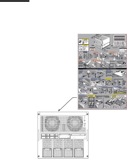
Alert Labels
The followings are labels attached to this product:
■ Never peel off the labels.
FF2 (Front View)
xxviii SPARC Enterprise M4000/M5000 Servers Service Manual • August 2009
Loading...